Device Fabrication Example Group 2 pn junction Diode

Device Fabrication Example Group: - 2

pn junction Diode Fabrication Start: � The starting point is a flat, damage-free , singlecrystal, Si wafer. � Common dopants are boron for P-type layers and phosphorus, antimony and Arsenic for N-type layers. � Assume the wafer is p-type, having been uniformly doped with boron during the formation of the crystal.

1. Oxidation: � The process of oxidation consists of growing a thin film of silicon dioxide on the surface of the silicon wafer. � It will serve as a diffusion barrier. �The oxide thickness must be comfortably greater than the projected masking thickness.

2. Lithography#1: � This process performed to open “diffusion” holes in the oxide that will eventually become the positions of the pn junction diodes.

3. Phosphorus Diffusion � After a proper clean-up the wafer is nest inserted into a phosphorus pre-deposition Furnace. � The formation of n+ -p junctions is surface regions not protected by the oxide. (The + in n+ is indicate a very high doping.
 � Evaporation of Al yields a thin metal film over the")
4. Metallization(sputter Al) � Evaporation of Al yields a thin metal film over the entire surface of the wafer due to connect the device to the ‘’outside world’’

5. Lithography #2: � It is performed to remove excess metal external to the area of the diffused junction.

� To produce commercial diodes, a diamond-edged saw would be used to cut the wafer into pieces containing a single device.
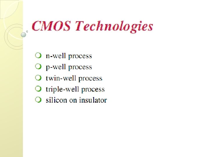

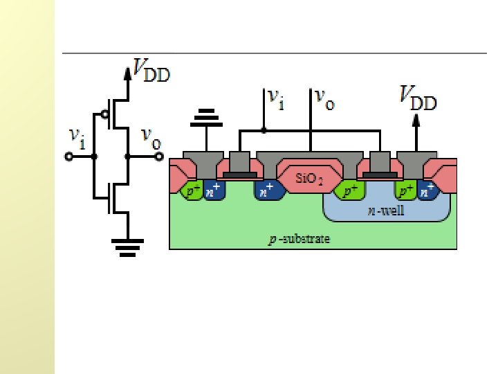
n-well process Fabrication Steps �Typically use p-type substrate for n. MOS transistors �Requires n-well for body of p. MOS transistors

Oxidation � Blank wafer covered with a layer of Si. O 2 using oxidation

Photoresist �Spin on photoresist ◦ Photoresist is a light-sensitive organic polymer ◦ Softens where exposed to light

Lithography �Expose mask photoresist through n-well
")
Etch �Etch the uncovered oxide using HF (Hydroflouric acid)

Strip Photoresist �Etch the remaining photoresist using a mixture of acids

n-well �n-well is formed using either diffusion or ion implantation

Strip Oxide �Strip off remaining oxide using HF. Subsequent steps use the same photolithography process
 of silicon")
Polysilicon � Deposit thin layer of oxide. � Chemical Vapor Deposition (CVD) of silicon layer ◦ Forms many small crystals called polysilicon ◦ Heavily doped to be good conductor

Polysilicon Patterning �Use same lithography process to pattern polysilicon

Self-Aligned Process �Cover with oxide to define n diffusion regions

N-diffusion �Pattern oxide using n+ active mask to define n diffusion regions

N-diffusion cont. �Diffusion or ion implantation used to create n diffusion regions

N-diffusion cont. �Strip off the oxide to complete patterning step

P-Diffusion � Similar set of steps form p+ diffusion regions for p. MOS source and drain and substrate contact

Contacts � Cover chip with thick field oxide � Etch oxide where contact cuts are needed

Metallization � Sputter on aluminum over whole wafer � Remove excess metal leaving wires

Detailed Mask Views �Six ◦ ◦ ◦ masks n-well Polysilicon n+ diffusion p+ diffusion Contact Metal Fabrication and Layout Slid e 28

3 D Structure

Thanks
- Slides: 31