Development of Port Fuel Injection System P M


- Slides: 14

Development of Port Fuel Injection System P M V Subbarao Professor Mechanical Engineering Department Hardware to Satisfy the Needs of Otto Cycle. …. . .

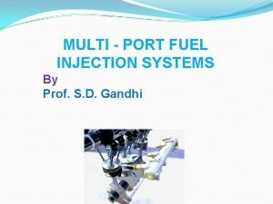
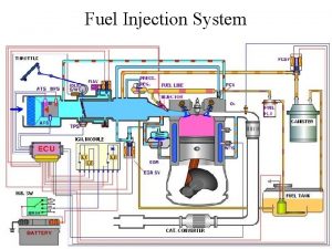
Port Fuel Injection System

The Process of (Electronic) Injection Method • The first step is to know the time of injection. • The second step is to know the location of fuel injection. • The third step is to control the quality of fuel spray in the port. • Are they independent or inter related? • The fuel economy and emissions are strongly influenced by the structure and spray pattern.

Role of Angles in Fuel Distribution in Port After injection, the droplets flow takes place in the intake port Orientation Angle of Injector Orientation Angle of Valve Orientation Angle of intake port Spray Angle

Air –Fuel Interactions in the Manifold • As the droplet group moves in the air stream, it decelerates or accelerates depending on operating conditions. • At the same time, the droplets vaporization is initiated. • As the droplets move to the end of the pipe, some of the unvaporized droplets are assumed to impinge on the intake port wall bend to form a droplet deposition film. Because of the heat transfer from the wall and from the air stream, the liquid film continuously vaporizes.

Two Way Air –Fuel Interactions in the Manifold • The processes described above influence the state of the gas, i. e. , the gas stream may be retarded, speeded up, cooled and enriched with fuel-vapor components. • The changes in the gas-phase properties in turn influence the dynamics and vaporization of droplets, which are subsequently injected. A comprehensive computer program is essential to analyze the dynamic of fuel evaporation and carry-over of un-evaporated fuel by air.

Instantaneous Rate of Fuel Evaporation in Port • Instantaneous rate of fuel evaporation in a port is the sum of evaporation rate of fuel droplets and evaporation rate of fuel films

Physics of Droplet Evaporation Basic Mechanism : Convective Mass Transfer

Evaporation rate of droplet • The evaporation rate of a droplet is a resultant of two independent evaporation effects namely; • The evaporation of a stationary droplet existing in a quiescent environment and • the evaporation due to a relative velocity exists between the droplet and its gaseous environment.

Evaporation rate of Stationary Droplet : Diffusion Mass Transfer B is a Spalding mass transfer number

Evaporation due to Relative Velocity : Convection Mass Transfer This convection factor is a function of the droplet Reynolds number (Red) and the Schmidt number (Sc)

Film Evaporation • The film vaporization rate is determined by where h. D is the mass transfer coefficient, and BM the mass transfer number, as described above. For the wall film, the energy equation is described by: where h and kf are the heat transfer coefficient and the liquid fuel thermal conductivity. The terms in right hand of equation are the heat transfer rate from gas to fuel film on the gas side, the heat transfer rate used for vaporization and the heat transfer from wall to the film respectively.

What is the Representative Droplet Size?

Physics of Spray Formation • The combination of these two geometric parameters was denoted as spray “targeting” among fuel systems engineers. • It soon emerged as a prime consideration in selecting an injector design for minimizing unburned hydrocarbon emissions. • Made the engineers to understand physics of Spray Formation. • Spray formation is explained as Breakup Mechanism, described as: • Stretching of fuel ligament into sheets or streams. • Appearance of ripples and protuberances. • Formation of small ligaments or holes in sheets. • Collapse of ligaments or holes in sheets. • Further breakup due to vibration of droplets. • Agglomeration or shedding from large drops.
 D mpfi is injection system port valve crackcase manifold
 L m p f i system uses
 Synerject fuel injection
 Synerjet m3c
 Spray quality
 Which of the following are features of 8255a
 In bsr mode
 Tutorial
 Caterpillar common rail fuel system
 Fuel monitoring system for vehicles
 Gas turbine engine fuel system
 3 step fuel system cleaner
 Htars fuel system
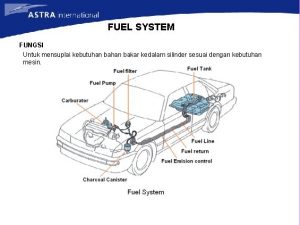
 Fungsi fuel system
 Diesel engine fuel system diagram
