
Development of EUC End User Computing System for

- Slides: 17
Development of EUC (End User Computing) System for the Design of HVAC (Heating, Ventilation and Air Conditioning) O. Yoshida, M. Andou Tokyo Gas Co. , Ltd.
Contents • • • Introduction Feature of the EUC system Wide variety of DB (data-base) Original user-subroutines Verification of DB Conclusions
Introduction • CFD methods have become a promising tool to optimise design parameters of HVAC by predicting thermal environment in buildings. • While many advantage are expected, CFD codes still require lots of expertise and time for designers to model and predict indoor environment. • Wider application of CFD has been expected, in particular, to the field of EUC that designers and even sales engineers can easily take advantage of. An EUC system for the optimal design of HVAC has been developed.
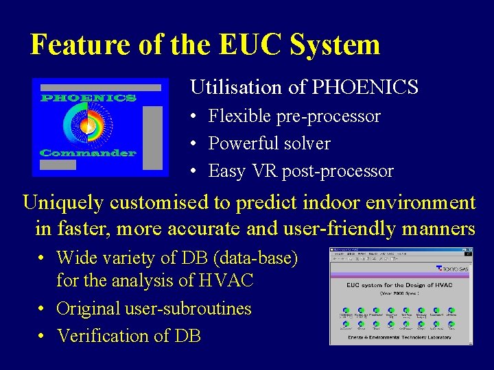
Feature of the EUC System Utilisation of PHOENICS • Flexible pre-processor • Powerful solver • Easy VR post-processor Uniquely customised to predict indoor environment in faster, more accurate and user-friendly manners • Wide variety of DB (data-base) for the analysis of HVAC • Original user-subroutines • Verification of DB
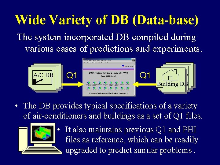
Wide Variety of DB (Data-base) The system incorporated DB compiled during various cases of predictions and experiments. A/C DB Q 1 A/C type Building DB • The DB provides typical specifications of a variety of air-conditioners and buildings as a set of Q 1 files. • It also maintains previous Q 1 and PHI files as reference, which can be readily upgraded to predict similar problems.
Original User-subroutines • Along with the DB, series of practical usersubroutines have been developed using GROUND. • These user-subroutines are applicable to predict ideal performance and operating conditions of airconditioning units under desired optimal thermal environment. • Optimisation of input conditions such as efflux temperature is conducted to obtain desired thermal environment in a room.
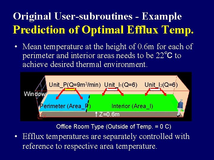
Original User-subroutines - Example Prediction of Optimal Efflux Temp. • Mean temperature at the height of 0. 6 m for each of perimeter and interior areas needs to be 22℃ to achieve desired thermal environment. Unit_P(Q=9 m 3/min) Unit_I 1(Q=6) Unit_I 2(Q=6) Window Perimeter (Area_P) Interior (Area_I) Z=0. 6 m Office Room Type (Outside of Temp. = 0 C) • Efflux temperatures are separately controlled with reference to respective area temperature.
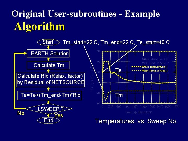
Original User-subroutines - Example Algorithm Start Tm_start=22 C, Tm_end=22 C, Te_start=40 C EARTH Solution Calculate Tm Calculate Rlx (Relax. factor) by Residual of NETSOURCE Te=Te+(Tm_end-Tm)*Rlx No LSWEEP ? Yes End Te Tm Temperatures. vs. Sweep No.
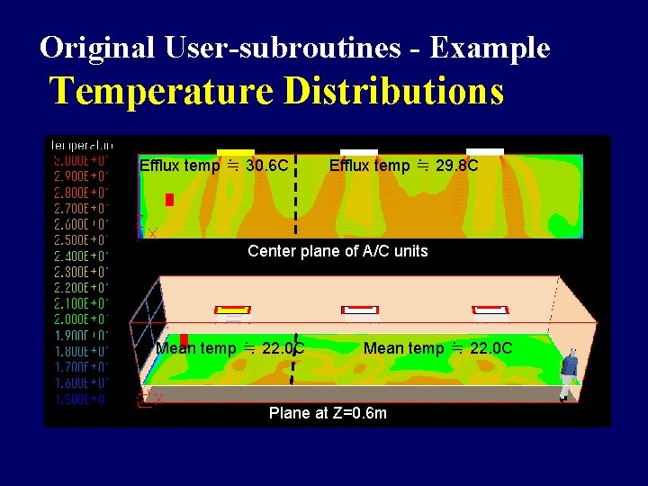
Original User-subroutines - Example Temperature Distributions Efflux temp ≒ 30. 6 C Efflux temp ≒ 29. 8 C Center plane of A/C units Mean temp ≒ 22. 0 C Plane at Z=0. 6 m
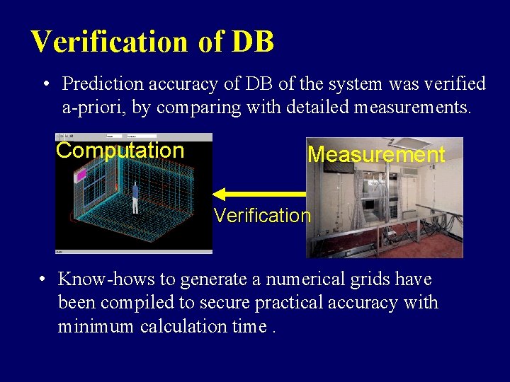
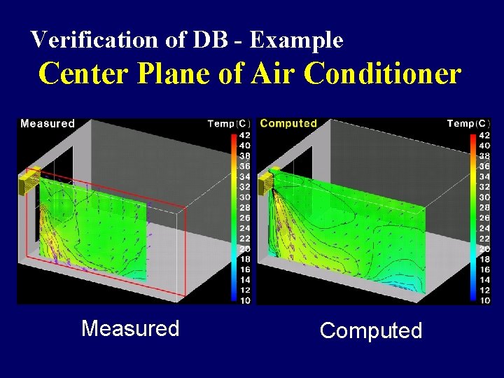
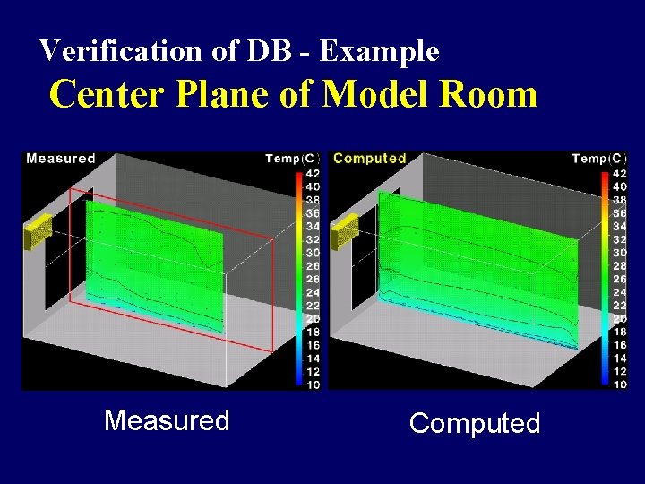
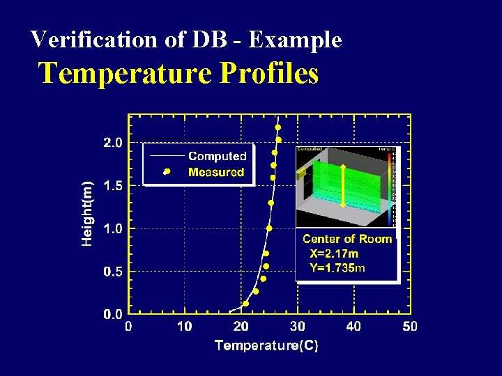
Verification of DB • Prediction accuracy of DB of the system was verified a-priori, by comparing with detailed measurements. Computation Measurement Verification • Know-hows to generate a numerical grids have been compiled to secure practical accuracy with minimum calculation time.
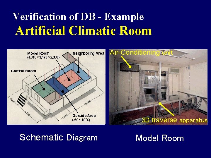
Verification of DB - Example Artificial Climatic Room Air-Conditioning unit 3 D traverse apparatus Schematic Diagram Model Room
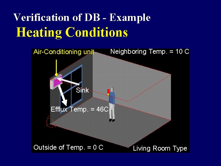
Verification of DB - Example Heating Conditions Air-Conditioning unit Neighboring Temp. = 10 C Sink Efflux Temp. = 46 C Outside of Temp. = 0 C Living Room Type
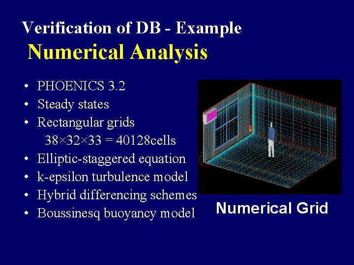
Verification of DB - Example Numerical Analysis • PHOENICS 3. 2 • Steady states • Rectangular grids 38× 32× 33 = 40128 cells • Elliptic-staggered equation • k-epsilon turbulence model • Hybrid differencing schemes • Boussinesq buoyancy model Numerical Grid
Verification of DB - Example Center Plane of Air Conditioner Measured Computed
Verification of DB - Example Center Plane of Model Room Measured Computed
Verification of DB - Example Temperature Profiles ●
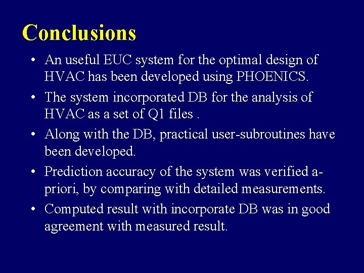
Conclusions • An useful EUC system for the optimal design of HVAC has been developed using PHOENICS. • The system incorporated DB for the analysis of HVAC as a set of Q 1 files. • Along with the DB, practical user-subroutines have been developed. • Prediction accuracy of the system was verified apriori, by comparing with detailed measurements. • Computed result with incorporate DB was in good agreement with measured result.