Development of a lownoise analog frontend ASIC for

 • Introduction • Circuit")


")


 + + LYSO 2")
 @0 p. F ⇒achieved")


 Walk Fluctuation")
 Experimental 870 ps")


")
 Format Frame 1 101 Hit order Frame Number 1 TAC")
- Slides: 32
Development of a low-noise analog front-end ASIC for APD-PET detectors 2008. 9. 4 PSD 8@University of Glasgow 256 ch APD-array 8 ch Analog ASIC Makoto Koizumi (Tokyo Tech) J. Kataoka, S. Tanaka, H. Ishibashi, N. Kawai (Tokyo Tech) H. Ikeda (JAXA) Y. Ishikawa, N. Kawabata, Y. Matsunaga, K. Shimizu (Hamamatsu Photonics)
Outline Development and evaluation of 8 -channel ASIC (ver. 1) • Introduction • Circuit Architecture • Performance Ver. 1 8 ch Future prospects • 32 -channel ASIC (ver. 2) • Mobile PET unit Conclusion Ver. 2 32 ch 2
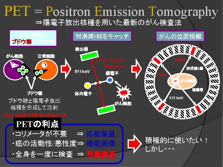
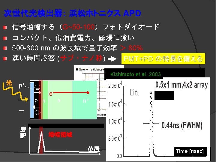
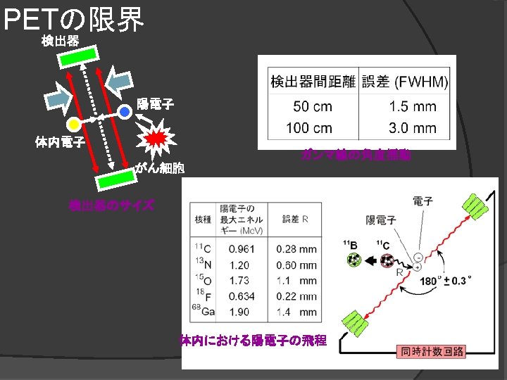
3 Introduction We are now developing high spatial resolution, low-cost and multipurpose next generation PET detectors by using APD-arrays. (1) sensor head (pixel scinti. ) ~80 mm (3)Analog front-end electronics with ASIC 30 mm 30 m m (2) APD-array ü Flexible, low-cost mobile PET w/ sub-mm resol. ü Application to MRI/PET and TOF-PET. Woody et al. (2003)
Introduction Requirements for APD-PET front-end electronics ・Simultaneous processing of multiple channels ( > 8 -channel) ・CSA gain optimized to APD (~ 50 times) ・Fast Shaping time optimized to decay time of LYSO (~ 40 ns) ・Time-of-Flight capability (< 1 ns) ・High energy resolution ・Low-noise and low-power consumption We have developed an analog front-end ASIC which meets these specifications in cooperation with JAXA. 4
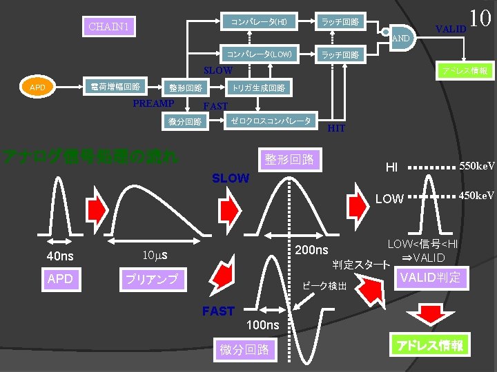
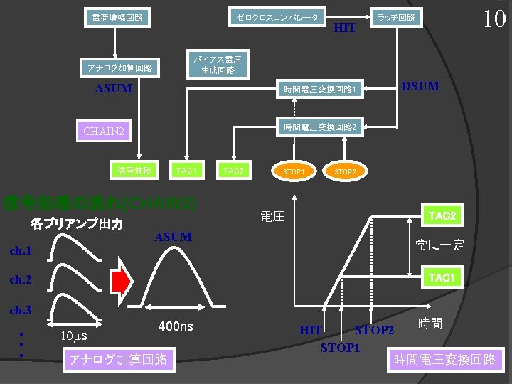
Circuit Architecture ch 7 ・ DATA VALID ・ ・ APDarray Position Information (LVDS out) Parallel to Serial PREAMP ch 0 CSA SLOW Shaper (t~ 100 ns) Energy Discriminator FAST Differentiator (t~ 50 ns) Zero-crossing Discriminator CHAIN 1 CHAIN 2 Analog Sum (t~ 200 ns) Energy Information (Analog out) BIAS TAC 1 TAC 2 Timing Information (Analog out) 5
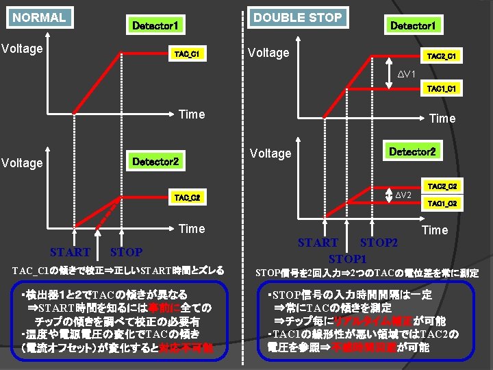
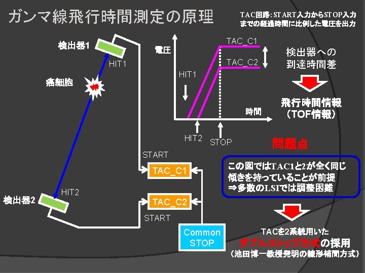
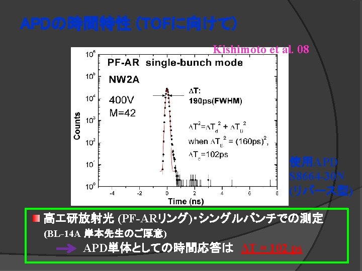
Zero-crossing method It is very important to obtain true hit timing information with various events for Time-of-Flight based PET Apply the most simple zero-crossing method Shaper output SLOW Zero-crossing method 1. SLOW reaches to signal peak 2. Its differential signal FAST crosses zero point 3. Zero-crossing comparator turns on to start TACs 200 ns FAST 100 ns Differentiator output Peak detection Time walk within 600 ps was expected with 511 ke. V± 13% 6
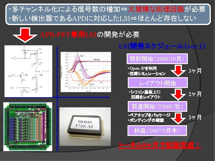
2007/5/29 : Completed 80 -pin Ceramic Package 3 mm 14 mm 20 mm 3 mm ・Process:TSMC 0. 35μm CMOS ・Chip size: 3 mm× 3 mm ・Package: 80 pin Ceramic QFP ・Number of channels: 8 ch ・Power consumption: 55 m. W (6. 9 m. W/ch) Testing board 7
8 Experimental results : Waveforms Simulation Experimental FAST PREAMP SLOW ASUM ・Experimental waveforms were consistent with simulation results. ・Gain dispersion and offset voltages were within adjustable ranges.
Experimental results : Noise performance experimental 2 mm□ 13. 6 p. F 1 mm□ 3. 4 p. F simulation Excess exists ENC : below 1000 e- for 2 mm□ S/N : 100 times ensured ・Equivalent Noise Charge (ENC): 600 e- + 28 e- / p. F (RMS) ・Certain excess exists between experimental and simulation results. ⇒It might be the floating capacitance of a relatively large package. 9
Experimental results : Energy resolution 370 V operation (22 Na) + + LYSO 2 mm□ APD 2 mm□ TIPPET 08 No. 30_ch 2 ・Resolution: 9. 7 % (FWHM) @ 511 ke. V ⇒Sufficient performance for APD-PET 10
Experimental results : Time resolution Time Resolution: 970 psec (RMS) @0 p. F ⇒achieved by simple zero-cross method. 11
12 2 nd version ASIC “TIPPET 32” Main differences 13 mm LTCC QFP Low Temperature Co-fired Ceramics package 3 mm Number of channels : 8 ch → 32 ch Order of the shaper : 2 nd → 3 rd Time resolution : 970 ps → 570 ps Package : QFP → LTCC Polo-Zero-Cancellation (PZC) Priority chain encoder 8 mm
Mobile APD-PET unit LYSO-array All front-end processing are coverd ⇒It can be connected flexibly !! APD-array Front-end Card (FEC) × 4 8 cm Control Card (CC) × 1 3 cm 13
Summary 14 Our goal is to realize a high-resolution, low-cost and multipurpose next-generation PET detectors. TIPPET 08 (1 st version) ・We manufactured 8 -channel analog ASIC optimized to APD ・Good energy resolution of 9. 7%(FWHM) @ 511 ke. V with APD ・Good time resolution of 970 ps(RMS) @0 p. F ・Low-noise of 600 e- + 28 e- / p. F with low-power of 6. 9 m. W/ch. TIPPET 32 (2 nd version) ・We are now developing and evaluating 32 -channel 2 nd version ASIC ・Good time resolution of 570 ps(RMS) @0 p. F ・Low-noise of 560 e- + 30 e- / p. F with low-power of 6. 0 m. W/ch. We plan to evaluate spatial resolution with one-pair unit
Thank you !
BACKUP
2 nd version ASIC “TIPPET 32” NOISE FAST σj Jitter Vth FAST(+10%) Walk Fluctuation of zero-cross point (511 ke. V± 10%) Vth σw FAST(-10%) 8 ch (ver. 1) → multiplied to 32 ch (ver. 2) Largely improved time resolution • Dt jitter ~ 970 ps → ~ 580 ps (ver. 2) • Dt walk ~ 600 ps → ~ 60 ps (ver. 2) Low Temperature Co-fired Ceramics (LTCC) Package is specially used. LTCC package(KOA)
Time walk Simulation 600 ps (511 ke. V ± 12. 5%) Experimental 870 ps (511 ke. V ± 12. 5%)
APD-PET用LSIver. 2:PETシステム全体図 Extended Mobile PET Unit Front End Card× 4 APDarray 256 c h LSI_C 0 32 ch ADC AD 9287 LSI_C 1 32 ch DAC AD 5360 ・FEC 1枚あたり2 chipを搭載し、64 ch分を担当 ・CCのFPGAでFEC 4枚分、APD 256 ch分を一括処理し、 同時計数回路への橋渡しを行う Control Card FPGA Cyclone Ⅲ EP 3 C 25 Coincidence Circuit
APD-PET用LSIver. 2:PETモードでの信号の流れ FPGAの役割 FADC 8 bit 256 c h APDarray TAC 1 FADC 8 bit 時間情報 TAC 2 8 bit TAC1 8 bit TAC 2 アドレス情報 LSI_C 0 32 ch SDAV DSUMOUT 時間関係 アドレス関係 STOP 1 STOP 2 READ RCK RESET FPGA LSI_C 1 LSI_C 2 … LSI_C 7 Minor Clock Major Clock ・ 1ユニット、8チップの統括 ・時間情報とアドレス情報を浜松 式のフォーマットに整形 ・チップIDの割り振り ・LSIのch毎の校正(JTAG使用) ・TACのSTOP信号、RESET信号 の生成 ・ADC及びDACのオペレーション アドレス情報 Chip. ID 8 bit+ HITadd. 8 bit 時間情報 TAC1 8 bit+ TAC 2 8 bit Coincidenc e Circuit
Coincidence Detector Input Format Frame 1 Valid Flag Minor Clock Counts(4 or 5 bit) HIT Address (8 bit) TAC 1_out (8 bit) Frame No. Frame 2 Valid Flag Minor Clock Counts(4 or 5 bit) HIT Address (8 bit) TAC 2_out (8 bit) Frame No.
Coincidence Detector Output (IJ-data) Format Frame 1 101 Hit order Frame Number 1 TAC 1 -out Detector-2 X TAC 2 -out Detector-1 TAC 2 -out Detector-2 X Y Detector-1 X Y Detector-2 Frame 2 110 Hit order Frame Number 2 Y Detector-1 X Y Detector-2