Development of a coherent Doppler lidar for precision


- Slides: 23

Development of a coherent Doppler lidar for precision maneuvering and landing of space vehicles Farzin Amzajerdian, Glenn D. Hines, Diego F. Pierrottet, Bruce W. Barnes, Aram Gragossian, Mitchell J. Davis, Tak-kwong Ng, Alexander D. Scammell, Adam Ben Shabat, Larry B. Petway, and John M. Carson NASA Langley Research Center 19 th Coherent Laser Radar Conference June 18 -21, 2018

Frequency Modulated, Continuous Wave (FMCW) Waveform 3 segments waveform minimizes false alarms due to zero-crossing and signal ambiguity 2

Navigation Doppler Lidar (NDL) Ø NDL Measures velocity and range along three different laser beams Ø Simultaneous line-of-sight measurements are used to estimate: § Velocity Vector (V) § Altitude relative to local ground (No IMU data required) 3

NDL Replaces Radars on Space Vehicles Ø Past landing missions used radars for vehicle position and velocity data in absence of GPS Ø NDL offers an order of magnitude higher precision and much higher data quality (low false alarms) while reducing required size, mass, and power Ø NDL enables “precision navigation” to the designated landing location Ø NDL enables “well-controlled” descent, landing, and ascent maneuvers to within a few cm/sec • Reduced touchdown impact loads lower lander mass • Optimized fuel consumption lower mass and risk 4

NDL development from breadboard to fully-autonomous prototype rocket-powered free-flyer vehicles 2008 Brea dboa rd w ithou 2010 proc ~200 kg essi t real-tim ng e GEN 1: ~ 60 kg 2012 Fully GEN 2: 28 kg -Aut 2014 onom ous GEN 2. 1: 17 kg Prot otyp e 2017 GEN 3: 10 kg 5

GEN 3 NDL § Fully-autonomous operation § Integrated real-time processors § Robust operation onboard different terrestrial vehicles Chassis 11”x 9”x 8” Optical Head 2” lenses 6

NDL Characterization Operational Range Measurements at Langley AFB Runway Gantry Tests NDL Setup NDL Optical Head Calibrated Target on back of a truck driven on the runway 7

NDL Operational Range Measurement Mean Intensity

Maximum Operational Range Predications Relative Signal Intensity Ø Maximum operational ranges in Mars and Moon extrapolated from measured data • Mars 5. 7 km • Moon 7. 5 km Lidar Equation Target reflectivity = 0. 5 Humidity = 70% Visibility = 17 km Moderate Turbulence Cn 2 = 3 e-14 Mean of measured intensity data Mars Perf Projection with nominal atmospheric and Moon Perf surface albedo Projection Measurement threshold Range (m)

GEN 3 NDL Performance Maximum LOS Rangea Maximum LOS Velocity Errorb LOS Range Errorb Data Rate Electronic Chassis Dimensions Optical Head Electronic Chassis. C Mass Optical Head Power (28 VDC) C > 4500 m 200 m/sec 0. 2 cm/sec 25 cm 20 Hz 28 x 22 x 20 cm 34 x 33 x 21 cm 8. 7 kg 5 kg 80 W a. Dependent on atmosphere and surface albedo b. Errors dominated by the vehicle’s vibration and angular motions (1. 7 cm/sec and 2. 2 m in flight tests) c. Heatsink and fans module for terrestrial operation adds 1. 5 kg and 10 W

Key NDL Features Ø Ø Ø Ø Stable, Narrow Linewidth, Low Noise Laser Stable and Low Noise Fiber Amp In-house built C&DH board 20 layers and thousands traces Highly Linear Modulation Waveform Low Noise, Flat Response, and Well-Balanced Receiver High Resolution FFT Processor Robust Signal Processing Algorithm Compact Chassis • Efficient Thermal Design • Mechanically Robust 3 -channel Dual-Balanced Receiver 11

Spaceflight Engineering Test Unit (ETU) Ø Ø Ø Use “space-qualified” or “space-qualifiable” parts Conduct radiation and thermal/vacuum tests at component/subsystem level Efficient heat conduction to host vehicle Robust structure EMI resistance NDL-3 ETU

Future Work Ø Complete and test Spaceflight Engineering Test Unit (ETU) by mid 2019 • Flight tests onboard a high speed aircraft and a rocket-powered vehicle in summer 2019 Ø Continue study and field testing for terrestrial applications • Autonomous ground aerial vehicles • Helicopter landing in degraded visual environments (DVEs) • Other proprietary applications Ø Continue technology advancement • Miniaturization • Expand NDL capabilities for other space and terrestrial applications 13

Backup 14

Principle of Navigation Doppler Lidar Frequency Modulated, Continuous Wave (FMCW) Technique Frequency Bandwidth Period Time delay is a measure of target range Detector Output (beat frequency) Target velocity causes up and down beat frequencies to separate Time

NDL Real-Time Processor & System Controller NDL Modulation Waveform

Comparison of NDL and MSL Radar Navigational Doppler Lidar Chassis MSL Doppler Radar Optical Head 24 cm m c 17 130 cm x 50 cm x 40 cm 35 cm 18 cm dia x 20 cm H MSL Radar NDL Mass (kg) 26 13 Power (W) 120 80 6 antennas each 22 cm diameter, 4 cm thick Optical Head Ø 30 X higher velocity and altitude precision Ø 3 orders of magnitude tighter beams Ø 40% reduction in power, 50% in mass, and 60% in size 17

Morpheus Flight Demonstrations § 3 -D Flash Lidar mapped the terrain for real-time hazard detection and avoidance Navigation Doppler Lidar Flash Lidar § NDL provided data for precision navigation and soft landing at the selected site § 3 open loop flights (April 2014) § 3 closed loop flights (two in May 2014 and one in December 2014) Doppler Lidar Head Approx. 450 m slant range 30 degree glideslope 100 m x 100 m hazard field Shuttle Landing Facility, NASA-KSC Laser Altimeter

Morpheus Flight Test Data Velocity Magnitude 350 300 Range (m) velocity (m/s) 16 12 8 Altitude 250 200 150 100 4 50 0 10 20 30 40 50 60 70 80 90 100 110 time (s) 0 10 20 30 40 50 60 70 80 90 100 110 time (s) Takeoff Landing

Comparison with IMU/GPS measurements NDL LOS velocity compared to vehicle NAV using IMU, GPS, and a laser altimeter 0. 2 LOS Residuals, m/sec 0. 15 0. 1 0. 05 0 -0. 05 -0. 15 -0. 2 0 10 20 30 40 50 60 70 80 80 100 110 Time, second Ø NDL data in excellent agreement with IMU/GPS/Altimeter data Ø NDL provides more accurate and precise vehicle state vector (position and velocity vector) than GPS Ø NDL surface-relative measurements are highly precise with negligible bias 20

Ongoing Free-Flyer Test Campaign COBALT Payload = NDL + Terrain Relative Navigation (TRN) sensor + Navigation Filter Altitude 500 m COBALT NDL 465 m Start 25 m/s descent Di v er 100 m t 10 m 20 m 300 m 21

Non-Space Applications of NDL Ø NDL can enable precision navigation in GPS-deprived environments Ø NDL can assist landing in degraded visual environments (DVEs) such as brownout condition Ø NDL can provide 3 -D range and velocity map of surroundings

Spaceflight Engineering Test Unit (ETU) Development Approach Ø Electronic parts • Use “space-grade” or “space-grade EM” parts • Few parts have no space-grade equivalents ‒ Change design or qualify COTS parts (i. e. , conduct radiation and thermal/vacuum tests) Ø Photonic and fiber optic parts • Leverage spaceflight qualification heritage when possible • Custom-design for space environments (vacuum, 0 g, radiation, thermal, vibration) • Conduct radiation and thermal/vacuum tests as necessary Ø Perform Th/Vac and Vibration tests on major subsystems Ø Subject assembled ETU Chassis to environmental tests 23
 What is non precision instruments
 Precision vs semi precision attachment
 Bcd gösterimi
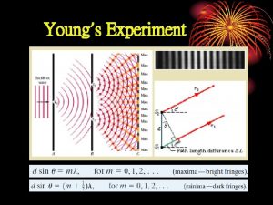
 Path length difference
 Vgin lidar
 Radar lidar
 Coherent text
 Raspberry pi lidar
 Nominal substitution examples
 I was not aware
 Lidar schematic
 Coherent and cohesion meaning
 Blinder xtreme 7 series
 Coherent interface
 Coherent detection in optical communication
 Coherent vs incoherent scattering
 Coherent and cohesion meaning
 Lidar wind profiler
 Pessoas que se sentem superiores
 Puget sound lidar consortium
 Coherent scattering
 Open capi
 Difference between pulse doppler radar and mti radar
 Lidar system component


