Determination of heights essential terms 1 Equipotential surface


- Slides: 29

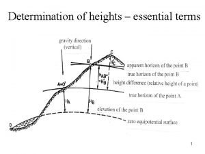
Determination of heights – essential terms 1

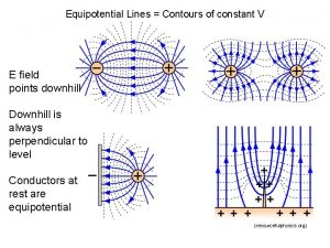
Equipotential surface = a surface with the invariable gravity potential (perpendicular to the force of gravity in each point). Equipotential surfaces are not parallel mutually and they converge in the direction to the Pole. For our purposes (i. e. for purposes of land surveying) the Earth is supposed to be a homogenous sphere. Then the zero equipotential surface is a spherical surface which comes through the zero height point and equipotential surfaces are concentric spherical surfaces. 2

Absolute height of a point = height of a point above a chosen zero surface. The zero equipotential surface is the mean sea level absolute height of a point = elevation (sea level height). Relative height of a point = height of a point above an arbitrarily chosen equipotential surface, relative height of a point is actually a height difference. 3

True horizon of a point = equipotential surface which comes through the point. Apparent horizon of a point = horizontal tangent plane in the point. The Earth is supposed to be a plane and then true horizons are supposed to be apparent horizons (it means that the Earth’s curvature can be negleted) for surveying within the distance about 300 m – see p. 5, 6. 4

Influence of the Earth’s curvature on heights 5

Influence of the Earth’s curvature on heights = d. tg /2 d. /2 /2 = d / 2 r = d 2 / 2 r d [m] Δ [mm] 50 0 350 10 1000 83 6

Height differences (of true horizons) are measured h. AB = HB – HA 7

Vertical datum in the Czech Republic 1. Baltic Vertical Datum – after Adjustment (Bpv) the zero height point = the zero point of the water gauge in Kronshtadt (Russia) 2. Adriatic datum – effective until 2000 (in Prague) the zero height point – in Trieste (Italy) The height difference between Bpv and Adriatic datum is about 0, 40 m (heights are higher in Adriatic datum). 8

Methods of a height difference determination 1. direct levelling 2. barometric levelling 3. hydrostatic levelling 4. trigonometric method 5. Global Navigation Satellite Systems (GNSS) 9

Direct levelling from the center between the rods h. AB = HB – HA = b – f Section of levelling = backward levelling rod + levelling instrument + forward levelling rod. The Earth’s curvature and an inclination of the line of sight are eliminated using this method. If there are several sections of levelling (levelling line), then h. AB = b – f 10

Types of direct levelling according to precision 1. 2. 3. 4. special-precision levelling hight-precision levelling precise levelling technical levelling (TL) 11

Accuracy criterion of TL – maximum difference between height differences determined twice M = 40 r r … length of a levelling line (if the levelling line is measured twice) or half-length of a levelling line (if the levelling line is measured once) in km M … in mm 12

Levelling instruments Principle – a horizontal plane is set out by a levelling instrument. 1. optical levelling instruments 2. electronical levelling instruments 3. laser levelling instruments 13

1. Optical levelling instruments 1. levelling instruments The line of sight is levelled to the horizontal position by a levelling bubble. 2. self-compensating levelling instruments The line of sight is levelled to the horizontal position automatically by a compensator (pendulum). The circular level of the instrument has to be levelled in order that the compensator works. 14

Levelling instruments - optical

2. Electronical levelling instruments • levelling rods with a barcode are used • the barcode is read by a CCD camera automatically, the reading is recorded and calculation is performed automatically • errors caused by the observer are reduced 16

Levelling instruments - electronical

3. Laser levelling instruments • line of sight = visible laser beam (most often He-Ne, semiconductor) • a visible plane of sight can be realised • a sensor is placed on the rod for determination of the beam’s centre (a divergence of the laser beam is about 30 mm for 200 m) • accuracy of instruments is about 2 mm/100 m 18

Levelling instruments - laser

Levelling instruments - equipment Levelling rods, footplates

Types of direct levelling with respect to procedure 1. traverse levelling – sections of levelling with backsights, foresights and intermediate sights (exceptionally) – see practical classes 2. longitudinal profiles and cross section levelling – 3. surface levelling 21

2. Longitudinal profiles and cross section levelling • often used for design and building of linear constructions (roads, railways), for a regulation of watercourse, . . . longitudinal profile = vertical section of a terrain which comes through the axis of the construction cross section = vertical section of a terrain which is perpendicular to the axis of the construction 22

• technical levelling with intermediate sights is used for the heights determination of longitudinal and cross profiles points • characteristic points (the beginning and the end of the arc) and other points in periodic space (e. g. 20 m) are measured • requirement = accuracy should be in cm the fundamental of the levelling from the centre between the rods can be contravened 23

Measurement of a longitudinal profile 24

• longitudinal profile is displayed on a graph paper (cross-section paper) • heights are ususally displayed using larger scale (e. g. 1: 100) than scale for distances (e. g. 1: 1000) to stress altitudinal component • vertical alignment of the linear construction axis is designed to the longitudinal profile and then earthwork is calculated • vertical alignment is usually designed to have fills the same as cuts approximately (equal cubages = minimal earthwork) 25

26

Cross section • number of cross sections depends on the fact if the relief is broken or plane. A choice of places for cross profiles supports a calculation of earthwork cubages as precisely as necessary. • length of a cross profile depends on earthwork, it ranges usually from 20 m to 200 m • perpendicular to the building axis is set out in the point of longitudinal profile and outer points and points which lie on breaks of the terrain are measured • it is possible to measure cross section points simultaneously with longitudinal profile points 27

Choice of cross section points 28

The cross section is displayed on a graph paper (cross-section paper), the scale is the same both for heights and distances (e. g. 1: 100). 29
 Equipotential surface
 What do you understand by equipotential surface
 Potential and capacitance
 Equipotential surface
 Shape of equipotential surface in uniform electric field
 Visible surface determination
 Visible surface determination
 Can two equipotential surfaces intersect
 Flow rate
 Equal potential grounding
 Gpe= mgh
 Define electric potential and potential difference.
 Equipotential lines
 Electric potential isolines
 Characteristics of lipids
 Like terms and unlike terms in polynomials
 Combining like terms definition
 Lateral surface area for a triangular prism
 Spin coat
 Surface area of a cone
 How to calculate sst in regression
 Target market structure
 How to use sodium benzoate in fruit juice
 Aspirin back titration
 Price discovery and price determination
 Maltose standard curve
 Mercuric nitrate method for chloride determination
 Grit vs determination
 Hemophilia punnet square
 Shipping point determination
