Detention Basics 1 Detention Basics 2 Objectives Students

Detention Basics 1

Detention Basics 2

Objectives Students should have the ability to: Name the advantages of a detention basin n Develop an inflow hydrograph n Determine a stage-storage curve n Determine an outflow curve for single or multi-staged outlets n 3
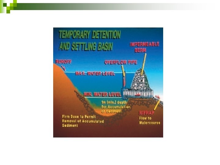

Detention Basin-Purposes Store water temporarily during a storm and release the stored water slowly (attenuate the flow) n Store first-flush n Allow and/or Design for infiltration n ¨ If all water is infiltrated then (retention basin) 5

Detention Basins On-Site n Regional n Discussion 6
 n Storage n Outflow (single/multiple stage) n ¨")
Detention Basins Inflow (ditch or pipe) n Storage n Outflow (single/multiple stage) n ¨ Orifice ¨ Weir n Emergency spillway 7

Routing Method used to model the outflow hydrograph n Based on continuity equation n ¨ Water in varies ¨ Water out varies ¨ Storage 8

Information Needed to Route Inflow hydrograph n Table or graph of storage volume to water elevation in the proposed detention basin n Table or graph of outflow to water elevation (discharge rating) n 9
 Ch 5 of TR-55 (NRCS method) n Modified rational method")
Inflow hydrograph (3 methods) Ch 5 of TR-55 (NRCS method) n Modified rational method (see book 11. 2) n ¨ Simple symmetrical triangle (2*tc) ¨ Asymmetrical triangle (total base = 2. 67 tc) 10
 Peak flow is higher after development Peak flow occurs earlier")
TR-55 Hydrograph (NRCS Method) Peak flow is higher after development Peak flow occurs earlier after development

Rational Method: Simple Symmetrical Triangle

Rational Method: Time base of 2. 67 tc Area under hydrograph?
 ¨ Average End-Area (pipes)")
Computing Storage Volumes n Two Methods ¨ Elevation-Area (detention basins) ¨ Average End-Area (pipes) 14
 ¨ Contour lines are determined around basin")
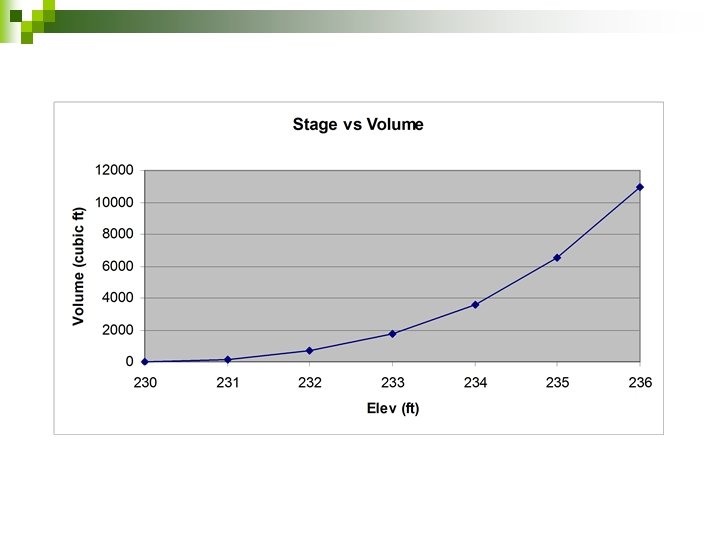
Computing Storage Volumes n Elevation-Area (detention basins) ¨ Contour lines are determined around basin ¨ Determine area of each contour ¨ Volume between 2 contours = average area*depth between the contours ¨ Prepare a table showing elevation, area, incremental volume and cumulative volume ¨ See example 14 -1 15

16
 Area (ft 2) Incr. Vol (ft 3)")
Elevation-Area Method: Ex 14 -1 Elev (ft) Area (ft 2) Incr. Vol (ft 3) 230 0 231 250 232 840 233 Cum. Vol (ft 3) 0 0 125 545 670 1350 1095 1765 234 2280 1815 3580 235 3680 2980 6560 236 5040 4360 10, 920 (250/2*1)= ((250+840)/2*1)=
 ¨ Find u/s area at elevation increments")
Computing Storage Volumes n Average end-area (pipes) ¨ Find u/s area at elevation increments ¨ Find d/s area at elevation increments ¨ Average the areas & multiply by length ¨ This gives you total volumes (not incremental volumes) ¨ See Example 14 -2 19

20

End Area Method

Pipe Detention Basin

Break 23

Discharge Rating Calculate outflows based on water elevation in the detention pond n Orifice and weir equations are used n ¨ Single stage (see pg 345) ¨ Two stage (see page 348) n If more than one stage, calculate each outlet separately and add to get stagedischarge curves 24

Orifices n Hole in a wall through which water flows Square edge ¨ Beveled edge ¨ 25

Orifice n When water flows through an orifice the water contracts with a smaller area than the original orifice opening (vena contracta) www. spiraxsarco. com www. diracdelta. co. uk 26
. 5 n Where: ¨ ¨ ¨ Q=discharge (cfs")
General Orifice Equation n Q=ca(2 gh). 5 n Where: ¨ ¨ ¨ Q=discharge (cfs or cms) c=discharge coefficient (0. 62 often used) a=cross-sectional orifice area (sq ft or sq meters) h=total head (ft or m) g=gravitational constant (32. 2 or 9. 81) 27

Orifice Discharge n n n Free Discharge Submerged Discharge Equation is the same. Head for the submerged discharge is the difference between upper and lower water surfaces 28

Orifice-Free Discharge n n Given: Dia=6”, WSE=220. 0 ft; Elev of orifice centerline=200. 0 ft Q=ca(2 gh). 5 Q=0. 62*0. 196*(2*32. 2*20). 5 Q=4. 4 cfs 29

Weir n n Horizontal surface over which water is allowed to flow Used to regulate and measure flows http: //www. flow 3 d. com/appl/weir. htm 30
 ¨ c-adjusted discharge coefficient (careful)")
Rectangular, Sharp-Crested Weir n Q=c. LH 3/2 Q-flow (cfs) ¨ c-adjusted discharge coefficient (careful) ¨ n ¨ c=3. 27+0. 4(H/P) where P is ht of weir above channel bottom L-effective crest length, ft n L=L’-0. 1 n. H ¨ ¨ L’=actual measured crest length and n=# of contractions H-head above crest, ft 31
 ¨ c-discharge coefficient (App A-5")
Rectangular, Broad-Crested Weir n Q=c. LH 3/2 Q-flow (cfs) ¨ c-discharge coefficient (App A-5 English units) ¨ L-crest length, ft ¨ H-head above crest, ft ¨ 32
*H 5/2 ¨ c = 2. 5 (but should")
V-Notch or Triangular Weir n Q=c*tan(angle/2)*H 5/2 ¨ c = 2. 5 (but should calibrate) 33
 Ogee (dam spillway) youngiil. co. kr www.")
Other Weir Types n n Cipoletti (trapezoidal) Ogee (dam spillway) youngiil. co. kr www. lmnoeng. com 34
 Multi-Staged to handle")
Detention Outlet Structures n n n Single Stage (culvert or orifice) Multi-Staged to handle different flows Combination of orifices &/or weirs 35
 n n An outlet consisting of a 12”")
Single Stage Outlet Example (Ex 143) n n An outlet consisting of a 12” pipe is proposed for a detention basin. The invert of the pipe is 320. 0 feet and the top of berm is 325. 0 ft. Compute the discharge rating for the outlet. Area=0. 785 sq ft Assume c=0. 62 Use orifice equation: Q=ca(2 gh). 5 36
 h (to c/l of pipe) Q out (cfs)")
Single Stage Outlet Example WSE (ft) h (to c/l of pipe) Q out (cfs) 320 0 0 321 0. 5 2. 8 322 1. 5 4. 8 323 2. 5 6. 2 324 3. 5 7. 3 325 4. 5 8. 3 37
 6 5 4 3 2 1 0")
Stage-Discharge Curve 9 8 7 Discharge (cfs) 6 5 4 3 2 1 0 321 322 323 324 325 326 327 328 WSE (ft) 38
 n 4” Orifice and 2 weirs L=1.")
Multi-Stage Outlet Example 14 -4 (pg 349) n 4” Orifice and 2 weirs L=1. 5’ and L=12. 5’ 39

Multistage Outlet 40
 60 50 40 30 20 10 0")
Stage-Discharge Curve 90 80 70 Discharge (cfs) 60 50 40 30 20 10 0 559 560 561 562 563 564 565 566 WSE (ft) 41

Emergency Spillway n Emergency Outlet ¨ Rainfall exceeds design storm ¨ Outlet becomes blocked n Purpose ¨ Prevent overtopping of berm ¨ Control direction of overflow 42

Emergency Spillway Typical Design Criteria Spillway crest set at or above the maximum impoundment elev n Designed for emergency spillway design storm (minus what can be handled by outflow structure) or designed to convey peak discharge of design storm (assuming outflow structure plugged) n Top of berm = WSE through the spillway + freeboard (1 -2’ typical) n 43
- Slides: 43