Detector Research Development RECFA NIKHEF Amsterdam Sept 23


")


 anode wire electron multiplication")


: 2 D/3 D Drift Chamber The Ultimate Wire (drift) Chamber")


 Gain")


 • ratio of anode surface: thin wire surface versus")
 Time. Pix: modify Medi. Pix 2 chip: TDC")


- Slides: 35
Detector Research & Development RECFA, NIKHEF, Amsterdam. Sept 23, 2005 Harry van der Graaf, NIKHEF, Amsterdam
Medi. Pix General Purpose CMOS Pixel chip Grid. Pix Micropattern/pixel readout of gas-filled detectors IC technology X-ray imaging XFEL ESRF TPC for ILC Vertex detecor for ILC & (S)LHC New semiconductors: diamond, Si. C 100 m RASNIK alignment ILC CLIC
Medipix 2: Hybrid Pixels Medi. Pix chip 14 x 14 mm 2 sensitive area Schematic of a hybrid pixel detector Sensor Substrate Al In. Ga. As Insulator UBM Au bump Au UBM Al periphery CMOS ROIC approved Eureka proposal
28 mm Some Images 14 mm Flies @ 10 ke. V Tungsten source 14 Leaf @ 5. 9 ke. V 55 Fe source
• Tiling • High-bandwidth communication • X-ray imaging (100 x 100 mm 2) • XFEL in Hamburg • Industrial collaboration
Medi. Pix General Purpose CMOS Pixel chip Grid. Pix Micropattern/pixel readout of gas-filled detectors IC technology X-ray imaging XFEL ESRF TPC for ILC Vertex detecor for ILC & (S)LHC New semiconductors: diamond, Si. C 100 m RASNIK alignment ILC CLIC
CVD diamond properties produced by Chemical Vapour Deposition in an organic plasma discharge polycrystalline wafer, generally 0. 5 - 1 mm thick detector substrates up to 2 x 4 cm 2 typical value of bias field: 1 V/µm leakage current 50 p. A/cm 2 columnar structure
Application as a detector
Radiation damage of CVD Diamond • • Example: pion irradiation until 1015 cm-2 General decrease of the mean charge signal caused by the formation of additional traps (interstitials and vacancies)
CVD diamond: results CVD diamond suffers from a certain degree of radiation damage but narrowing of the distribution curve makes the decrease of the 98% threshold less severe. At cluster threshold of 1500 e- efficiencies >98% can be obtained, even after 1015 charged hadrons The charge signal distribution curve of a CVD diamond sample is accurately described by only two parameters: mean charge signal and width of the distribution Radiation hardness of CVD diamond as a tracker is sufficient for 10 year of operation at R = 7 cm at the LHC.
New detector material: Si C Charge collection with a particles: neutron irradiated samples CREE 5 F [n/cm 2]
Medi. Pix General Purpose CMOS Pixel chip Grid. Pix Micropattern/pixel readout of gas-filled detectors IC technology X-ray imaging XFEL ESRF TPC for ILC Vertex detecor for ILC & (S)LHC New semiconductors: diamond, Si. C 100 m RASNIK alignment ILC CLIC
1906: Geiger tube gaseous detector ionisation: primary electrons (central) anode wire electron multiplication
Geiger-Müller tube Proportional tube Multi Wire Proportional Chamber Drift Chamber Time Projection Chamber 1988: Micro Strip Gas Counter (MSGC): Oed 1995 Micromegas (Charpak & Giomataris) 1996 GEM (F. Sauli)
Micro Patterned Gaseous Detectors GEM • High field created by Gas Gain Grids • Most popular: GEM & Micromegas improved granularity : wire chambers react on COG of many electron clouds/clusters
Time Projection Chamber (TPC): 2 D/3 D Drift Chamber The Ultimate Wire (drift) Chamber track of charged particle E-field (and B-field) Wire plane Wire Plane + Readout Pads Pad plane
Problem With wires: measure charge distribution over cathode pads: c. o. g. is a good measure for track position; With GEMs or Micromegas: narrow charge distribution (only electron movement) wire avalanche GEM Micromegas Cathode pads Solutions: - cover pads with resisitive layer - ‘Chevron’ pads - many small pads: pixels!
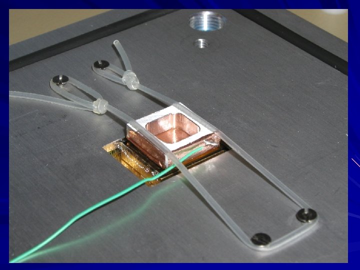
Medi. Pix 2 & Micromegas: apply the ‘naked’ Medi. Pix 2 chip without X-ray convertor! 55 Fe Cathode (drift) plane Micromegas Drift space: 15 mm Baseplate Medi. Pix 2 pixel sensor Brass spacer block Printed circuit board Aluminum base plate Very strong E-field above (CMOS) Medi. Pix!
He/Isobutane 80/20 Modified Medi. Pix 14 mm δ-ray! Efficiency for detecting single electrons: < 95 % Grid. Pix: the electronic bubble chamber
Integrate GEM/Micromegas and pixel sensor: In. Grid ‘GEM’ ‘Micromegas’ ‘wafer post processing’ by Univ. of Twente, MESA+ approved VICI proposal ‘there is plenty of room at the top’
Processing In. Grids Strips Litho. 50 µm SU 8 UV Exposure 0. 8 µm Al Holes Litho. Suspended membrane 50 µm above the wafer Development
Prototypes Hex / Pillars 19 different fields of 15 mm Ø 2 bonding pads / fields Square / Walls Square / Pillars
Energy resolution in Argon Iso. C 4 H 10 80/20 • Observation of two lines: Kα @ 5. 9 ke. V Kβ @ 6. 4 ke. V • FWHM of the Kα distribution 16. 7 % • Gain fluctuations < 5% Very good energy resolution: Very precise dimensions d < 0. 1 μm
Gains in Argon / CO 2 mixtures offers good ageing properties (GOSSIP gas) Gain of 104 reachable in Argon CO 2 80/20 Ageing studies in a reasonable amount of time (intense X-rays source)
Other applications of Grid. Pix: - μ-TPC - Transition Radiation Detectors - GOSSIP: tracker for intense radiation environment
MIP In. Grid Cathode foil CMOS chip ‘slimmed’ to 30 μm CMOS pixel array Drift gap: 1 mm Max drift time: 16 ns GOSSIP: Gas On Slimmed SIlicon Pixels new vertex detector!
Essentials of GOSSIP: • Generate charge signal in gas instead of Si (e-/ions versus e-/holes) • Amplify # electrons in gas (electron avalanche versus FET preamps) Then: • No radiation damage in depletion layer or pixel preamp FETs • No power dissipation of preamps • No detector bias current • Ultralight detection layer (Si foil)
Aging test (remember MSGCs…. !) • ratio of anode surface: thin wire surface versus anode plane (~20 x) • low gas gain due to fast signal and low source capacity (~20 x) At X-ray source (PANalytical) With standard Ar/Methane 90/10 mixture: Equivalent of 3 years Super LHC @ 2 cm from beam pipe
Next Grid. Pix (TPC for ILC) Time. Pix: modify Medi. Pix 2 chip: TDC clock over pixel matrix EUDET (Nikhef-Saclay-Freiburg et al) approved $$$ ! In. Grid Study the geometry influence on Resolution, Gain, Ion back flow: optimise detector geometry Protect the chip from discharges High resistive grid, or separated grid segments Apply In. Grid on Medi. Pix 2, (Time. Pix!), PSI 46 pixel chips GOSSIP repeat aging test with Ar/CO 2 Gossipo: MPW submit for low-noise preamp (Cs = 30 f. F) Test with PSI 46 FE pixel chip equipped with In. Grid
Medi. Pix General Purpose CMOS Pixel chip Grid. Pix Micropattern/pixel readout of gas-filled detectors IC technology X-ray imaging XFEL ESRF TPC for ILC Vertex detecor for ILC & (S)LHC New semiconductors: diamond, Si. C 100 m RASNIK alignment ILC CLIC
Momentum Measurement of muons in the L 3 experiment: Chamber Position Monitoring
Principle of CCD-RASNIK Light Source Lens Coded Mask CCD
CLIC 100 m RASNIK for CLIC Accelerator length: 2 x 15 km Number of elements: 15. 000 Number of ‘ 4 m’ RASNIKs: 15. 000/30. 000 Number of ‘ 100 m’ RASNIKs: 600 Laser zone lens hole dia. 50 mm Ras. Cam 100 m (vacuum tube!)
Pixels for LHC Super LHC ILC !