
Detector Physics of Resistive Plate Chambers Christian Lippmann
Detector Physics of Resistive Plate Chambers Christian Lippmann Work in collaboration with Werner Riegler (CERN) Introduction n Simulation of RPCs n l. Time Resolution l. Efficiency l. Charge Spectra l. Detailed 2 -D simulations of single avalanches l. Rate effects n 23. 05. 2006 Summary Christian Lippmann
Over the last years we have published several articles on RPC detector physics: [0] Rate Effects in Resistive Plate Chambers, Conference proceedings, RPC 2005, Seoul, C. Lippmann, W. Riegler and A. Kalweit [1] Detailed RPC Avalanche Simulations, NIM A 533 (2004) 11 -15, C. Lippmann and W. Riegler [2] The Physics of Resistive Plate Chambers, NIM A 518 (2004) 86 -90, W. Riegler and C. Lippmann [3] Space Charge Effects in Resistive Plate Chambers, CERN-EP/2003 -026, accepted for publication in NIM A, C. Lippmann, W. Riegler [4] Detector Physics of RPCs, Doctoral Thesis, C. Lippmann, May 2003 (CERN, University of Frankfurt) [5] Detector Physics and Simulation of Resistive Plate Chambers , NIM A 500 (2003) 144 -162, W. Riegler, C. Lippmann, R. Veenhof [6] Induced Signals in Resistive Plate Chambers, NIM A 491 (2002) 258 -271, W. Riegler [7] Signal Propagation, Termination, Crosstalk and Losses in Resistive Plate Chambers, NIM A 481 (2002) 130 -143, W. Riegler, D. Burgarth [8] Detector Physics of Resistive Plate Chambers, Proceedings of IEEE NSS/MIC (2002), C. Lippmann, W. Riegler [9] Static Electric Fields in an Infinite Plane Condenser with One or Three Homogeneous Layers, NIM A 489 (2002) 439 -443, CERN-OPEN-2001 -074, T. Heubrandtner, B. Schnizer, C. Lippmann, W. Riegler Only some of this material is covered in this talk! 23. 05. 2006 Christian Lippmann 2

Introduction 23. 05. 2006 Christian Lippmann 3
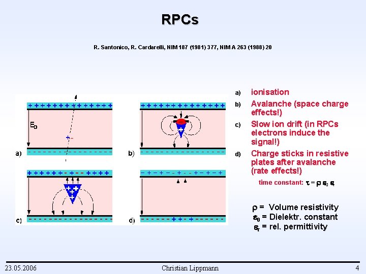
RPCs R. Santonico, R. Cardarelli, NIM 187 (1981) 377, NIM A 263 (1988) 20 a) b) c) d) ionisation Avalanche (space charge effects!) Slow ion drift (in RPCs electrons induce the signal!) Charge sticks in resistive plates after avalanche (rate effects!) time constant: = 0 r = Volume resistivity 0 = Dielektr. constant r = rel. permittivity 23. 05. 2006 Christian Lippmann 4
Working Modes 23. 05. 2006 1) Avalanche mode 2) Streamer mode: photons contribute to the avalanche development 3) Sparks: A conductive vhannel is formed, the electrodes are discharged (Pestov counter) Christian Lippmann 5
Why Resistive Electrodes? u In Parallel Plate Avalanche Chambers (2 parallel metal electrodes) sparks lead to the discharge of whole detector (breakdown): n n 23. 05. 2006 Can destroy electronics Recharging needs time deadtime Christian Lippmann 6
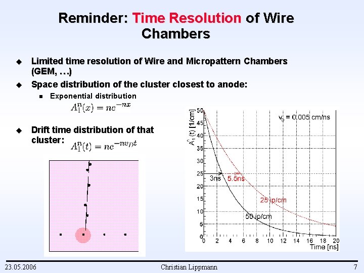
Reminder: Time Resolution of Wire Chambers u u Limited time resolution of Wire and Micropattern Chambers (GEM, …) Space distribution of the cluster closest to anode: n u Exponential distribution Drift time distribution of that cluster: 23. 05. 2006 Christian Lippmann 7
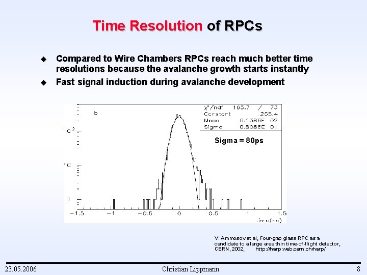
Time Resolution of RPCs u u Compared to Wire Chambers RPCs reach much better time resolutions because the avalanche growth starts instantly Fast signal induction during avalanche development Sigma = 80 ps V. Ammosov et al, Four-gap glass RPC as a candidate to a large area thin time-of-flight detector, CERN, 2002, http: //harp. web. cern. . ch/harp/ 23. 05. 2006 Christian Lippmann 8

Existing RPC technologies Trigger RPCs and Timing RPCs 23. 05. 2006 Christian Lippmann 9
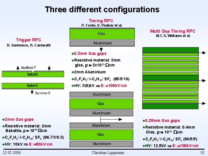
Three different configurations Timing RPC P. Fonte, V. Peskov et al. Multi Gap Timing RPC M. C. S. Williams et al. Trigger RPC R. Santonico, R. Cardarelli u 0. 3 mm Gas gaps u. Resistive material: 3 mm glas, 2 x 1012 cm u 2 mm Aluminium u. C 2 F 4 H 2/ u. HV: u 2 mm i-C 4 H 10/ SF 6 (85/5/10) 3(6)k. V E: 100 k. V/cm Gas gaps u 0. 25 mm u. Resistive material: 2 mm Bakelite, 1010 cm u. C 2 F 4 H 2/ u. HV: u. Resistive material: 0. 4 mm Glas, 1013 cm i-C 4 H 10/ SF 6 (96. 7/3/0. 3) u. C 2 F 4 H 2/ 10 k. V E: 50 k. V/cm 23. 05. 2006 Gas gaps u. HV: Christian Lippmann i-C 4 H 10/ SF 6 (90/5/5) 12. 5 k. V E: 100 k. V/cm 10
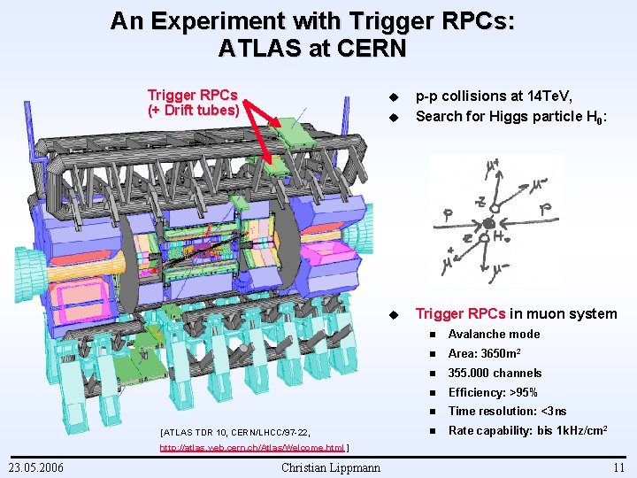
An Experiment with Trigger RPCs: ATLAS at CERN Trigger RPCs (+ Drift tubes) u p-p collisions at 14 Te. V, Search for Higgs particle H 0: u Trigger RPCs in muon system u [ATLAS TDR 10, CERN/LHCC/97 -22, n Avalanche mode n Area: 3650 m 2 n 355. 000 channels n Efficiency: >95% n Time resolution: <3 ns n Rate capability: bis 1 k. Hz/cm 2 http: //atlas. web. cern. ch/Atlas/Welcome. html ] 23. 05. 2006 Christian Lippmann 11
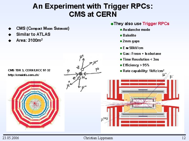
An Experiment with Trigger RPCs: CMS at CERN u u u CMS (Compact Muon Solenoid) Similar to ATLAS Area: 3100 m 2 u. They CMS TDR 3, CERN/LHCC 97 -32 also use Trigger RPCs n Avalanche mode n Bakelite n 2 mm gaps n E 50 k. V/cm n Gas: Freon + Isobutane n Time Resolution < 3 ns n Efficiency > 95% n Rate capability: 1 k. Hz/cm 2 http: //cmsinfo. cern. ch/ 23. 05. 2006 Christian Lippmann 12
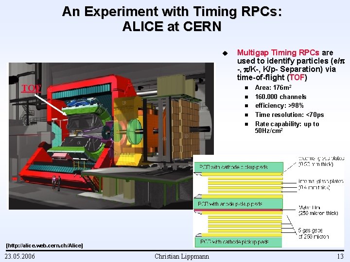
An Experiment with Timing RPCs: ALICE at CERN u TOF Multigap Timing RPCs are used to identify particles (e/ -, /K-, K/p- Separation) via time-of-flight (TOF) n n n Area: 176 m 2 160. 000 channels efficiency: >98% Time resolution: <70 ps Rate capability: up to 50 Hz/cm 2 [http: //alice. web. cern. ch/Alice] 23. 05. 2006 Christian Lippmann 13

Motivation for our work on RPCs 23. 05. 2006 Christian Lippmann 14
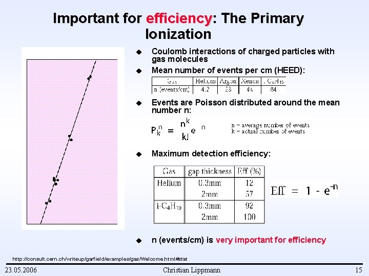
Important for efficiency: The Primary Ionization u u Coulomb interactions of charged particles with gas molecules Mean number of events per cm (HEED): u Events are Poisson distributed around the mean number n: u Maximum detection efficiency: u n (events/cm) is very important for efficiency http: //consult. cern. ch/writeup/garfield/examples/gas/Welcome. html#stat 23. 05. 2006 Christian Lippmann 15
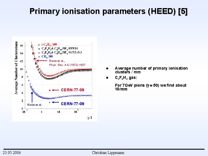
Primary ionisation parameters (HEED) [5] Rieke et al. , Phys. Rev. A 6 (1972) 1507 n n CERN-77 -09 Rieke et al. 23. 05. 2006 Average number of primary ionisation clusters / mm C 2 F 4 H 2 gas: For 7 Ge. V pions ( 50) we find about 10/mm CERN-77 -09 Christian Lippmann
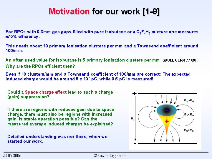
Motivation for our work [1 -9] For RPCs with 0. 3 mm gas gaps filled with pure Isobutane or a C 2 F 4 H 2 mixture one measures 75% efficiency. This needs about 10 primary ionisation clusters per mm and a Townsend coefficient around 100/mm. An often used value for Isobutane is 5 primary ionisation clusters per mm Why are the RPCs efficient then? [SAULI, CERN 77 -09]. Even if 10 clusters/mm and a Townsend coefficient of 100/mm are correct: The expected induced charge would be around 5 x 10⁷ p. C, while 0. 5 p. C is measured! Could a Space charge effect lead to such a charge (gain) suppression? If there are regions with reduced gain due to space charge, there must also be regions with increased gain. Is stable operation possible? Can the measured average induced charges be explained? Detailed understanding was nor there, when we started our work. 23. 05. 2006 Christian Lippmann
Simulation of RPCs Procedure and Results 23. 05. 2006 Christian Lippmann 18
Simulation procedure: One dimensional simulation [5] 1. 2. 3. 4. 5. u u u The gas gap is divided into several steps. The primary clusters are distributed onto the steps. The charges in the gas gap are multiplied and drifted towards the anode. The induced signal is calculated. Steps 3 – 4 are repeated until all electrons have left the gas gap. No Diffusion No Space Charge Effect No Photons 1. 5 D Simulation 23. 05. 2006 Christian Lippmann
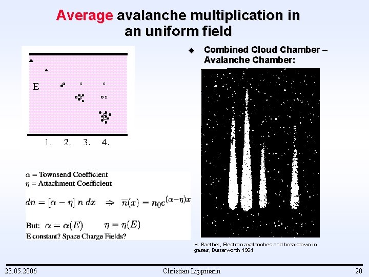
Average avalanche multiplication in an uniform field u Combined Cloud Chamber – Avalanche Chamber: H. Raether, Electron avalanches and breakdown in gases, Butterworth 1964 23. 05. 2006 Christian Lippmann 20
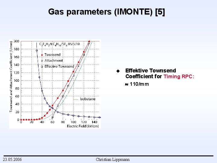
Gas parameters (IMONTE) [5] u 23. 05. 2006 Effektive Townsend Coefficient for Timing RPC: 110/mm Christian Lippmann
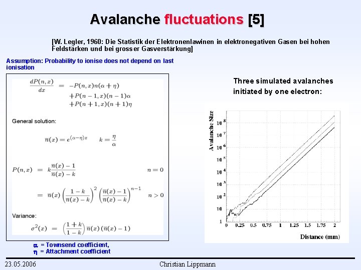
Avalanche fluctuations [5] [W. Legler, 1960: Die Statistik der Elektronenlawinen in elektronegativen Gasen bei hohen Feldstärken und bei grosser Gasverstärkung] Assumption: Probability to ionise does not depend on last ionisation Three simulated avalanches initiated by one electron: = Townsend coefficient, = Attachment coefficient 23. 05. 2006 Christian Lippmann
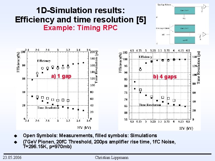
1 D-Simulation results: Efficiency and time resolution [5] Example: Timing RPC a) 1 gap u u 23. 05. 2006 b) 4 gaps Open Symbols: Measurements, filled symbols: Simulations (7 Ge. V Pionen, 20 f. C Threshold, 200 ps amplifier rise time, 1 f. C Noise, T=296. 15 K, p=970 mb) Christian Lippmann
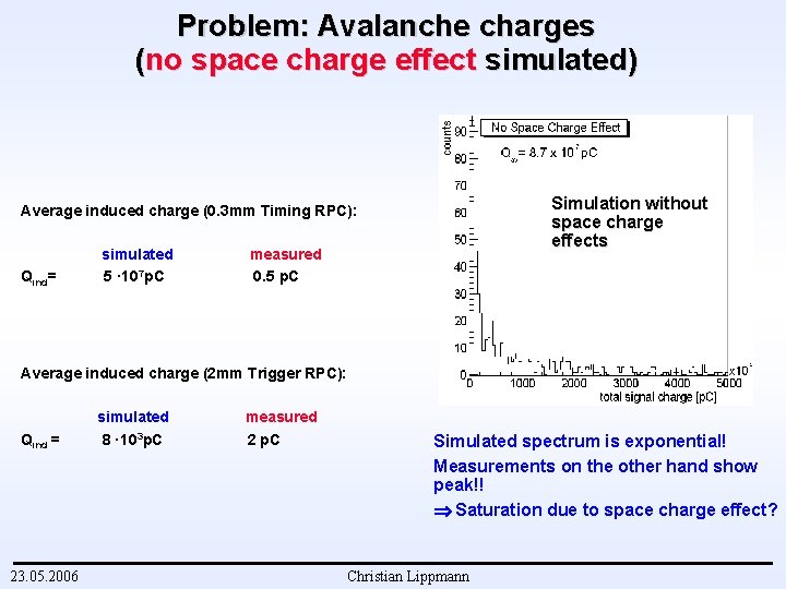
Problem: Avalanche charges (no space charge effect simulated) Simulation without space charge effects Average induced charge (0. 3 mm Timing RPC): Qind= simulated 5 · 107 p. C measured 0. 5 p. C Average induced charge (2 mm Trigger RPC): Qind = 23. 05. 2006 simulated 8 · 103 p. C measured 2 p. C Simulated spectrum is exponential! Measurements on the other hand show peak!! Saturation due to space charge effect? Christian Lippmann
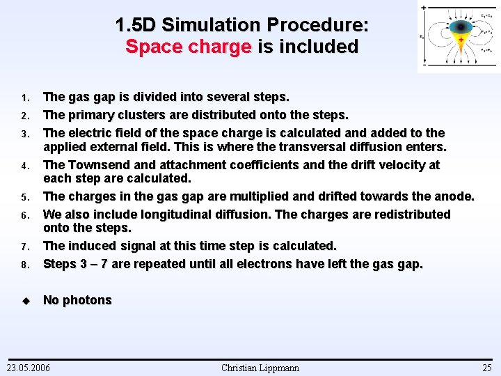
1. 5 D Simulation Procedure: Space charge is included 8. The gas gap is divided into several steps. The primary clusters are distributed onto the steps. The electric field of the space charge is calculated and added to the applied external field. This is where the transversal diffusion enters. The Townsend attachment coefficients and the drift velocity at each step are calculated. The charges in the gas gap are multiplied and drifted towards the anode. We also include longitudinal diffusion. The charges are redistributed onto the steps. The induced signal at this time step is calculated. Steps 3 – 7 are repeated until all electrons have left the gas gap. u No photons 1. 2. 3. 4. 5. 6. 7. 23. 05. 2006 Christian Lippmann 25
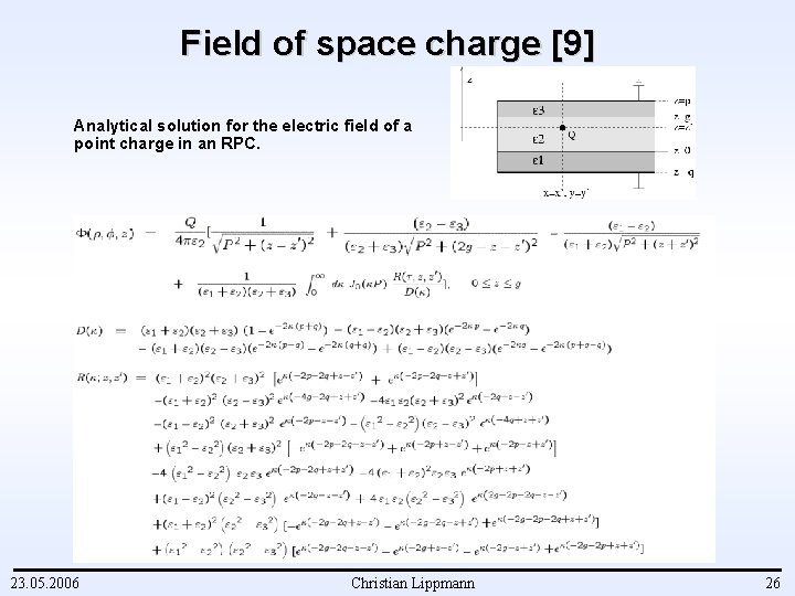
Field of space charge [9] Analytical solution for the electric field of a point charge in an RPC. 23. 05. 2006 Christian Lippmann 26
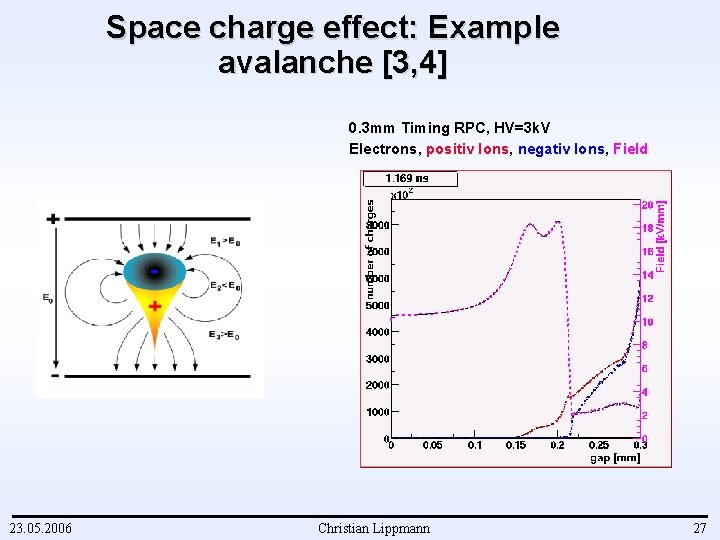
Space charge effect: Example avalanche [3, 4] 0. 3 mm Timing RPC, HV=3 k. V Electrons, positiv Ions, negativ Ions, Field 23. 05. 2006 Christian Lippmann 27
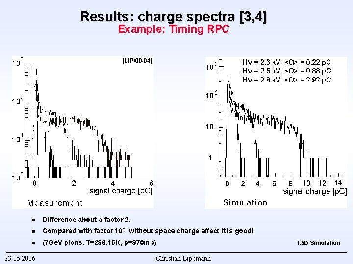
Results: charge spectra [3, 4] Example: Timing RPC [LIP/00 -04] n Difference about a factor 2. n Compared with factor 107 without space charge effect it is good! n (7 Ge. V pions, T=296. 15 K, p=970 mb) 23. 05. 2006 Christian Lippmann 1. 5 D Simulation
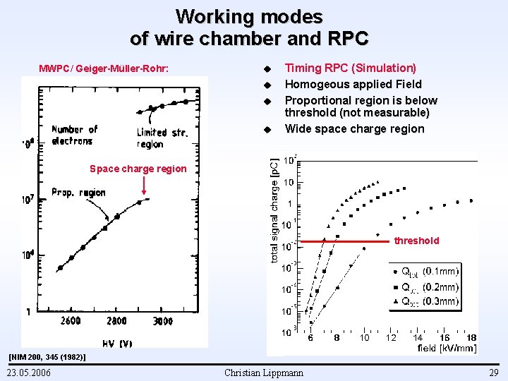
Working modes of wire chamber and RPC MWPC/ Geiger-Müller-Rohr: u u Timing RPC (Simulation) Homogeous applied Field Proportional region is below threshold (not measurable) Wide space charge region Space charge region threshold [NIM 200, 345 (1982)] 23. 05. 2006 Christian Lippmann 29
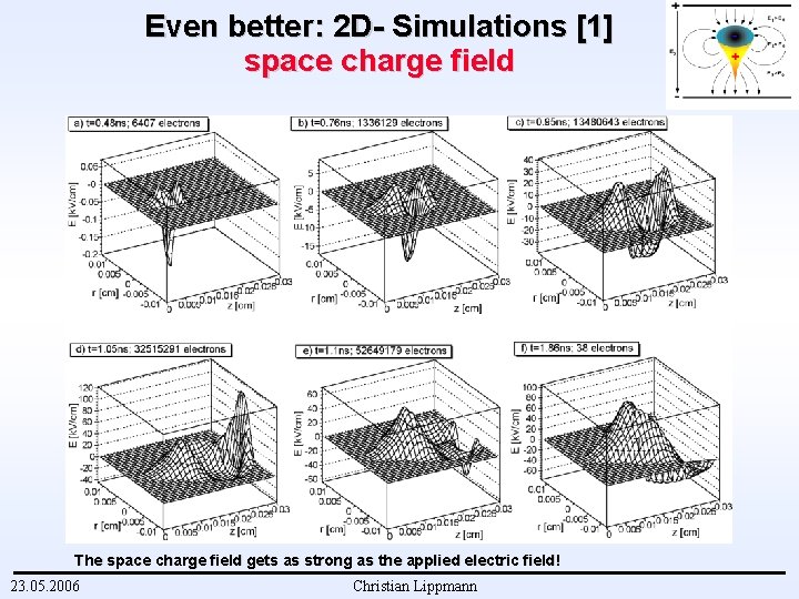
Even better: 2 D- Simulations [1] space charge field The space charge field gets as strong as the applied electric field ! 23. 05. 2006 Christian Lippmann
Rate effects [0] Cause Simulation procedure and Results 23. 05. 2006 Christian Lippmann 31
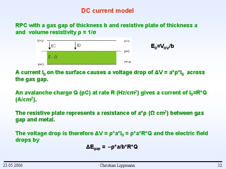
DC current model RPC with a gas gap of thickness b and resistive plate of thickness a and volume resistivity ρ = 1/σ E 0=VHV/b A current I 0 on the surface causes a voltage drop of ΔV = a*ρ*I 0 across the gas gap. An avalanche charge Q (p. C) at rate R (Hz/cm 2) gives a current of I 0=R*Q (A/cm 2). The resistive plate represents a resistance of a*ρ (Ω cm 2) between gas gap and metal. The voltage drop is therefore ΔV = ρ*a*I 0 = ρ*a*R*Q and the electric field drops by ΔEgap = –ρ*a/b*R*Q 23. 05. 2006 Christian Lippmann 32
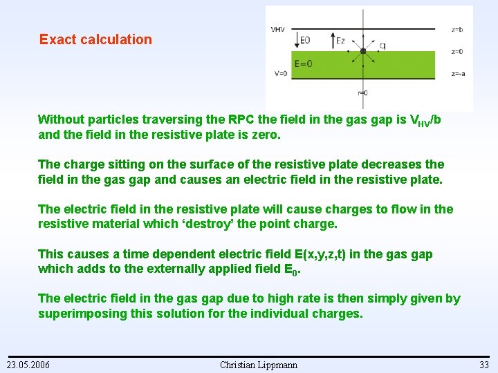
Exact calculation Without particles traversing the RPC the field in the gas gap is V HV/b and the field in the resistive plate is zero. The charge sitting on the surface of the resistive plate decreases the field in the gas gap and causes an electric field in the resistive plate. The electric field in the resistive plate will cause charges to flow in the resistive material which ‘destroy’ the point charge. This causes a time dependent electric field E(x, y, z, t) in the gas gap which adds to the externally applied field E 0. The electric field in the gas gap due to high rate is then simply given by superimposing this solution for the individual charges. 23. 05. 2006 Christian Lippmann 33
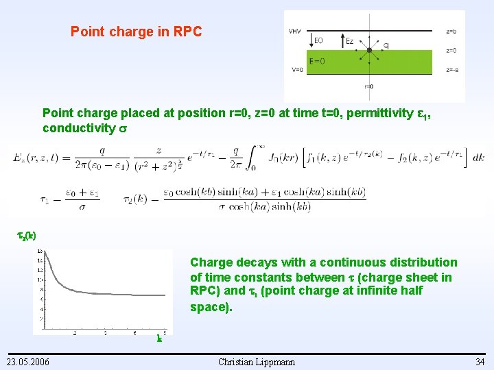
Point charge in RPC Point charge placed at position r=0, z=0 at time t=0, permittivity ε 1, conductivity 2(k) Charge decays with a continuous distribution of time constants between (charge sheet in RPC) and 1 (point charge at infinite half space). k 23. 05. 2006 Christian Lippmann 34
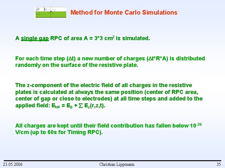
Method for Monte Carlo Simulations A single gap RPC of area A = 3*3 cm 2 is simulated. For each time step ( t) a new number of charges ( t*R*A) is distributed randomly on the surface of the resistive plate. The z-component of the electric field of all charges in the resistive plates is calculated at always the same position (center of RPC area, center of gap or close to electrodes) at all time steps and added to the applied field: Etot = E 0 + Ez(r, z, t). All charges are kept until their field contribution has fallen below 10 -26 V/cm (up to 60 s for Timing RPC). 23. 05. 2006 Christian Lippmann 35
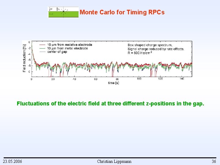
Monte Carlo for Timing RPCs 2 Fluctuations of the electric field at three different z-positions in the gap. 23. 05. 2006 Christian Lippmann 36
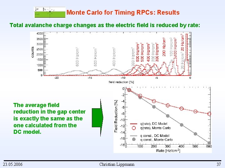
Monte Carlo for Timing RPCs: Results Total avalanche charge changes as the electric field is reduced by rate: The average field reduction in the gap center is exactly the same as the one calculated from the DC model. 23. 05. 2006 Christian Lippmann 37
Summary / Conclusions RPCs are used heavily in high energy physics experiments: • 3650 m 2 Trigger RPCs in ATLAS, • 176 m 2 Timing RPCs in ALICE. The detector physics (time resolution, efficiency, charge spectra) are well understood. Space charge effects can be calculated by using the exact solutions for the electric field of a point charge in the gas gap of an RPC. A strong space charge effect is always present (different than for MWPCs). Rate effects in RPCs can be calculated by using the exact time dependend solutions for the electric field of a point charge on the resistive plate of an RPC. Rate effects: The electric field fluctuates due to the particle flux around a mean value which is equal to the value derived with a simple ohmic law model. 23. 05. 2006 Christian Lippmann 38
- Slides: 38