Detailed Design Review P 20362 The Balls of

Detailed Design Review P 20362 - The Balls of Fury

Table of Contents ● ● ● ● ● Team Vision for Detailed Design Phase Progress Report Designs Analysis Bill of Material Test Plans Risk Assessment Engineering Requirements Design Review Materials Plans for MSD II

Customer Requirements

Engineering Requirements

Accomplished So far Phase I ● ● Worked with customer to clarify PRP Developed and documented ERs and CRs Defined member roles and team norms Documented potential risks and drafted counteractions Phase II ● ● ● Compared potential concepts for modularity Created functional decomposition Laid out system level flow diagrams Documented alternatives for product functions and compared using Pugh charts Updated risk assessment document with mitigation actions Phase III ● ● ● Developed proof-ofconcept style drawings for three different modularity concepts to make final decision Compiled BOMs for electrical and mechanical systems Drafted test plans for high-risk issues and verification of ERs Developed complete schematic based on P 3 -ROC Met with external stakeholders Phase IV ● ● ● Selected final modularity design Generated drawings and 3 D models Developed electrical plans for accommodating Stern Spike Selected locking method for holding modular pieces Placed orders for most non-donated material needed to begin assembly Revised 3 D models to represent donated case

Key Decisions ● Pared down ERs and CRs to better define the engineering scope of the project and what the user will be responsible for ● Received customer play-field layout and used it to refine posible supported components ○ 2 x drop target banks, 2 x flipper assemblies, 2 x kicker assemblies, 8 x rollover switches, 3 x pop bumpers, 1 x spring-loaded ball launcher, 4 x stationary contact targets, 1 x spinning target ● Decided with Professors Wellin and Jacobs to move forward assuming the use of the P 3 ROC architecture with a less detailed backup flow diagram for the Spike ● Chose final modularity concept and moved forward with more detailed 3 D modeling

Customer Design # Game Elements Quantity 1 Flippers 2 2 Slingshot Kickers 2 3 Drop Target Banks 2 4 Rollover Switches 8 5 Pop-Bumpers 3 6 Ball Launcher 1 7 Stationary Target 4 8 Spinning Target 1

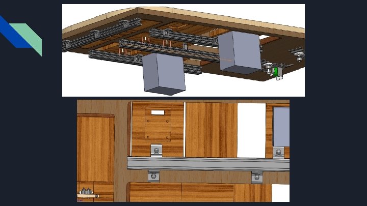
Final Playfield Design Cont. ● Modular playfield ○ 0. 75” X 42. 0” X 20. 25” ○ Red Oak Plywood ● Slotted playfield ○ 3 Columns and 1 Row ● Bail guide rails added ○ 0. 75” X 0. 5” “ X Random Length ○ Red Oak Board ● Modular Blocks ○ 3 D printed in PLA

Final Playfield Design Cont. Pros: ● ● ● Modular blocks can account for all game elements Game elements can be placed anywhere within the slot Approximately 16 game elements spaces available Cons: ● ● ● Drop target assembly can only be placed vertically or horizontally Need to make custom parts for each element Cannot implement custom ball path shapes on top of field

Pop Pumper Modular Block Single Drop Target

Modular Block - Rollover Switches

Analysis

Cable Management Techniques ● ● ● A combination of DIN rails and DIN blocks will be used to break out 48 V, 12 V, and 5 V busses throughout the cabinet The use of DIN parts will allow us to minimize the number of cables coming through the backboard cable cutout Cable raceways will be used to keep the inside of the cabinet organized and easy to maintain

Cable Management ● The wiring bundles will be color coded to make it easier for future teams to work on the prototype cabinet ○ ○ ○ ○ ● 48 VDC: Red 12 VDC: Orange 5 VDC: Yellow Ground: Black Pop Bumper Switch: Blue, blue/white Pop Bumper Coil: Pink, pink/white Targets/Switching Elements: Green, green/white GPIO: White Each 3 D-printed insert will have a designated raceway running to the slot of the playfield
")
P 3 -ROC vs Stern SPIKE Stern Spike ● ● ● Free (Via Donation) Documentation Proprietary Uses Stern node boards for connection MPF compatibility errors more volatile May have to swap software framework P 3 -ROC ● ● $175 Documentation Online Will have to utilize SW-16 and PD-16 boards for connection MPF compatibility errors not as volatile
 operation on a configuration file ○ ●")
Electrical/Software Systems ● MPF (Mission Pinball Framework) operation on a configuration file ○ ● MPF will be running on a Raspberry Pi Model 4 B ○ ● ● This configuration file is responsible for communicating to the CPU what to expect in terms of game configurations and pinball machine parts. The Pi is responsible for communicating to the CPU and an external LCD to display all visual functionalities of our pinball machine. Our CPU if chosen to be the P 3 -ROC will use serial communication to interface with SW 16 and PD-16 boards Our CPU if chosen to be the STERN SPIKE will utilize STERN node boards which handle connection between pinball machine peripherals and the CPU.
 Selection ● ● ● Adafruit Industries LLC, 1413 ○ 3 -axis")
Tilt Sensor (Accelerometer) Selection ● ● ● Adafruit Industries LLC, 1413 ○ 3 -axis accelerometer ○ Analog interface ○ +/- 200 [g] sensing range ○ Breakout board available Low price point ○ $24. 95 (Digi-Key at qty 1) In stock from multiple retailers ○ Digi-Key ○ Adafruit ○ Mouser

Software Framework ● ● The software framework of the project will likely remain to be Mission Pinball Framework If given the Stern SPIKE CPU, MPF could potentially remain as the software framework, unless STERN supplies software for configuring Stern SPIKE

Design Layout with SPIKE

Bill of Materials

Test Plans

Device/ER/CR Under Test: ER 4 Tested Condition: ER 4: >= 3 forms of player feedback present Test: Analysis of design before integration, software evaluation Conditions: Final design compiled Pass Criteria: Pass: Design must support 3 <= X <= 5 forms of user feedback Necessary Equipment: All Stern Pinball components, final design plan, controller board selection Steps: Analyze design and proposed equipment list, controller board Compile list of feedback forms provided in design Compare number of feedback forms to ER 4 requirement

Device/ER/CR Under Test: ER 5 Tested Condition: ER 5: Side-to-side tilt trigger activates when machine tilted excessively by user Test: Analysis of selected accelerometer, tilt-testing final assembly Conditions: Accelerometer (outside cabinet), accelerometer mounted inside assembly Pass Criteria: Pass: Accelerometer reports side-to-side tilt exceeding 10 [deg] (marginal), 5 [deg] (ideal) Necessary Equipment: Accelerometer, playfield mounted inside cabinet, I 2 C device to read accelerometer Steps: Connect accelerometer to I 2 C master device (such as Raspberry Pi) Tilt side-to-side through range of angles, monitor data output on master device Fix accelerometer to underside of playfield Mount playfield in cabinet body Title body through range of angles, monitor data output on master device Analyze data to ensure that accelerometer resolution is high enough to give accurate readings in low angle range (0 -20 [deg])

Device/ER/CR Under Test: ER 6 Tested Condition: ER 6: Front-to-back tilt angle of the playfield surface Test: Measure precise angle of playfield from horizontal in cabinet body Conditions: Playfield fixed (or at least resting on supports) inside body in anticipated position Pass Criteria: Pass: With top surface of angled wedge level, angle of playfield surface must be 4. 5 [deg] < X < 9 [deg] (ideally 6. 5 [deg], the traditional value for a pinball machine) Necessary Equipment: Level, angled block, body, playfield surface Steps: Make a triangular wedge block with a corner angle of exactly 6. 5 [in] Place angled block on top of playfield Place level on wedge to measure surface angle of wedge If top surface of the wedge is not within acceptable range, adjust cabinet legs to modify incline

Risk Assessment

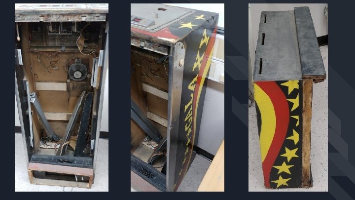
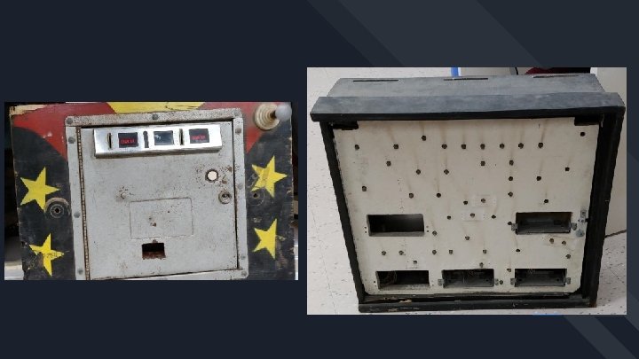
New Risk Items - P 20362 # - New Risk for the Project - 1 Complex geometry of pinball game elements and unknown geometry of Stern parts (Pop-bumpers, Single Drop Targets, Standing Targets, and Switches). 2 Improper wiring of game elements to field and lack of wire management 3 3 D printed modular blocks can potentially introduce rifts in the field and additional friction factor to the pinball path. 4 Integration of modular playfield into the donated cabinet from Bruce 5 Fixing up the cabinet before the end of MSD II phase

New Risk Items - P 20362 # - Actions to Minimize New Risks - 1 Create a preliminary module block(s) that can mount a standard Pop-bumper, single drop target, rollover switch, and stationary targets. 2 Color coding wires to game elements and using a combination of DIN rails and DIN blocks. 3 Use sandpaper with various grits and coat all 3 D printed parts in XTC-3 D. This will give all our 3 D printed parts a a clean and smooth finish. 4 Create a cardboard cutout of modular playfield and we can also CAD up the donated cabinet and insert the 3 D modular playfield. 5 Evaluate areas on the cabinet that need to be replaced. Buy new hardware/ wood (bolts and screws) and try to restore the machine to its original state.

MSD II Preliminary High-Level Schedule ● ● Subsystem Level Preparation ○ Model inherited case in CAD ○ Manufacture preliminary playfield, component modules ○ Develop prototype software Subsystem Level Build & Test ○ Assemble playfield mounting equipment ○ Mount controller boards in cabinet and body ○ Integrate wire management solution ○ Test ability to connect with and control components Systems Level Build, Test & Integrate ○ Resolve any subsystem issues from previous phase ○ System performance verification ○ Complete user documentation Verification & Validation ○ Resolve any remaining issues from previous phase ○ Finalize documentation ○ Prepare for project handoff

Appendices

Project Overview Recap

Complete BOM

Device/ER/CR Under Test: ER 1 Tested Condition: ER 1: >= 95% components must be available for purchase off-the-shelf Test: Component analysis Conditions: Final design verified by Professor Jacobs, George Gomez; part list finalized Pass Criteria: Pass: >= 95% components must be available for purchase off-the-shelf Necessary Equipment: Final design, full component list from Stern Pinball Steps: Analyze design and required components Compile percentage of off-the-shelf components Compare result to ER 1 requirement

Device/ER/CR Under Test: ER 2 Tested Condition: ER 2: >= 7 active game elements Test: System capability assessment, playability test Conditions: Component list finalized from Stern Pinball Pass Criteria: Pass: System is capable of supporting a minimum of (7) components in active play, but not necessarily more than: (2) 4 -bank drop targets, or (10) stationary targets, or (10) pop bumpers Necessary Equipment: Final component list, assembled design Steps: Analyze design to identify potential compatibility issues Ensure that final design meets requirements of ER 2 Assemble final playfield design Test machine with proposed design from customer Test machine with (2) 4 -bank drop target assemblies Test machine with (10) stationary targets Test machine with (10) pop bumpers

Device/ER/CR Under Test: ER 3 Tested Condition: ER 3: System supports the ability to drive >= (2) flippers Test: Analysis of system capabilities (power driver board) Conditions: Final customer layout design, component list finalized from Stern Pinball Pass Criteria: Pass: In customer layout configuration, power delivery board is capable of driving two flippers simultaneously for 3 [s], 10 times in 100 [s] Necessary Equipment: All Stern Pinball components, wiring to connect flippers Steps: Attach (at minimum) two flippers to controller and power driver boards Activate flippers simultaneously, hold for 3 [s] Release flippers, wait for 7 [s] Repeat 10 times

Device/ER/CR Under Test: ER 7 Tested Condition: ER 7: Average time for user to change playfield Test: Measure time for customer to disassemble and reassemble playfield in defined layout Conditions: Customer-defined playfield begins fully-assembled and playable, Professor Jacobs is user Pass Criteria: Pass: User must be able to power off machine, remove all components from board and re-connect all components into original layout, apply power, and return game to original playable state in <= 30 [m] Necessary Equipment: Completed unit with all components as required by customer-defined layout Steps: Remove power from fully-assembled machine in playable state Lift playfield, disconnect and remove all components, set components aside Replace all components in original positions Replace playfield, close lide Re-apply power Measure time required to change playfield

Device/ER/CR Under Test: ER 8 Tested Condition: ER 8: Documentation allows user to interact with playfield without assistance Test: User constructs customer-defined layout without assistance from team Conditions: User (Professor Jacobs) provided with components, machine, layout, documentation Pass Criteria: Pass: User is able to create working playfield as defined by pre-determined layout with no additional instructions/assistance from team Necessary Equipment: Components per layout, user, assembled unit Steps: Remove power from unit Remove all components and shims from playfield Provide user with all necessary components, documentation Observe process of user attempting to construct playfield Modify documentation as necessary based on feedback from user

Device/ER/CR Under Test: Adafruit 1413 Accelerometer Tested Condition: Output voltage of accelerometer lines as user nudges machine, replicating game play Test: With accelerometer mounted on underside of playfield, user nudges machine as in standard play 15 times on each side of the machine while the output signals are recorded Conditions: User Professor Jacobs, body assembled, playfield mounted in body Pass Criteria: N/A: investigative test to determine where to set levels for nudge alarms Necessary Equipment: Assembled body, accelerometer, Raspberry Pi, Oscilloscope Steps: Mount accelerometer to underside of playfield User nudges machine 15 times from each side Record variations in output voltage Compile data, use to determine where to set trigger level for nudge alarm

Design Layout with P 3 -ROC
- Slides: 41