
DETAILED DESIGN REVIEW P 10232 UAV AIRFRAME C





- Slides: 61
DETAILED DESIGN REVIEW P 10232 – UAV AIRFRAME C Daniel Graves – James Reepmeyer – Brian Smaszcz – Alex Funiciello – Michael Hardbarger – Project Lead Engineer Airframe Design Airfoil Design Control Systems
Project Definition Mission Statement: The goal of the UAV Airframe C project is to provide an unmanned aerial platform used for an aerial imaging system. The airframe must support the weight and interfaces for the designed imaging system. The aircraft must be operated remotely and be a viable alternative to current aerial imaging methods. This is a second generation airframe, expanding on the previously laid ground work established by the P 09232 UAV B Senior Design Project.
Risk Management
Customer Needs Key Project Goals: Airframe must be able to carry a fifteen pound payload Easy integration with measurement controls box and different aerial imaging systems Ability to remotely control aircraft and activate payload Ability for flight communication between aircraft and ground relay Aircraft provides twenty minutes of flight time for local area photography Aircraft has the potential to take off and land on site Easy assembly and disassembly of the aircraft for transportation
Lessons Learned From P 09232 The aircraft’s wings sheared off shortly before impact. The failure was determined to be from the bending stress applied to the wings during the banked turned. After analysis, it was concluded that the main fiberglass spar used to support the wing was not selected properly to handle the flight loading. High bend in the wing during flight inhibited the pilot’s control of the aircraft by reducing the effectiveness of the control surfaces.
Design goals based on lessons learned from P 09232 Reduce wingspan (reduced bending moment) Re-enforce wing spar Reduce plane weight Re-evaluate electric propulsion
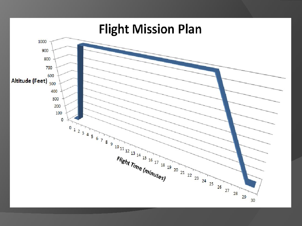
Engineering Specifications The aircraft shall have a maximum weight of 25 lbs without payload (40 lbs gross) The aircraft shall have a flight ceiling of 1000 ft The aircraft shall be able to sustain a flight of at least 40 mph in calm conditions The aircraft shall be capable of stable flight with a 15 lb payload The aircraft shall utilize an open architecture payload interface
Engineering Specifications The aircraft shall provide a mechanical interface to the payload The aircraft shall provide a secure anchoring connection for the photographic instrument payload The aircraft shall provide a secure mounting location for the flight control electronics package (P 10236) The aircraft shall sustain steady flight in a controllable manner for at least 20 minutes The aircraft shall be able to re-launch as soon as it has been re-fueled or re-charged
Engineering Specifications The aircraft shall be able to operate for at least 12 regular flights without needing routine maintenance The aircraft shall be able to take off under its own power from a 1000 ft grass runway The aircraft shall have a sufficiently powerful motor The aircraft shall be able to be transported in a motor vehicle when disassembled The aircraft should be easy to assemble and disassemble by one person The aircraft shall be able to navigate while on the ground
Engineering Specifications The final cost shall be less than the cost of renting a Cessna for a day (~$8000) The aircraft should have similar flight characteristics to a trainer RC plane The wing shall support the plane’s gross weight under +4/-2 G loading The wings shall not become detached from the plane while in flight The wings shall not deflect to a degree that interferes with the operation of the flight control surfaces (will not jam the servos)
Engineering Specifications The propulsion system shall provide uninterrupted, constant power for at least 20 min The landing gear shall hold the plane at an optimal angle of attack while on the ground The servos shall be of sufficient power to control the plane’s control surfaces at speeds up to 50 mph The aircraft shall be structurally sound; no parts shall leave the aircraft while in flight
Airfoil Analysis
Learning from Airframe B Based on Airframe B, worst case would be a wing failure Airframe B was successful in meeting the total lift requirement
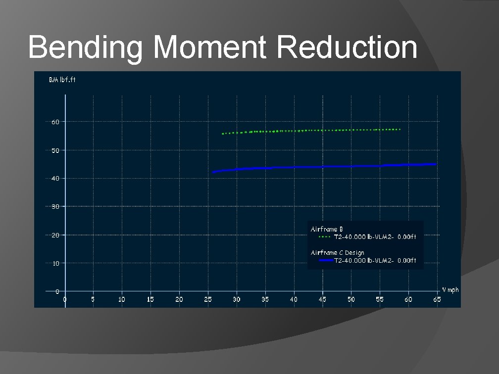
Design Objectives Reduce the moment on the wing by reducing the wing span Provide enough lift to lift the 40 lb plane/payload
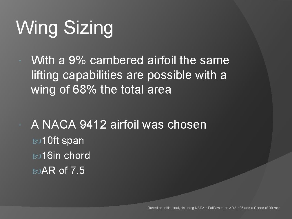
Wing Sizing With a 9% cambered airfoil the same lifting capabilities are possible with a wing of 68% the total area A NACA 9412 airfoil was chosen 10 ft span 16 in chord AR of 7. 5 Based on initial analysis using NASA’s Foil. Sim at an AOA of 6 and a Speed of 30 mph
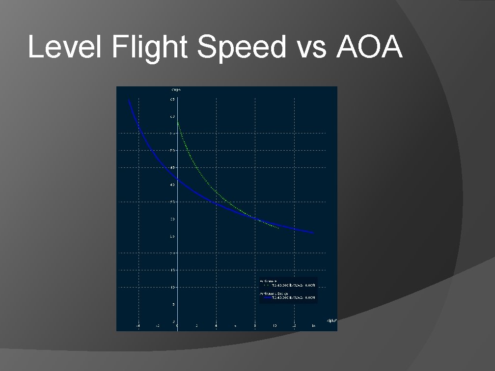
Level Flight Speed vs AOA
Bending Moment Reduction
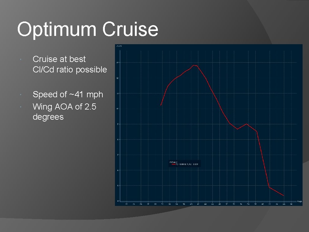
Optimum Cruise at best Cl/Cd ratio possible Speed of ~41 mph Wing AOA of 2. 5 degrees
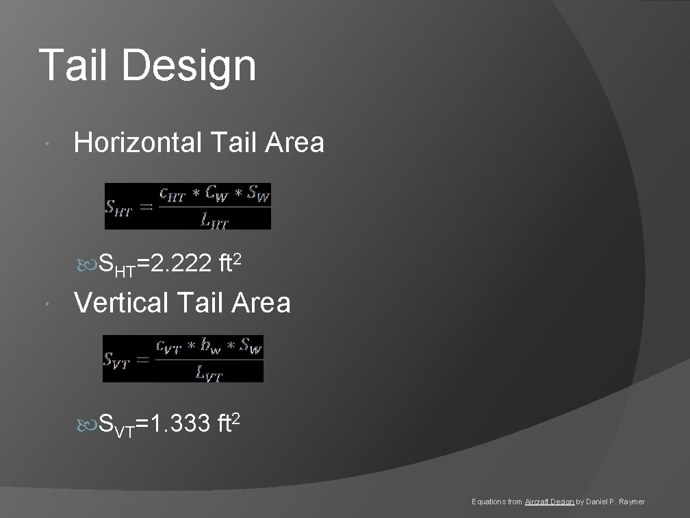
Tail Design Horizontal Tail Area SHT=2. 222 ft 2 Vertical Tail Area SVT=1. 333 ft 2 Equations from Aircraft Design by Daniel P. Raymer
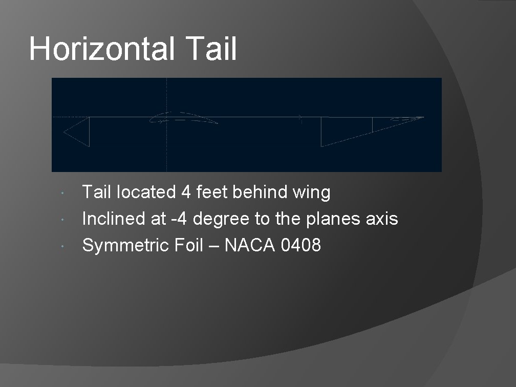
Horizontal Tail located 4 feet behind wing Inclined at -4 degree to the planes axis Symmetric Foil – NACA 0408
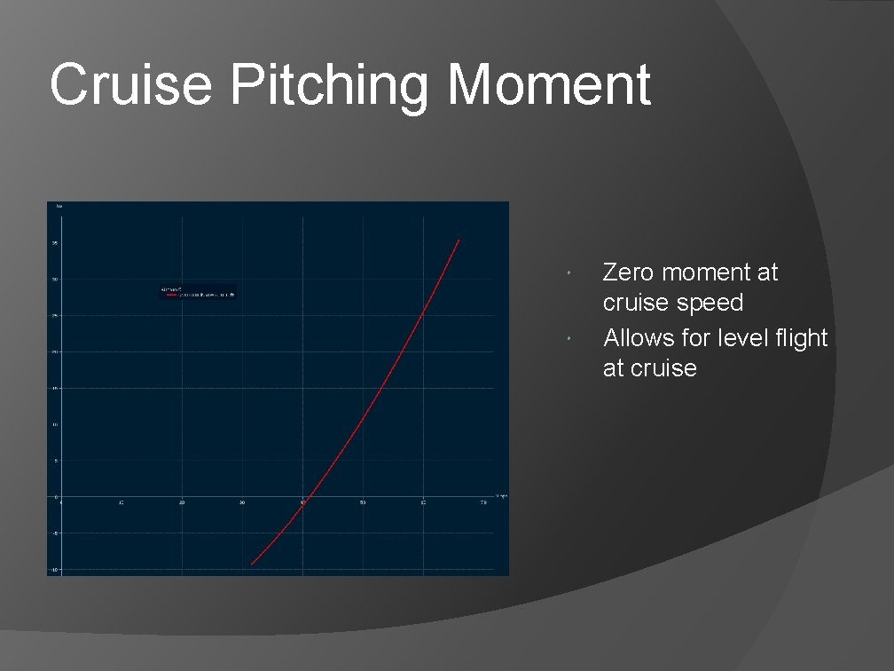
Cruise Pitching Moment Zero moment at cruise speed Allows for level flight at cruise
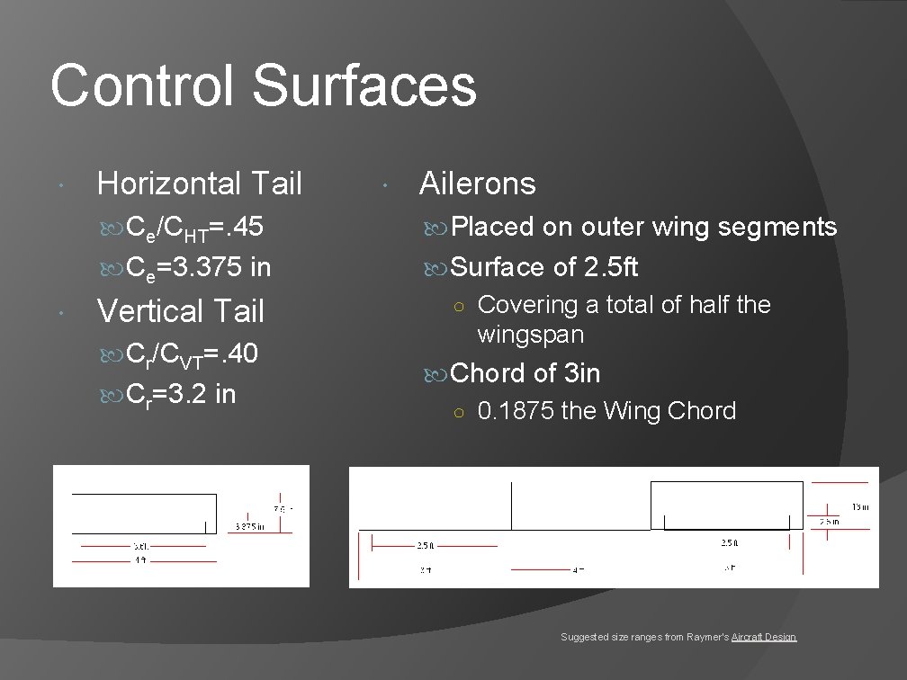
Control Surfaces Horizontal Tail Ailerons Ce/CHT=. 45 Placed on outer wing segments Ce=3. 375 in Surface of 2. 5 ft ○ Covering a total of half the wingspan Vertical Tail Cr/CVT=. 40 Cr=3. 2 in Chord of 3 in ○ 0. 1875 the Wing Chord Suggested size ranges from Raymer’s Aircraft Design
Propulsion Analysis
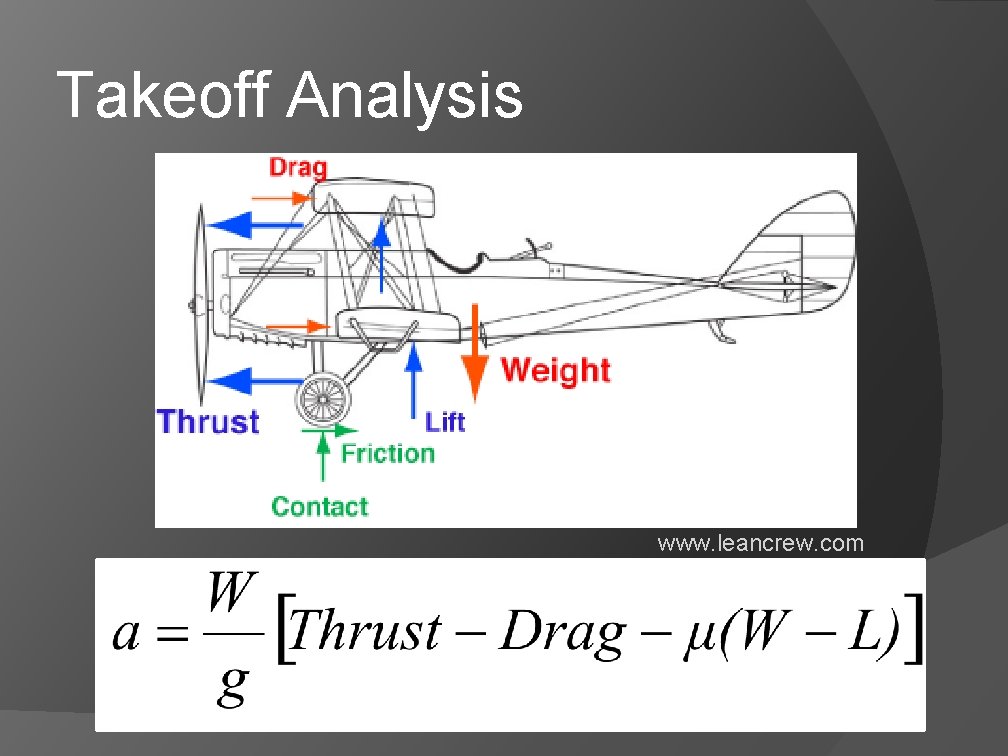
Takeoff Analysis www. leancrew. com
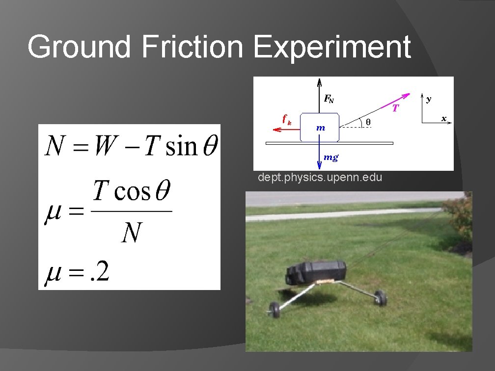
Ground Friction Experiment dept. physics. upenn. edu
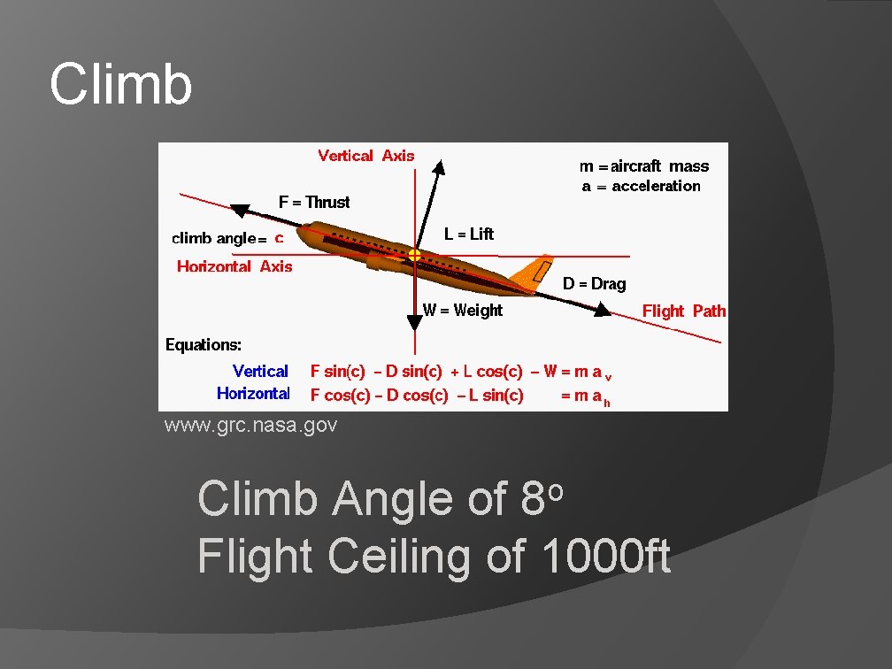
Climb www. grc. nasa. gov o 8 Climb Angle of Flight Ceiling of 1000 ft
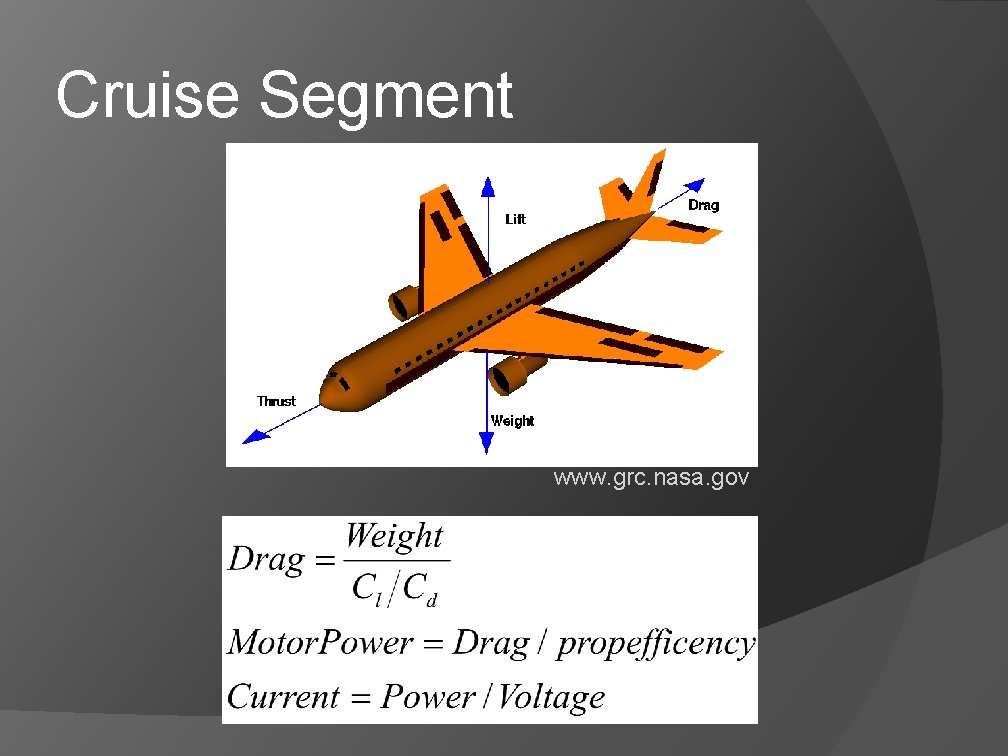
Cruise Segment www. grc. nasa. gov
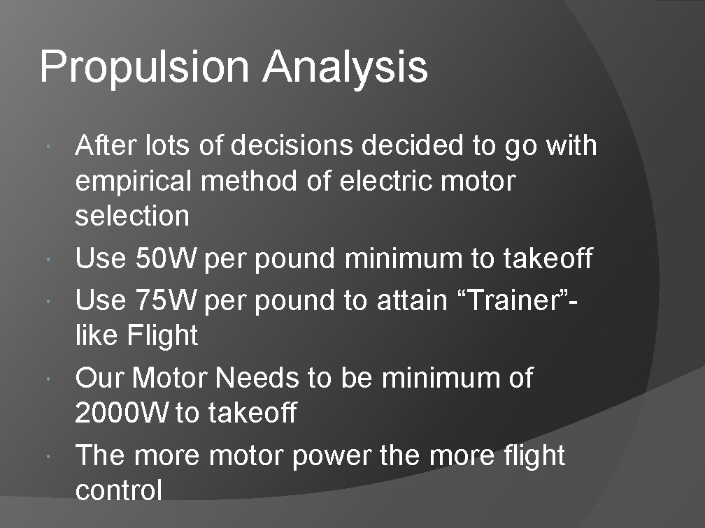
Propulsion Analysis After lots of decisions decided to go with empirical method of electric motor selection Use 50 W per pound minimum to takeoff Use 75 W per pound to attain “Trainer”like Flight Our Motor Needs to be minimum of 2000 W to takeoff The more motor power the more flight control
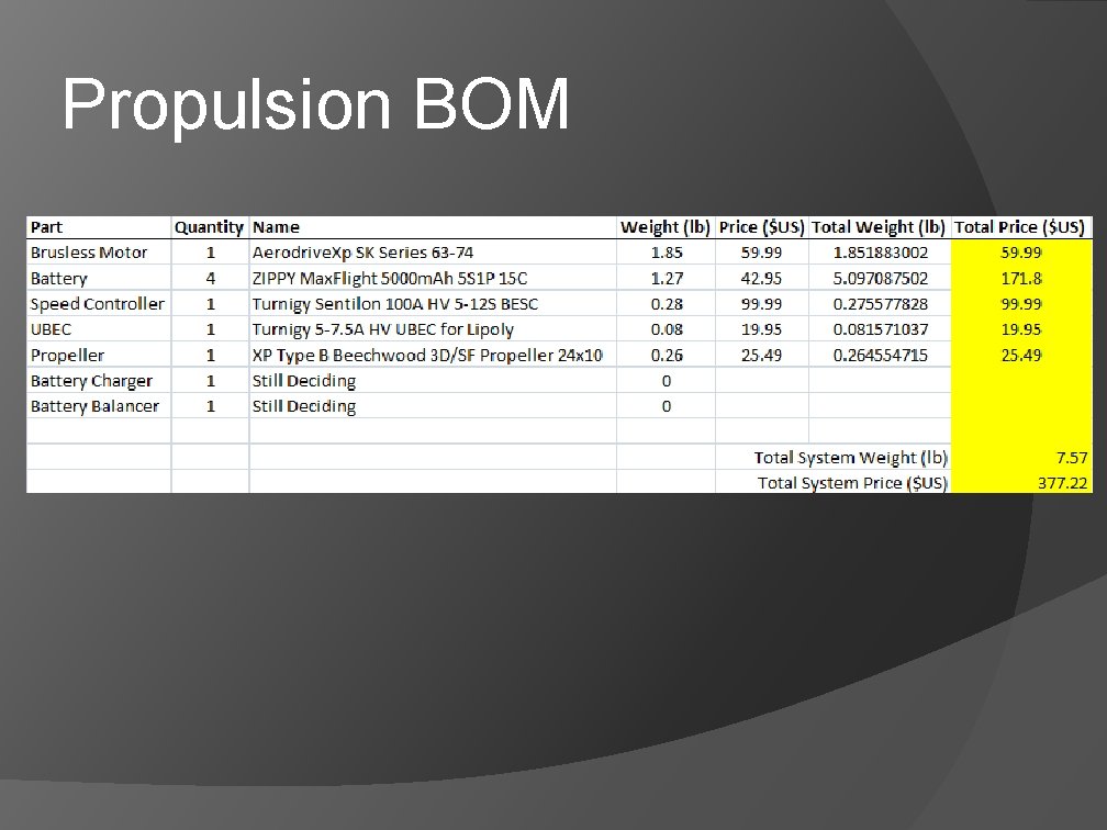
Propulsion BOM
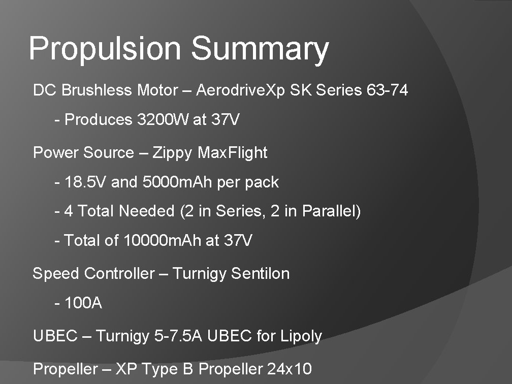
Propulsion Summary DC Brushless Motor – Aerodrive. Xp SK Series 63 -74 - Produces 3200 W at 37 V Power Source – Zippy Max. Flight - 18. 5 V and 5000 m. Ah per pack - 4 Total Needed (2 in Series, 2 in Parallel) - Total of 10000 m. Ah at 37 V Speed Controller – Turnigy Sentilon - 100 A UBEC – Turnigy 5 -7. 5 A UBEC for Lipoly Propeller – XP Type B Propeller 24 x 10
Landing Gear Analysis
Landing Gear Summary Front landing gear used will be the one designed for UAV B, in order to save on cost. Tail landing gear will be an off-the-shelf system designed for large airplanes. Ohio Superstar Maxi Tail Gear (30 -50 lb planes)
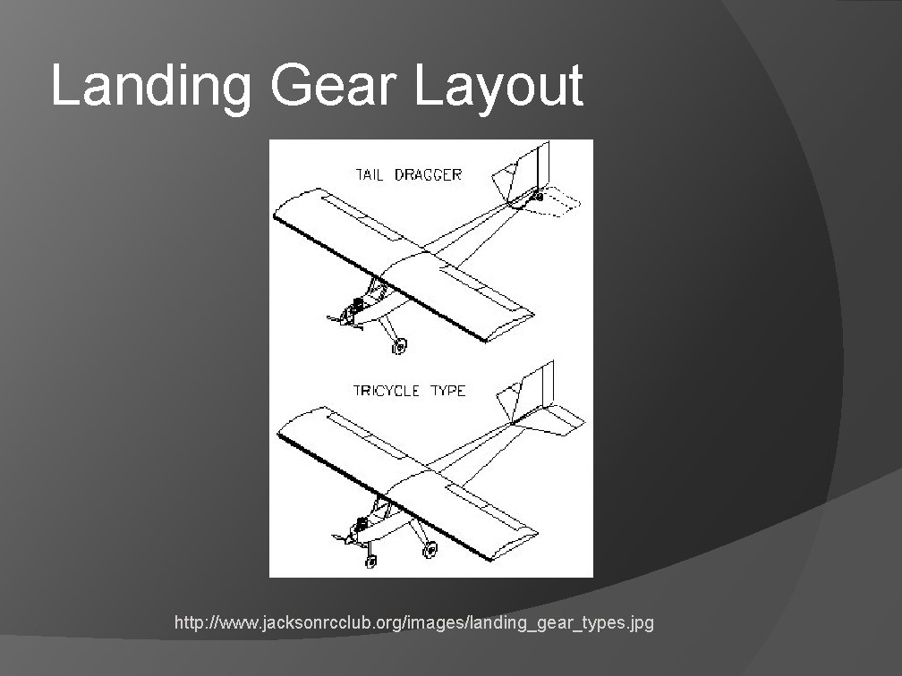
Landing Gear Layout http: //www. jacksonrcclub. org/images/landing_gear_types. jpg
Front Landing Gear Analysis Front landing gear was designed analyzed for UAV B and fitted for UAV C. Since the landing gear was designed for the impact load of a higher weight plane it will work in this application. Detailed analysis and method is unavailable Complete FEA analysis of the part in the future to ensure reliability.
Tail Landing Gear Assembly Tail landing gear was selected as an off-the-shelf system from an online hobby shop. Due to the high weight application and high cost, retractable tail landing gear was not justified. Three possibilities for tail Gear: Ohio Superstar Haigh Super Tail Gear (30 -50 lb plane) Ohio Superstar Maxi Tail Gear (30 -50 lb plane) Sullivan Tail Wheel Bracket (16 -35 lb plane) Information selected from Tower Hobbies. http: //www. towerhobbies. com/
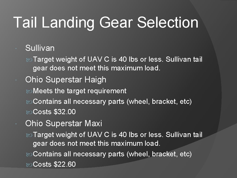
Tail Landing Gear Selection Sullivan Target weight of UAV C is 40 lbs or less. Sullivan tail gear does not meet this maximum load. Ohio Superstar Haigh Meets the target requirement Contains all necessary parts (wheel, bracket, etc) Costs $32. 00 Ohio Superstar Maxi Target weight of UAV C is 40 lbs or less. Sullivan tail gear does not meet this maximum load. Contains all necessary parts (wheel, bracket, etc) Costs $22. 60
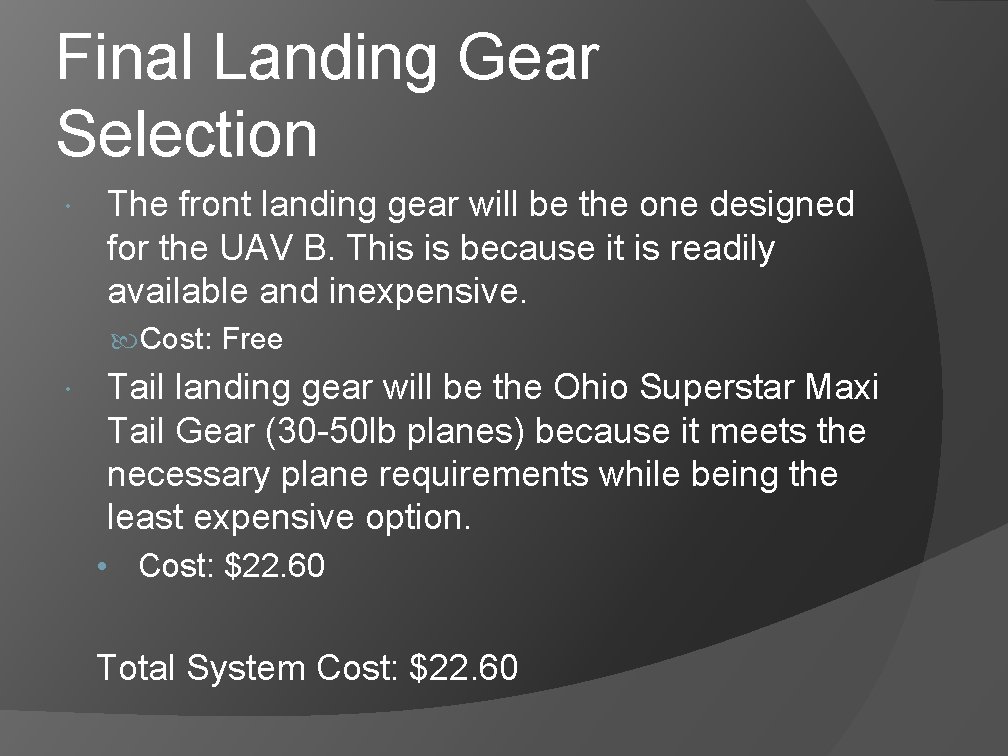
Final Landing Gear Selection The front landing gear will be the one designed for the UAV B. This is because it is readily available and inexpensive. Cost: Free Tail landing gear will be the Ohio Superstar Maxi Tail Gear (30 -50 lb planes) because it meets the necessary plane requirements while being the least expensive option. • Cost: $22. 60 Total System Cost: $22. 60
Main Wing Spar Analysis
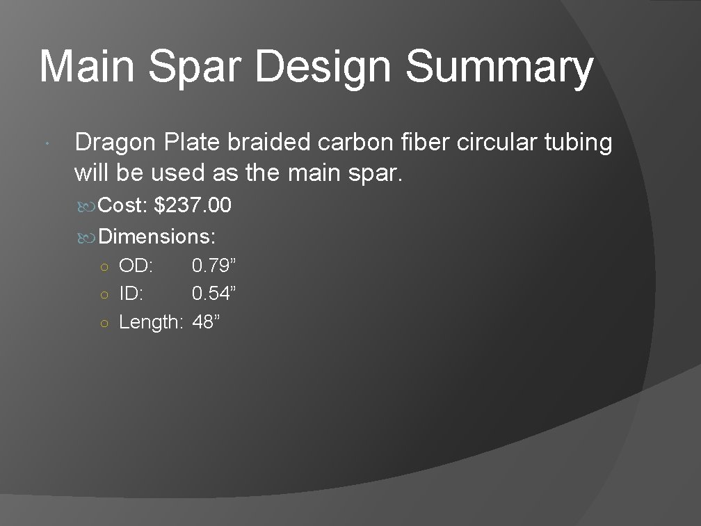
Main Spar Design Summary Dragon Plate braided carbon fiber circular tubing will be used as the main spar. Cost: $237. 00 Dimensions: ○ OD: 0. 79” ○ ID: 0. 54” ○ Length: 48”
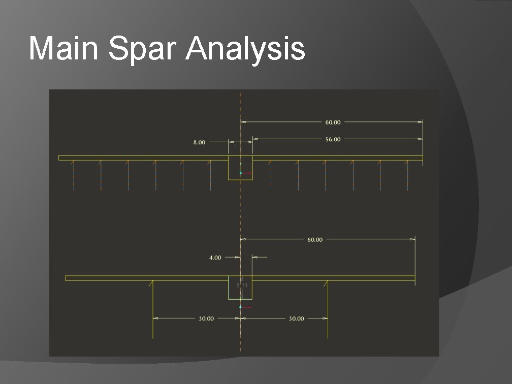
Main Spar Analysis Assumptions At steady, level flight the wing is loaded uniformly across the span. Main spar supports the entire weight of the plane by itself. From the wing root outwards the spar behaves as a cantilevered beam. Normal flight load is 40 lbf Design will be to 5 g acceleration per guidelines in the RCAdvisor’s Model Airplane Design handbook. Due to symmetry, half the wing will be analysis.
Main Spar Analysis Design Considerations Must remain under materials yield strength (elastic region) to avoid permanent deformation. Must not deflect excessively at flight load (less than 1 foot) in order for control surfaces to maintain effectiveness. Must be light in order to keep the weight of the aircraft at a minimum. Must be competitively priced compared to other options.
Main Spar Analysis Materials were selected that are readily available and have associated engineering data provided for analysis. A supplier for fiber glass tube could not be found which supplied the correct spar dimensions as well as the appropriate engineering data for analysis.
Main Spar Analysis
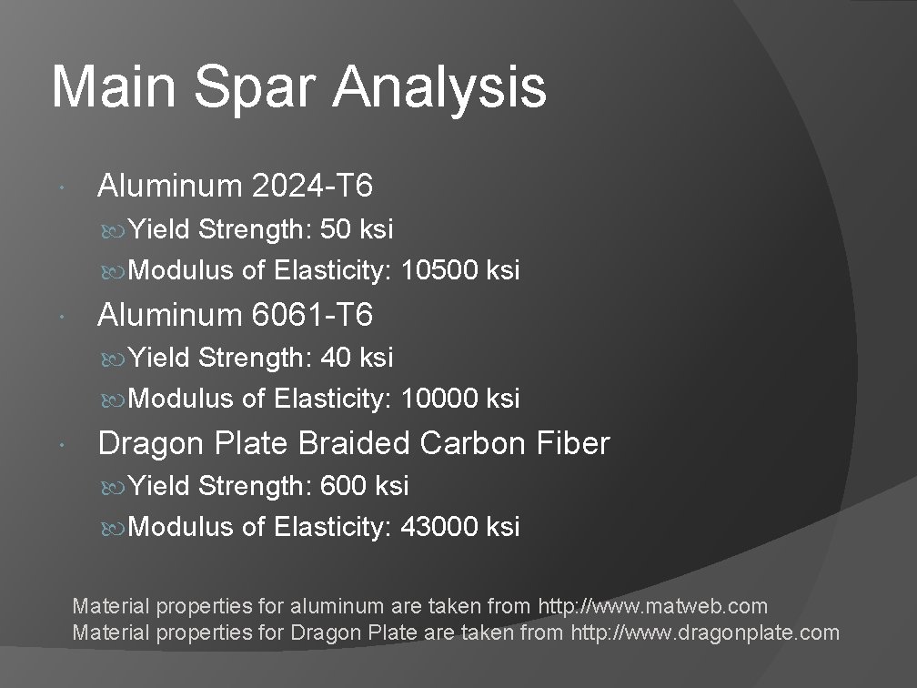
Main Spar Analysis Aluminum 2024 -T 6 Yield Strength: 50 ksi Modulus of Elasticity: 10500 ksi Aluminum 6061 -T 6 Yield Strength: 40 ksi Modulus of Elasticity: 10000 ksi Dragon Plate Braided Carbon Fiber Yield Strength: 600 ksi Modulus of Elasticity: 43000 ksi Material properties for aluminum are taken from http: //www. matweb. com Material properties for Dragon Plate are taken from http: //www. dragonplate. com
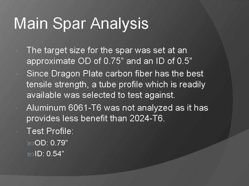
Main Spar Analysis The target size for the spar was set at an approximate OD of 0. 75” and an ID of 0. 5” Since Dragon Plate carbon fiber has the best tensile strength, a tube profile which is readily available was selected to test against. Aluminum 6061 -T 6 was not analyzed as it has provides less benefit than 2024 -T 6. Test Profile: OD: 0. 79” ID: 0. 54”
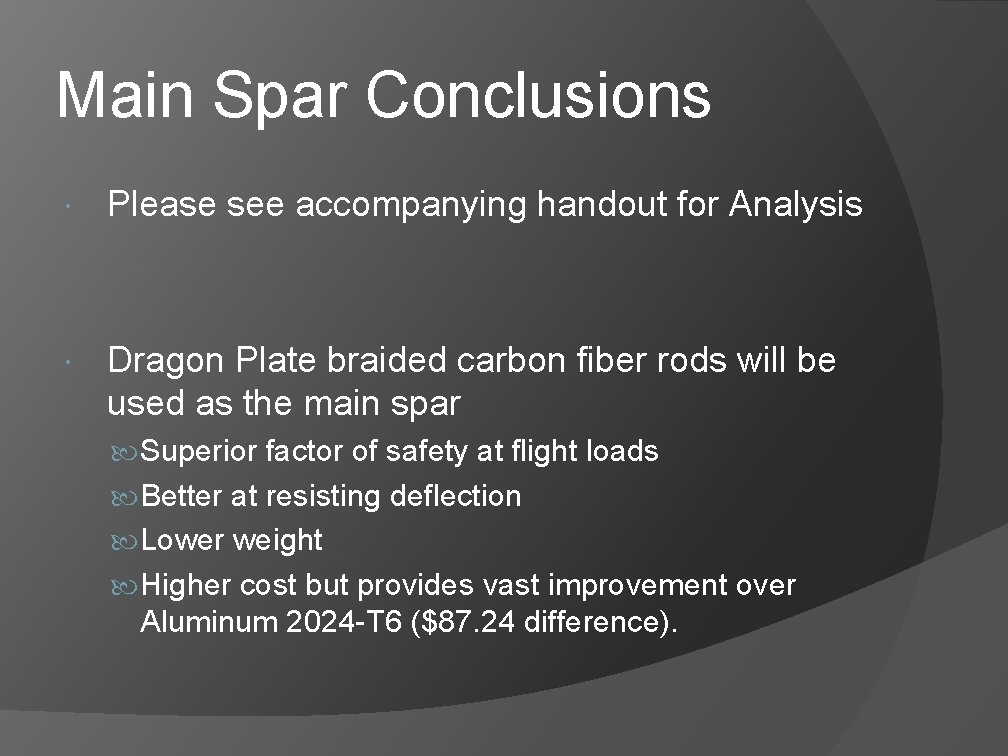
Main Spar Conclusions Please see accompanying handout for Analysis Dragon Plate braided carbon fiber rods will be used as the main spar Superior factor of safety at flight loads Better at resisting deflection Lower weight Higher cost but provides vast improvement over Aluminum 2024 -T 6 ($87. 24 difference).
Airframe and Interface Designs
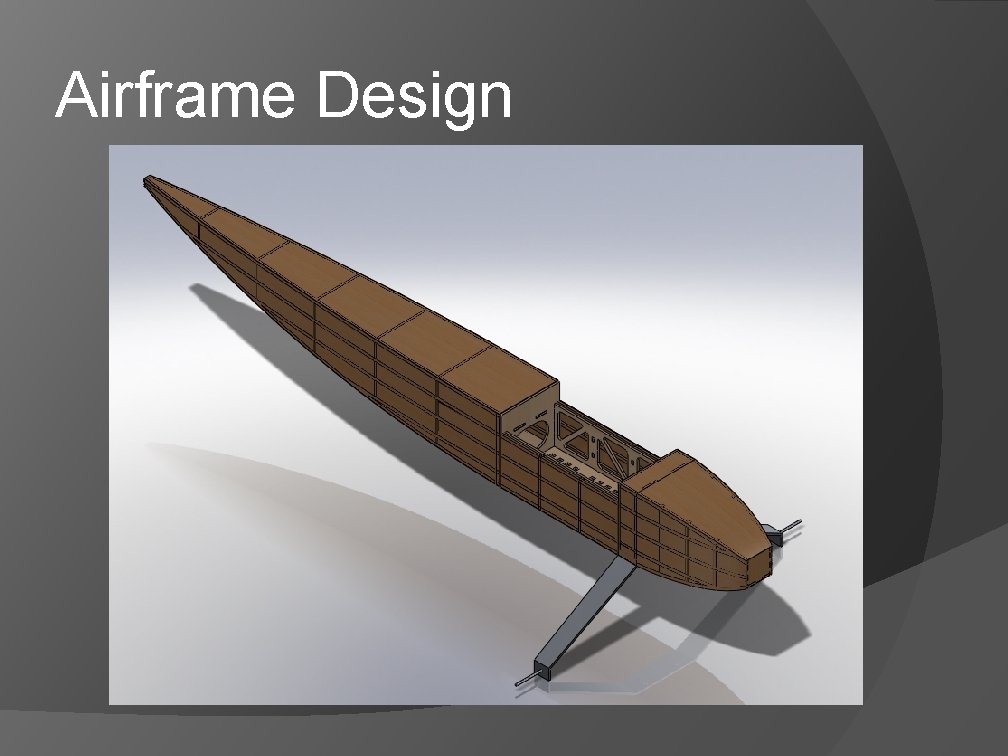
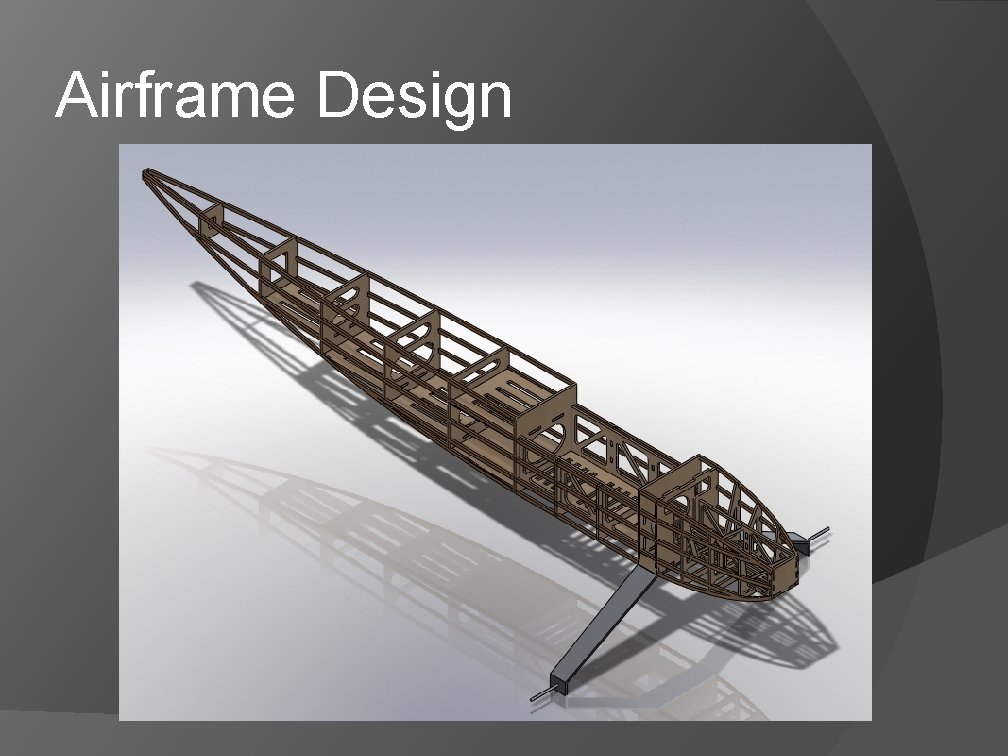
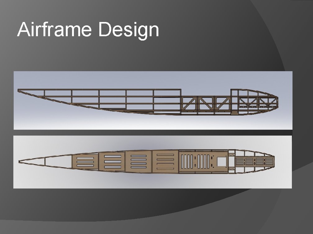
Airframe Design
Airframe Design
Airframe Design
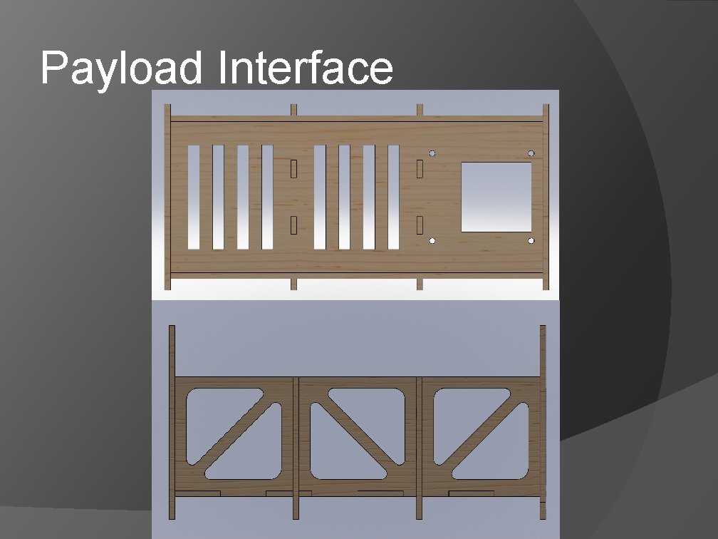
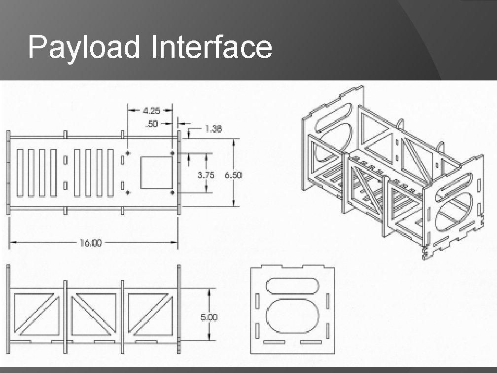
Payload Interface
Payload Interface
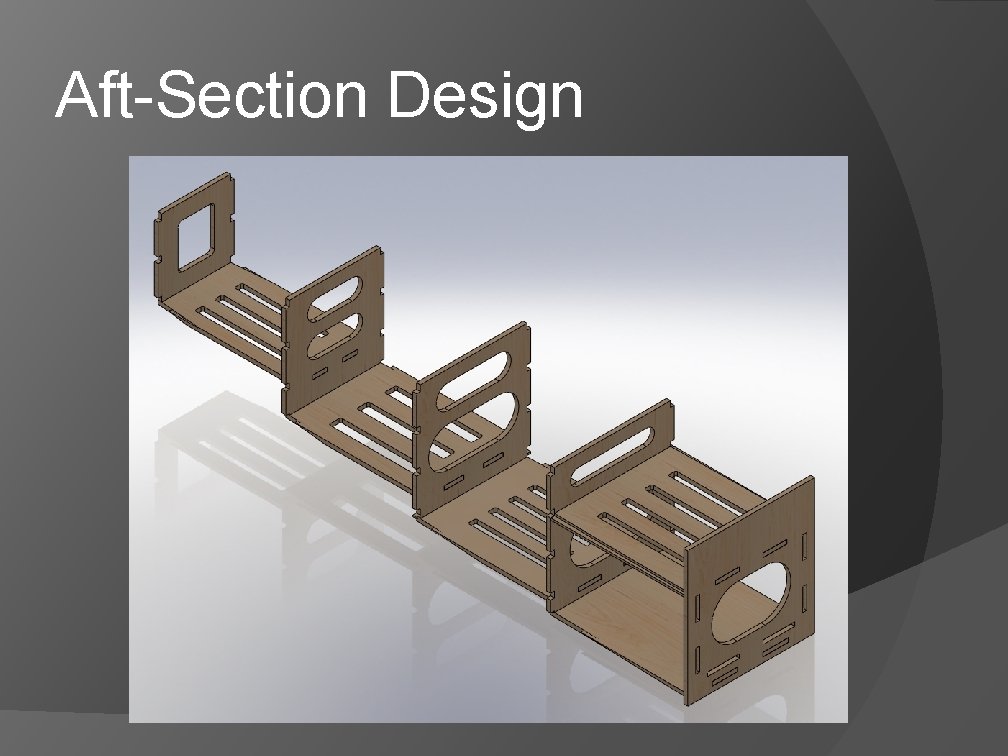
Aft-Section Design
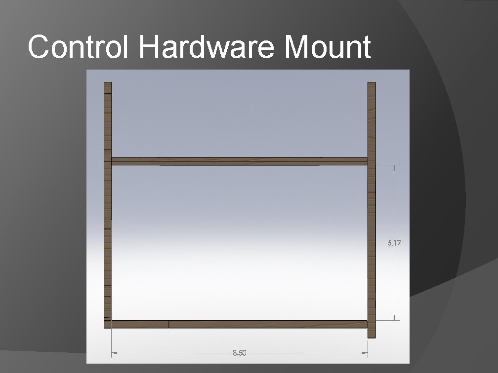
Control Hardware Mount
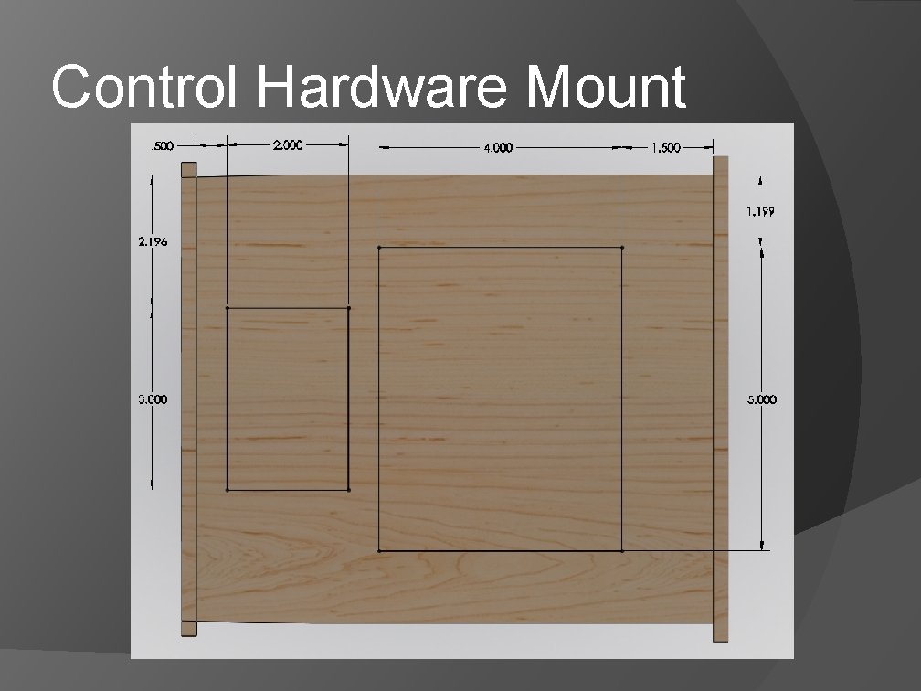
Control Hardware Mount
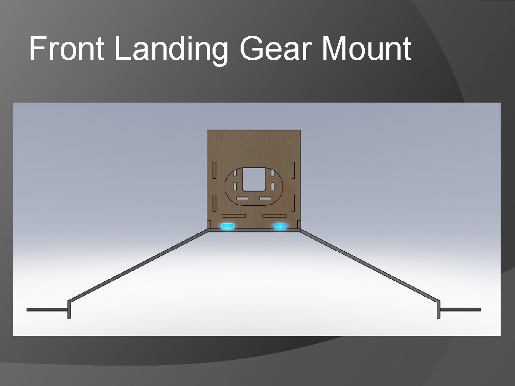
Front Landing Gear Mount
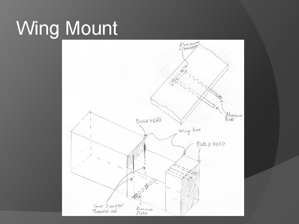
Wing Mount
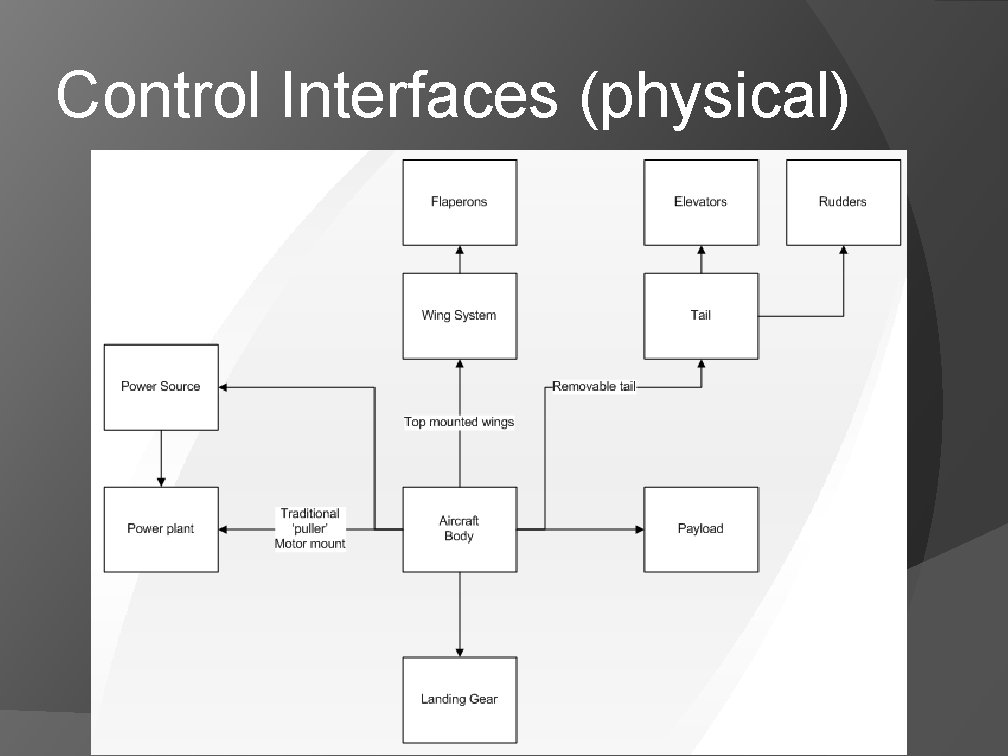
Control Interfaces (physical)
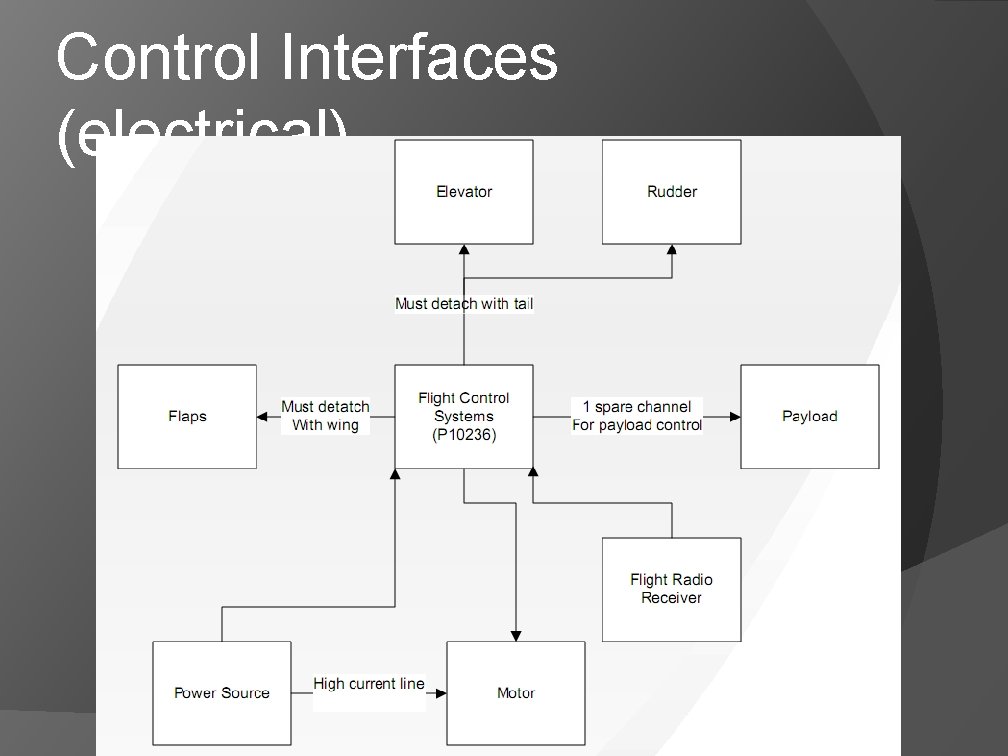
Control Interfaces (electrical)
DETAILED DESIGN REVIEW P 10232 – UAV AIRFRAME C Daniel Graves – James Reepmeyer – Brian Smaszcz – Alex Funiciello – Michael Hardbarger – Project Lead Engineer Airframe Design Airfoil Design Control Systems