
Design of Wind Turbines P M V Subbarao

Design of Wind Turbines P M V Subbarao Professor Mechanical Engineering Department Selection of Optimal Geometrical & Kinematic Variables ….
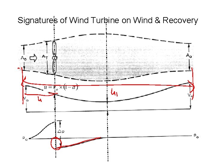
Signatures of Wind Turbine on Wind & Recovery
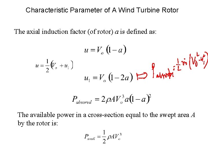
Characteristic Parameter of A Wind Turbine Rotor The axial induction factor (of rotor) a is defined as: The available power in a cross-section equal to the swept area A by the rotor is:
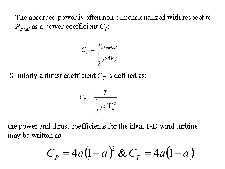
The absorbed power is often non-dimensionalized with respect to Pavail as a power coefficient CP: Similarly a thrust coefficient CT is defined as: the power and thrust coefficients for the ideal 1 -D wind turbine may be written as:
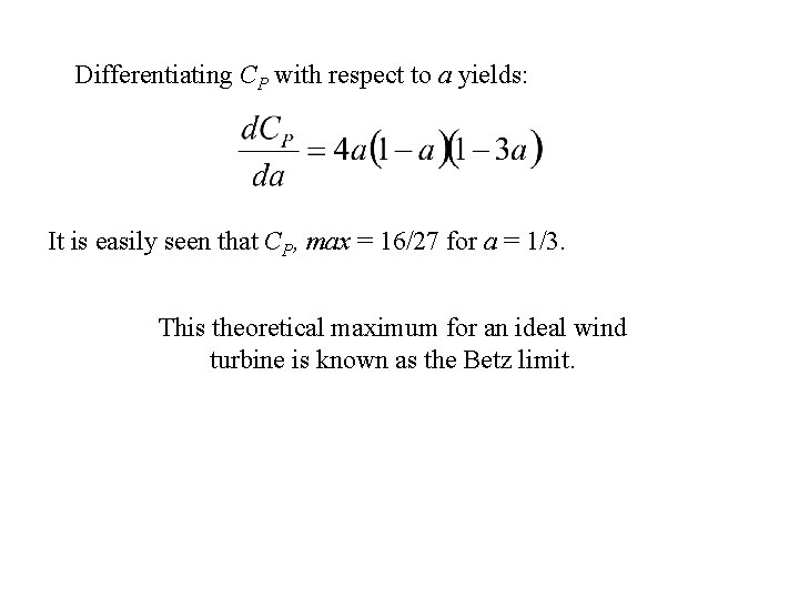
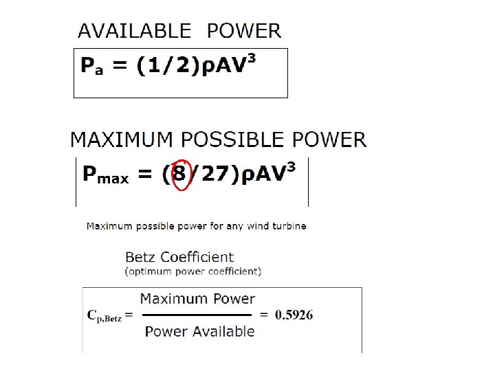
Differentiating CP with respect to a yields: It is easily seen that CP, max = 16/27 for a = 1/3. This theoretical maximum for an ideal wind turbine is known as the Betz limit.
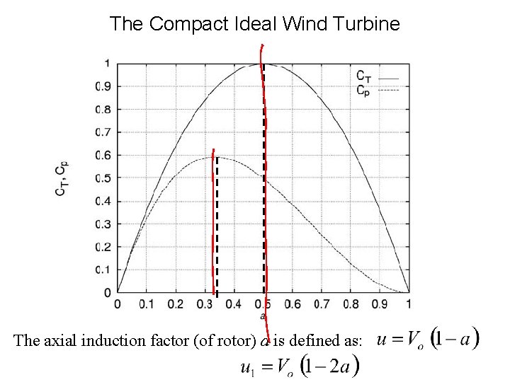
The Compact Ideal Wind Turbine The axial induction factor (of rotor) a is defined as:
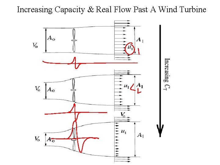
Increasing Capacity & Real Flow Past A Wind Turbine
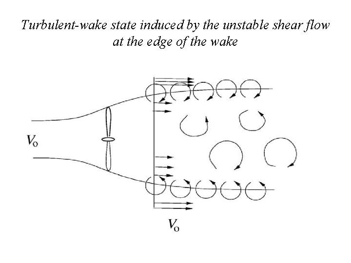
Turbulent-wake state induced by the unstable shear flow at the edge of the wake
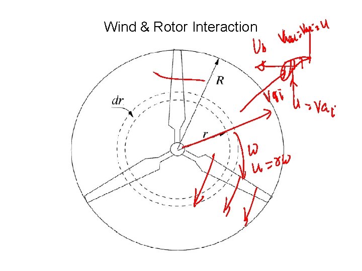
Wind & Rotor Interaction
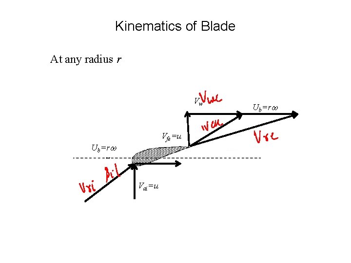
Kinematics of Blade At any radius r Vw Vfe=u Ub=rw Vai=u Ub=rw
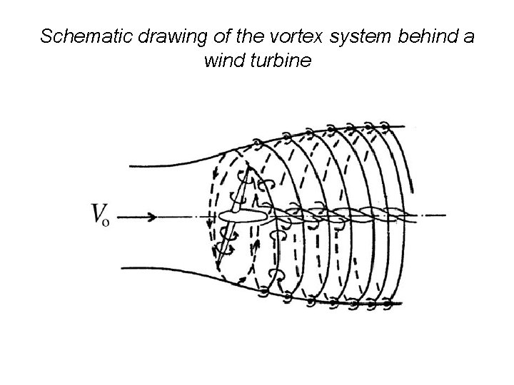
Schematic drawing of the vortex system behind a wind turbine
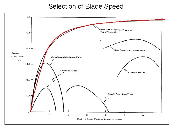
Selection of Blade Speed
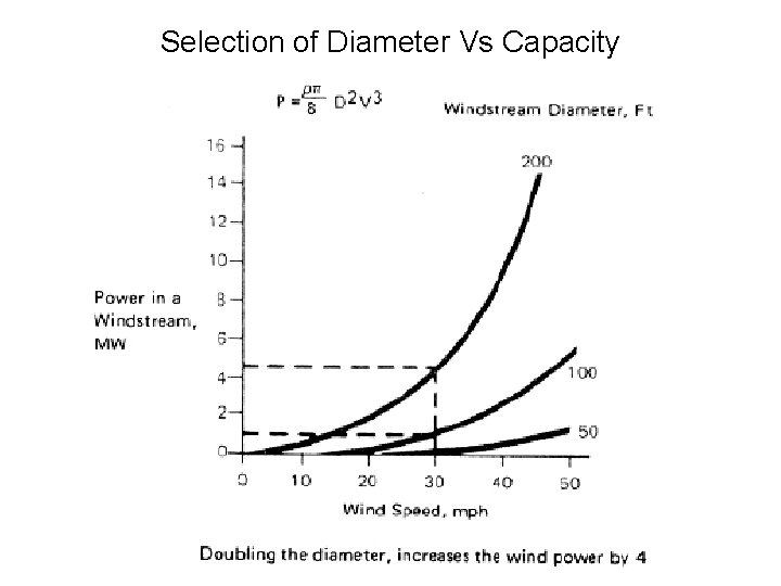
Selection of Diameter Vs Capacity
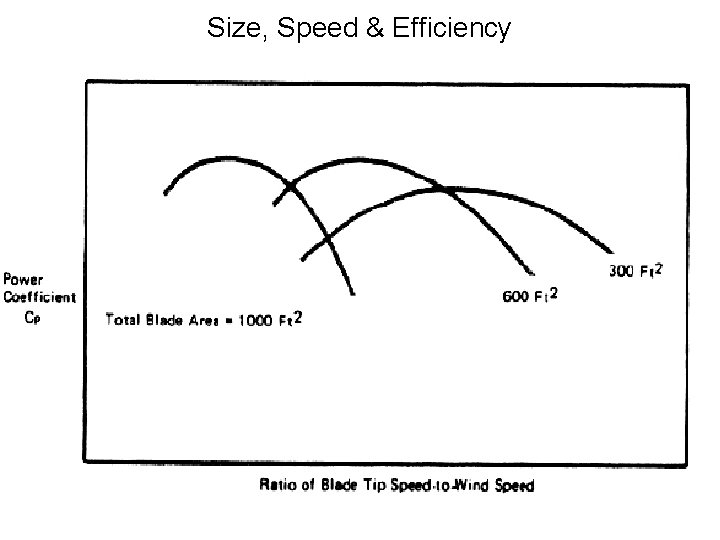
Size, Speed & Efficiency
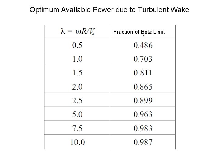
Optimum Available Power due to Turbulent Wake Fraction of Betz Limit
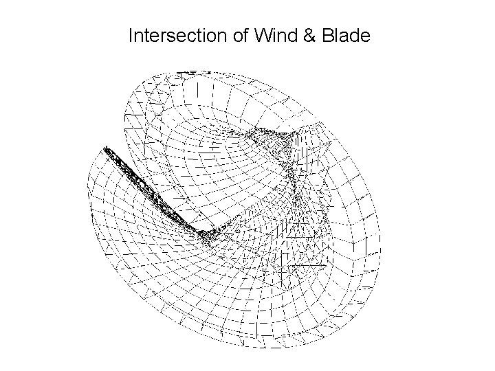
Intersection of Wind & Blade
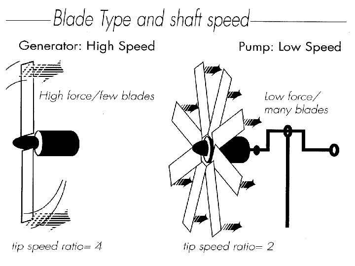
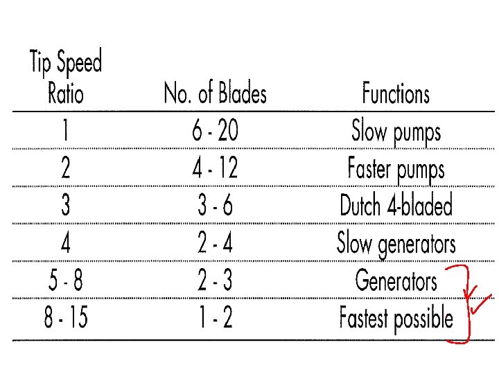
Capacity Vs Number of Blades • For a given efficiency , a wind turbine with large capacity will run at lower speed. • What is the lowest RPM (Revolution Per Minute) a single bladed turbine can make without loosing its efficiency drastically? • It is 60 RPM or one revolution per second. Why? • Because it should sweep whole rotor area in one second. • If turbine rotates slower than this, it will miss some air particles and it's output power will be low. • However if it rotates faster than one revolution per second it will produce more power which is better. • But faster rotating blades create more stresses on overall structure. • Therefore one bladed turbine should run at highest possible safe rpm.
Low Speed for Higher Number of Blades • A two bladed turbine can run at lower speed with high efficiency. • This is because while one blade sweeping one half of the circle area, the other blade is sweeping the other half. • By using same analogy a three bladed turbine can run much lower speeds with high efficiency. • Low speed turbine increase the cost of electrical equipment. • Higher number of large blades will increase wind turbine and civil structure costs. • A techno-economically viable option is essential.
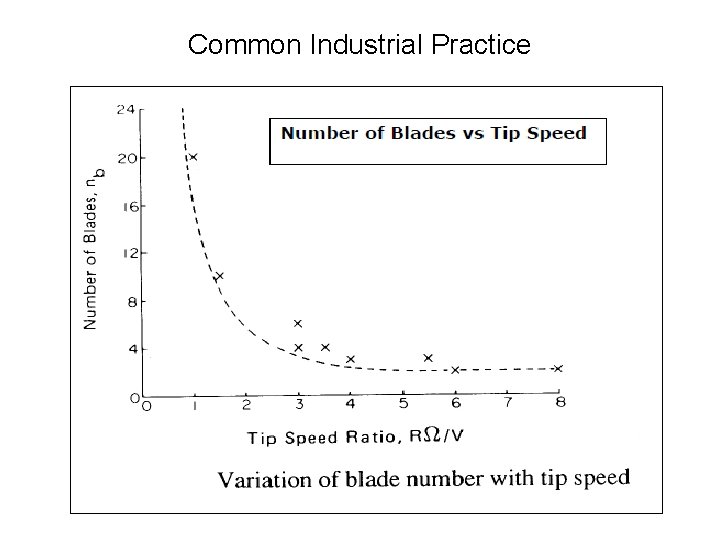
Common Industrial Practice
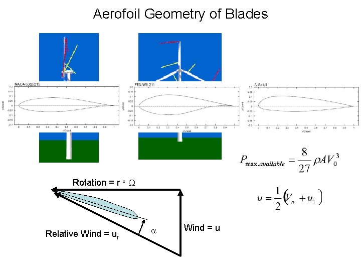
Aerofoil Geometry of Blades Rotation = r * W Relative Wind = ur a Wind = u
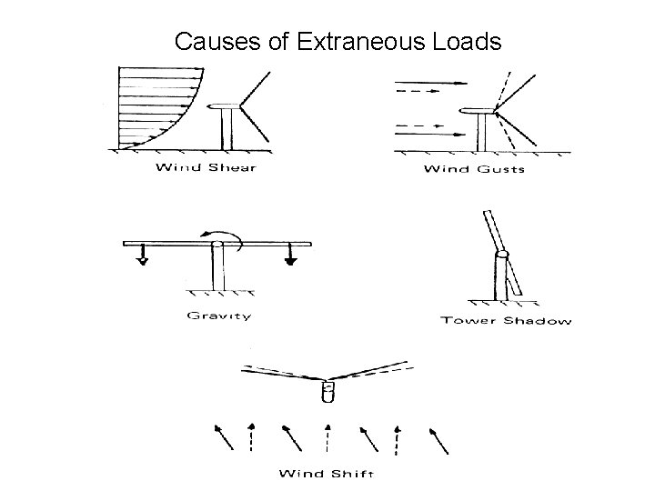
Causes of Extraneous Loads
Wind Turbine Field Performance • Issues effecting wind turbine performance – Blade Design • Efficiency of large turbine blades are close to the aerodynamic optimum for steady uniform winds. • Unsteady and non-uniform wind conditions cause: – Blade section stall. – Degradation of Wind Turbine performance. – Noise issues with the local community • Wind turbine noise increases due to: – Unsteady in-flow conditions. – Flow interaction from support structure or wakes from other wind turbines.
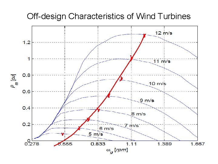
Off-design Characteristics of Wind Turbines
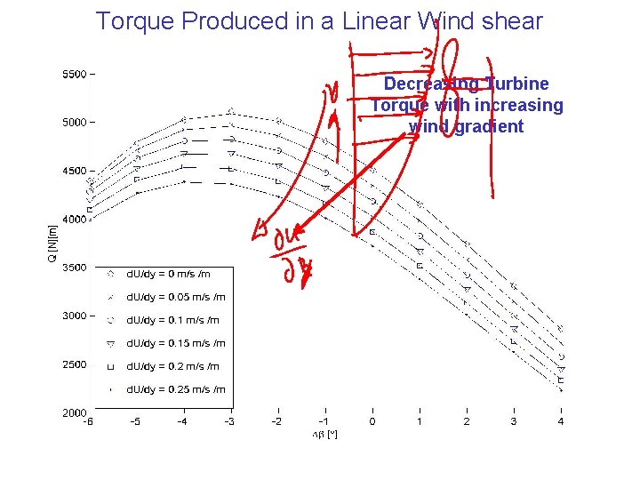
Torque Produced in a Linear Wind shear Decreasing Turbine Torque with increasing wind gradient
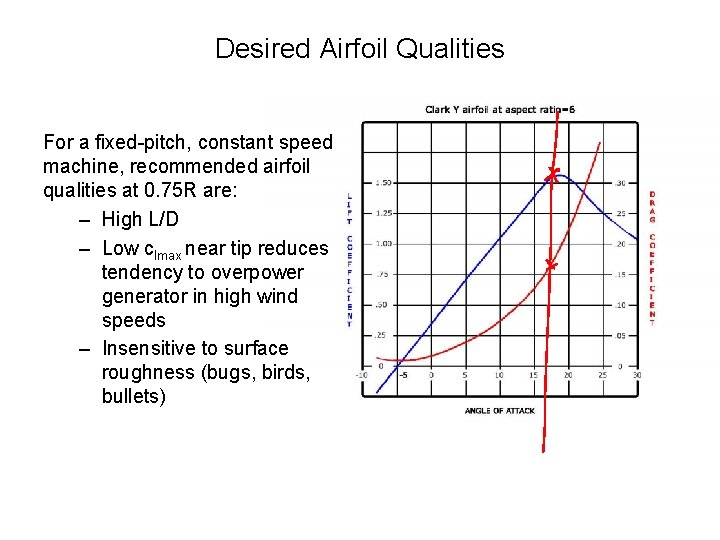
Desired Airfoil Qualities For a fixed-pitch, constant speed machine, recommended airfoil qualities at 0. 75 R are: – High L/D – Low clmax near tip reduces tendency to overpower generator in high wind speeds – Insensitive to surface roughness (bugs, birds, bullets)
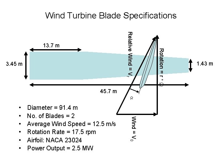
Wind Turbine Blade Specifications 3. 45 m 45. 7 m a Diameter = 91. 4 m No. of Blades = 2 Average Wind Speed = 12. 5 m/s Rotation Rate = 17. 5 rpm Airfoil: NACA 23024 Power Output = 2. 5 MW Wind = V 0 • • • Rotation = r * W Relative Wind = Vr 13. 7 m 1. 43 m
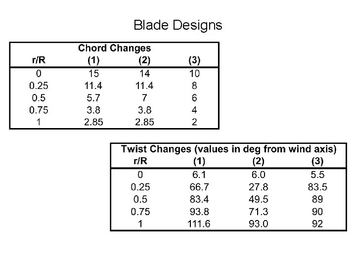
Blade Designs
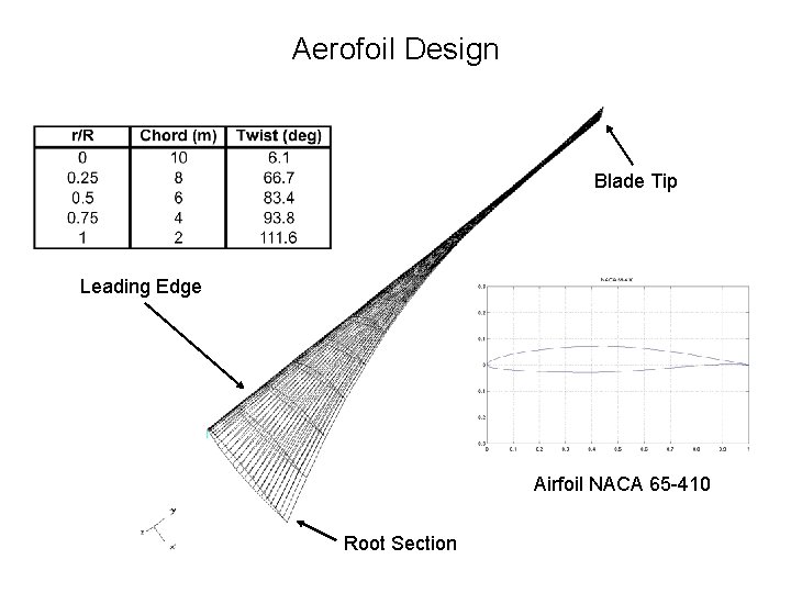
Aerofoil Design Blade Tip Leading Edge Airfoil NACA 65 -410 Root Section
- Slides: 32