Design of the Assembly Stand Chendi Shen 1232015

Design of the Assembly Stand Chendi Shen 12/3/2015 Tsinghua U.

Bottom of the assembly stand with predrilled holes

3 posts for positioning 三个定位柱

A bottom piece for supporting the plates

First, place the bottom endplate, then start stacking the plates. On the six sides of the endplate, some sides have 3 holes and some have 4. This is to avoid conflicting with the WLS fiber holes and still make the holes equal-spacing on each side. Six 2. 5 -mm dia aluminum posts are inserted through pre-drilled holes of the bottom assembly stand all plates.

Continue stacking all plates. The six poles can be raised to align all plates.

All 194 x lead, 194 x scintillator, and 388 x paper layers are stacked

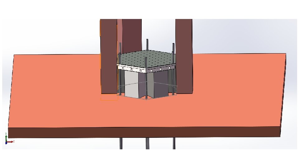
Add the top end-plate which is identical to the bottom endplate.
, and a top plate for compressing all layers.")
Now add two supporting posts (white), and a top plate for compressing all layers. Pressure sensors will be plated between the horizontal compression bar and the top endplate. Chendi reported that the compression is determined by the height of the two white posts, but this would not work. Jianping and Xiaochao commented that each module can be different and we should make the posts a little shorter and use the pressure sensors alone to continuous monitor/adjust the compression.

Then, compression bar, compression posts and positioning posts are removed, nuts added to the six Al rods, and the whole module wrapped by black tape. ― but this would not work because the layers will “spring back' as soon as the compression is removed. Need to move the compression posts (previous slide) away from the module sides, and wrap tapes around with the compression in place.

And side plates attached ― Same as last slide, need compression in place for this step. ― There is also the question of whether we should have pre-drilled holes on the side plates, etc.
- Slides: 12