Design of Rockery Retaining Walls Prepared by Hazar

Design of Rockery Retaining Walls Prepared by: Hazar kharoof Jihad jaradat Tamara daik Bissan jamal salah Supervisor: Dr. Isam Jardaneh

As we know : A rockery retaining wall is a retaining or protection structure that consists of stacked rocks without mortar, concrete, or steel reinforcement.

So we can say that we use of rows of big rocks to build walls is one the earliest construction methods used by man. The design method was based on experience and trial and error. No specific construction or design procedures were available at that time

Local Rockeries : One of the famous use of rockery as retaining wall is in the City of Rawabi. The following pictures show examples of the walls in Rawabi City. It is usually called big boulder retaining walls. This type of wall is new trend of walls. It is mainly use as excavation support system rather than retaining wall.

We Talked about the main methods of design of rockery walls, such as: Gray & Sotir, Herndon, Hemphill, SAGE. In general, all four methods are based on the assumption that the retained soil exerts a lateral earth pressure on the back of the rockery and that the rockery must resist this pressure though rock interaction, rockery weight, and rockery size. In that respect, the methods are almost similar and, as a result, the computed base widths are similar.

ROCKERY CONSTRUCTION GUIDELINES: The guidelines considered here are including but not limited to the following: • stability analysis • The soil behind the stone boulder retaining wall (crushed rock zone and backfill soil) • And drainage requirements for subsurface and surface drainage.

Important note : Six most commons causes of stone boulder walls failure were observed as follows : 1. Little or no drainage was provided 2. The backfill was of poor quality or poorly placed and compacted 3. Rockery face was constructed too steep or too high 4. The rockery was constructed over a poor foundation 5. The rockery was constructed of unsound rock 6. The overall workmanship of the constructed product was poor

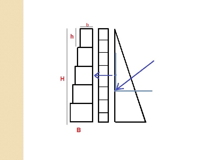
RECOMMENDED DESIGN METHOD STATIC DESIGN Design of any retaining structure involves the determination of two categories of forces: driving forces and resisting forces. Design parameters: • ɸ: friction angle • Δ: interface friction angle. • Ψ: allowable back cut angle. • γs: Soil unit weight (between 17. 2 -20. 4 KN/m³). • γr: rock unit weight (assumed 23. 5 KN/m³ ). • Q: allowable bearing pressure. • Qs: surcharge load.

ØLateral earth pressure: The earth pressure is typically computed by multiplying the lateral earth pressure coefficient for active soil conditions (KA) by the unit weight of the soil (γs), are two potential sources of lateral earth pressure acting on the back of the rockery- that exerted by retained soil, and that exerted by the crushed rock back drain. Generally the pressure exerted by the crushed rock back drain is less than that exerted by the retained soil, for three reason: • The friction angle of the crushed rock (ɸ CR) is generally much higher than the soil This will result in smaller value of (Ka). • The crushed rock has a lower unit weight than the retained soil due to the increased void space • The crushed rock layer is generally relatively narrow, on the order of 300 mm (12 in) thick. As a result, the active failure wedge typically extends through the crushed rock and in to the retained soil behind the crushed rock

The coulomb method, which accounts for frictional interaction between the retained soil and the retaining structure, is the recommended method for determination of KA. Here the equation:

Sliding �

Sliding resistance: �Rockeries generally resist sliding primarily through friction along the bottom of the base rock, which is a function of the normal force acting on the base of the rockery and the coefficient of sliding between the base rock and foundation soil. The normal force consists of the vertical component of the Coulomb active earth pressure (FA, V) acting downward) and the weight of the rockery. �The weight of the rockery can be estimated by assuming certain minimum dimensions for the rockery
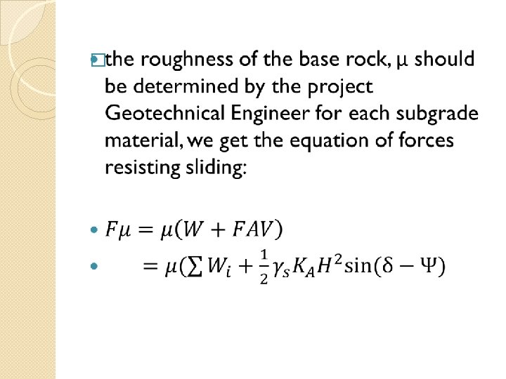

Factor off safety for sliding: �

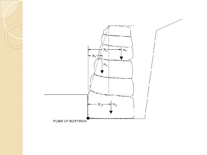
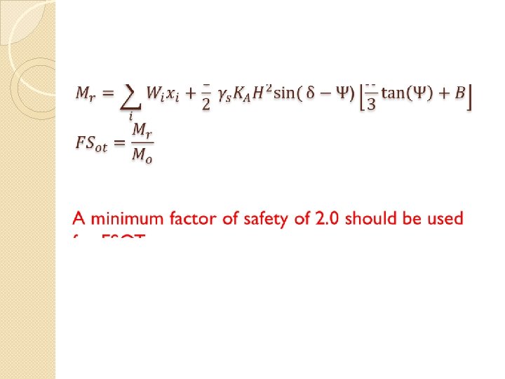
ØOverturning the forces acting horizontally behind the rockery will also tend to cause it to tip forward about its toe. These forces include the horizontal component of the lateral earth pressure (FA, H) and the additional horizontal pressure to a vertical surface surcharge (FS). The overturning moments caused by these forces are counter balanced by resisting moments due to the weight of the rockery (W), the vertical component of the lateral earth pressure (FA, V), The overturning and resisting moments are computed by summing moments about the toe of the rockery.

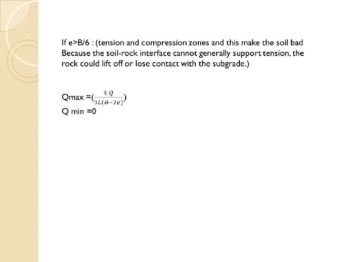
ØBearing Capacity

First case solution : Soil type : silty clay. ϒsoil =18 ϒ rock =23 ɸ=18
 * ɸ = 12. 1° =0. 473")
�by using equation : �δ=( �Ka 2/3) * ɸ = 12. 1° =0. 473

Sliding : ᶲ Ψ Ɣs KA Qs H δ FA, H FS FD 0. 314 0 18 0. 473692 0 1. 5 0. 209333 9. 382856 0. 314 0 18 0. 473692 0 3 0. 209333 37. 53142 0. 314 0 18 0. 473692 0 4. 5 0. 209333 84. 4457 0. 314 0 18 0. 473692 0 6 0. 209333 150. 1257 0 234. 5714 0 18 0. 473692 0 7. 5 0. 209333 234. 5714 For first row: FD=. 5*18*(1. 5²)*0. 473*cos 12. 1° +0 = 9. 38 0. 314

Friction : B H Wi ∑Wi ϻ ɣr KA 1. 2 1. 5 41. 4 0. 6 23 1. 4 1. 5 48. 3 89. 7 0. 6 1. 5 55. 2 144. 9 1. 8 1. 5 62. 1 2 1. 5 69 Δ Ψ Ha FA, v Wi+F FR 0. 473692 0. 209333 0 1. 5 1. 993346 43. 39335 26. 03601 23 0. 473692 0. 209333 0 3 7. 973385 97. 67339 58. 60403 0. 6 23 0. 473692 0. 209333 0 4. 5 17. 94012 162. 8401 97. 70407 207 0. 6 23 0. 473692 0. 209333 0 6 31. 89354 238. 8935 143. 3361 276 0. 6 23 0. 473692 0. 209333 0 7. 5 49. 83366 325. 8337 195. 5002 For first row: FR=(1. 2*1. 5*23*1 +0. 5*18*(1. 5²)*0. 473*sin 12. 1° )*0. 6=26. 03

FSsl : FR FD FSSL 26. 03601 9. 382856 2. 774849 58. 60403 37. 53142 1. 561466 97. 70407 84. 4457 1. 157005 143. 3361 150. 1257 0. 954774 195. 5002 234. 5714 0. 833436 For first row: FSSL=26. 03/9. 38 =2. 77

Overturning : ɣs KA H Δ Ψ Qs MD 18 0. 473692 1. 5 0. 209333 0 10 10. 02046 18 0. 473692 3 0. 209333 0 10 58. 84755 18 0. 473692 4. 5 0. 209333 0 10 174. 6298 18 0. 473692 6 0. 209333 0 10 385. 5159 18 0. 473692 7. 5 0. 209333 0 10 719. 6543 For first row: MD=0. 5*18*(1. 5²)*0. 473 cos 12. 1° *(1. 5/3) +0 =9. 3

ɣs KA H Δ Ψ B Wi Xi ∑Wi*Xi FA, v MR 18 0 1. 5 0. 209333 0 1. 2 41. 4 0. 6 24. 84 3. 986693 28. 82669 18 0 3 0. 209333 0 1. 4 48. 3 0. 7 66. 93 15. 94677 82. 87677 18 0 4. 5 0. 209333 0 1. 6 55. 2 0. 8 129. 03 35. 88023 164. 9102 18 0 6 0. 209333 0 1. 8 62. 1 0. 9 213. 9 63. 78708 277. 6871 18 0 7. 5 0. 209333 0 2 69 1 324. 3 99. 66731 423. 9673 For first row: MR =0. 5*18*(1. 5²)*0. 473 cos 12. 1° *(1. 2)+41. 4*(1. 5/2) =28. 8

FSOT : Mo MR FSOT 10. 02046 28. 82669 2. 876783 58. 84755 82. 87677 1. 40833 174. 6298 164. 9102 0. 944342 385. 5159 277. 6871 0. 7203 719. 6543 423. 9673 0. 589126 For first row: FSOT=28. 8/10. 02 =2. 87

Bearing capacity : B Mo MR ∑Wi Fv E B/6 e<B/6? e=B/6 e>B/6 1. 2 10. 0204 28. 8266 41. 4 1. 993346 0. 16661 0. 2 TRUE FALSE 1. 4 58. 8475 82. 8767 89. 7 7. 973385 0. 453984 0. 233333 FALSE TRUE 1. 6 174. 629 164. 910 144. 9 17. 94012 0. 859688 0. 266667 FALSE TRUE 1. 8 385. 515 277. 687 207 31. 89354 1. 351368 0. 3 FALSE TRUE 2 719. 654 423. 967 276 49. 83366 1. 907478 0. 333333 FALSE TRUE For first row : E=1. 2/2 –((28. 8 -10. 02)/1. 99) =0. 166 B/6 =0. 2 So e< B/6 Qmax= (1. 99/1. 2)*(1+6*(0. 166/1. 2)) =66. 2 Qmin = (1. 99/1. 2)*(1+6*(0. 166/1. 2)) = 0. 277

e<B/6 Q max Qmin e=B/6 Qmax e>B/6 Qmin q Qmax Qmin 66. 28518 0. 277322 66. 28518 0 150 173. 355911 0 205. 508 -5. 38571 205. 508 0 150 98. 40641672 0 429. 8806 -24. 9349 429. 8806 0 150 -23. 8752128 0 730. 5575 -62. 096 730. 5575 0 150 -180. 5470519 0 1095. 198 -117. 668 1095. 198 0 150 -362. 9913066 0

STUDY CASES Now we have to analysis of several suggested real cases for rockery retaining wall. It includes cases for : ØTemporary Rocky Retaining Wall (Two systems were used for this case, for to support silty clay and the second to support marl soil. ) ØPermanent Retaining Wall (This section represents analysis and design of rockery retaining wall as permanent retaining wall. In this case, selected backfill is used as backfill soil. The construction of this wall should be according to the recommended construction method regarding backfill soil, drainage, selected fill, etc.

Temporary rockery

ØTemporary Rocky Retaining Wall silty clay marl soil γ =18 k. N/m 3 Unit weight of the rockery = 23 k. N/m 3 (including voids) Angle of internal friction =18° Angle of internal friction =23° cohesion = 0 k. N/m 2 to be in the safe side. qs= 0 k. N/m 2 Ψ= 0º qall =120 k. N/m 2 qall = 200 k. N/m 2 Sliding factor of safety = 1. 1 -1. 3 Overturning factor of safety = 1. 3 -1. 5 Bearing pressure should be not more that the of the qall foundation soil.

ØPermanent Retaining Wall backfill soil and foundation soil γ =18 k. N/m 3 Unit weight of the rockery = 23 k. N/m 3 (including voids) Angle of internal friction =30° of selected fill. qs= 10 k. N/m 2 Ψ= 0º qall = 200 k. N/m 2 Sliding factor of safety = 1. 5 Overturning factor of safety = 2. 0 Bearing pressure should be not more that the allowable bearing capacity of the foundation soil.

Example of some output results for temporary rockery retaining: Case H number B FSsl FS ot pressure Safe/not Marl soil 7. 5 2 1. 4 1. 17 191 Not safe It is clear that when using rockery retaining wall as a temporary retaining wall, the factor of safeties are less than the recommended for general retaining walls. In this case, when constructing rockery retaining walls as temporary structure precautions should be considered and the permanent retaining wall should be constructed as soon as possible:

Example of some output results for permanent rockery retaining: The construction of this wall should be according to the recommended construction method as presented in chapter four regarding backfill soil, drainage, selected fill, etc. The following examples show the output results for different heights using same backfill soil and same foundation soil Case number H B FSsl FS ot pressure Safe/no t 3 5 2. 03 2. 83 172 Safe 4 6 3 2. 16 2. 99 210 Not safe

Properties of making permanent rockery wall: �Effective world wide system. �Used locally in Rawabi city with height of about 5 Km. �Low cost compared with reinforced wall. �It gives beautiful view.

Properties of making temporary rockery wall: �Support excavation and reduce the expected problem. �safe, no riskiness during installation by cranes. �Quickly solution, no time for curing or pour concrete. �Available locally.

Other support system �These systems are expensive and locally unavailable: �Freezing �Sheet piling �Soil nailing

Thank you
- Slides: 40