DESIGN OF OPEN WEB GIRDER BRIDGE ATUL KUMAR

DESIGN OF OPEN WEB GIRDER BRIDGE ATUL KUMAR VERMA XEN/SB-I/RDSO

INTRODUCTION ØTruss bridge: § Used for spans greater than what can be spanned economically by a plate girder bridge. § In general truss bridges are used for spans greater than 30 m.

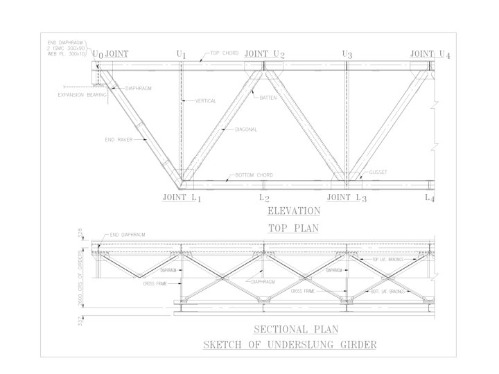
INTRODUCTION Ø Forms Of Open Web Girder Bridges § Through Type § Deck Type (Underslung) § Semi Through Type (Cont. . . )
 § Rail")
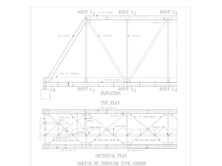
COMPONENTS OF THROUGH TYPE BRIDGE Ø Floor System: § Cross girder (Bending) § Rail bearers or Stringers(Bending) Ø Primary Members: § § § Bottom chord members (Tension members) Top chord members (Compression members) End rackers (Compression & Bending members) Diagonals (Reversible stress members) Verticals (Tension members & redundant members)
 Ø Secondary members: § § § Bottom lateral bracings")
COMPONENTS (Cont. . . ) Ø Secondary members: § § § Bottom lateral bracings (Axial force) Top lateral bracings (Axial force) Sway bracings & knee sway (Axial force & Bending) Portal bracings & knee portal (Axial force & Bending) Main gussets Bearings

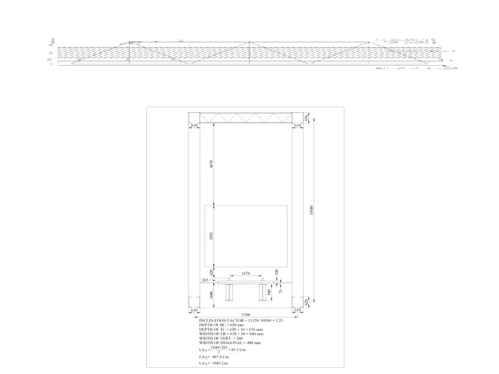
GENERAL CONFIGRUATION Ø Type of truss § Warren truss with verticals for standard railway spans § Other forms may be adopted as per different conditions Ø Number of panels § Weight of truss Vs Floor system § Optimum number is 6 to 10 Ø Length of panel § Weight of truss Vs Floor system § Optimum length is 6 m. to 9 m. Ø Inclination of diagonals § Between 45° and 60° with the horizontal
 Ø Height of truss § Through type Vs Deck type §")
GENERAL CONFIGRUATION (Cont…) Ø Height of truss § Through type Vs Deck type § Between 1/8 and 1/5 of span length Ø Spacing of trusses § Sufficient to prevent overturning due to lateral loads § > 1/3 of height of truss & > 1/20 of span

ESTIMATION OF LOADS Ø Dead load Ø Live load Ø Dynamic effects Ø Longitudinal force Ø Racking force Ø Wind pressure effect Ø Forces and effect due to earthquake

DEAD LOAD Ø Dead load of truss is assumed before design on the basis of experience & earlier designs Ø After design of truss the actual dead load of truss is compare with assumed dead load Ø If there is difference between two, then assumed dead load is revised and structure is designed with revised dead load

LIVE LOAD Ø Clause 2. 3 of bridge rule. Ø Estimated on the basis of loading standard. Ø EUDL(equivalent uniformly distributed loads ) are given in appendix of bridge rules for different loading standards. Ø EUDL is given for bending moment and shear force Ø EUDL for Bending Moment: § For Maximum forces in elements resisting bending (Bottom chords & top chords) Ø EUDL for Shear Force: § For Maximum forces in elements resisting shear at section (end racker, diagonals, verticals)

DYNAMIC EFFECTS Ø Clause 2. 4 of bridge rule Ø Augmentation in load due to dynamic effects is considered by adding a load equivalent to a coefficient of dynamic augment(CDA) multiplied by the live load giving the maximum stress in member under consideration. Ø For single track spans: § CDA=0. 15+(8/(6+L)) subject to a maximum of 1. 0 Where L= loaded length of span in meters for the position of the train giving the maximum stress in the member under consideration

LONGITUDINAL FORCES Ø Clause 2. 8 of bridge rule Ø Value of longitudinal force due to either tractive effort or braking force shall be obtained from appendices. Ø Values depend on loaded length and standard of loading. Ø Maximum of tractive effort or braking force is taken as longitudinal force.

RACKING FORCE Ø Clause 2. 9 of bridge rule. Ø Lateral bracings of loaded deck of spans to be designed for a lateral load due to racking force of 600 kg/m. treated as moving load. Ø Racking force not to be considered for calculating stresses in chords or flanges of main girders.

WIND PRESSURE EFFECT Ø Clause 2. 11 of bridge rules. Ø Wind pressure expressed as a equivalent static pressure in windward direction Ø Wind pressure shall apply to all loaded or unloaded bridges. Ø But bridge shall not considered to carry any live load when wind pressure at deck level exceeds 150 kg/m 2 for B. G. Ø Wind force calculated for loaded spans with wind pressure 150 kg/m 2.
 Ø Wind Force = wind pressure*exposed area Ø Exposed area")
WIND PRESSURE EFFECT (Cont…) Ø Wind Force = wind pressure*exposed area Ø Exposed area = area of moving load + exposed area of truss members. Ø Full area of truss members on windward side +50% area of truss members on Leeward side.

SEISMIC FORCE Ø Clause 2. 12 of bridge rule Ø Seismic forces: § Horizontal seismic force § Vertical seismic force Ø Seismic forces calculated taking into consideration seismic zone, importance of structure and its soil foundation system. Ø Design seismic coefficients: α =βIα α = α /2 h v 0 h
 Ø F=Wm*αh (or αv) F = Seismic force Wm=Weight of mass")
SEISMIC FORCE (Cont…) Ø F=Wm*αh (or αv) F = Seismic force Wm=Weight of mass under consideration ignoring reduction due to buoyancy Ø Horizontal seismic force due to live load on the bridge shall be ignored when acting in the direction of traffic Ø When acting in the direction perpendicular to traffic, this is to be considered for 50% of design live load without impact.

ANALYSIS OF FORCES Ø To find out the forces in members of truss due to various loads. Ø Forces can be found out either by suitable computer program or by hand calculation. Ø Hand calculation is done by using influence line diagrams(ILD) for various members of truss. Ø ILD are prepared for a member of truss by calculating force in member as a unit load moves across the deck of the truss. Ø Area of ILD calculated and multiplied by the force intensity to get force in a particular member.

DEAD LOAD ANALYSIS Ø Dead load intensity is same for all the members of truss. Ø Dead load intensity (per truss per unit length) = total assumed dead load/(2*span length) Ø Force due to dead load in each member of truss are calculated by multiplying dead load intensity with area of ILD.

LIVE LOAD ANALYSIS Ø Bottom chord members have tension in ILD. Loaded length is length of span. Ø Top chord members have compression in ILD. Loaded length is length of span. Ø Live load intensity for chord members =EUDL bending/(2*loaded length) Ø CDA for chord members is calculated taking L as span length. Ø End racker have compression in ILD. Loaded length is length of span. Ø Live load intensity for end racker =EUDL shear/(2*loaded length)
 Ø CDA for end racker is calculated taking L as")
LIVE LOAD ANALYSIS (Cont…) Ø CDA for end racker is calculated taking L as span length. Ø Diagonal members have both tension & compression in ILD. loaded length for tension & compression is found from ILD. Ø Live load intensity & CDA for diagonals are calculated for tension & compression both based on their respective loaded lengths. Ø Force due to live load = ILD area*live load intensity Ø Force due to dynamic effect = CDA*force due to live load

LONGITUDINAL FORCE Ø Longitudinal force taken for only bottom chord members. Ø This depends on position of different bottom chord members. Ø For bottom chord member in end panel loaded length for longitudinal force is full span. Ø Loaded length reduces by one panel length as we take bottom chords of other panels starting from end to centre. Ø Based on loaded length longitudinal force is found in bottom chord members.

WIND LOAD ANALYSIS Ø General concept of load transfer and how the wind forces are distributed among the members ØWind Load = Wind pressure X exposed area ØExposed Area = Area of moving load + exposed area of truss member
 ØThrough Type Truss EXPOSED AREA TC BC 1. Between RL")
WIND LOAD ANALYSIS (Cont…) ØThrough Type Truss EXPOSED AREA TC BC 1. Between RL and bottom of B. C. B 1 2. B 2 3. Between Moving load and RL of stringer ER, Vertical , Diagonal (l x b x No. ) Moving load 4. TC and top of moving load T 1 5. Top Chord T 2 6. Gusset Top T 2 B 3 Total AT=T 1+T 2+T 3 AB=B 1+B 2+B 3
 Ø Wind force on top chord = Wind pressurex. ATX")
WIND LOAD ANALYSIS (Cont…) Ø Wind force on top chord = Wind pressurex. ATX 1. 5=WT Ø Wind force on bottom chord= W P[1. 5(ABB 3)+B 3]=WB Ø Nodal force at top chord: § At intermediate nodes = WT/No. of top panel=Tint. § At end nodes = Tint/2 Ø Nodal force at bottom chord: § At intermediate nodes = WB/No. of bottom panel=Bint. § At end nodes = Bint/2
 Ø Wind load analysis is done for following situations: §")
WIND LOAD ANALYSIS (Cont…) Ø Wind load analysis is done for following situations: § Horizontal bending of bottom chord due to wind force on bottom chord & moving load § Vertical bending of span due to wind force on bottom chord & moving load § Horizontal bending of bottom chord due to wind force on top chord transmitted through sway bracings § Vertical bending of span due to wind force on top chord transmitted through sway bracings § Horizontal bending of top chord due to wind load on top chord § Overturning effect of portal

SEISMIC FORCE ANALYSIS Ø Seismic force calculated in horizontal & vertical direction Ø In horizontal direction seismic force calculated for bottom chord & top chord Ø On bottom chord seismic force is due to dead load as well as live load & on top chord seismic force is due to dead load only Ø In vertical direction seismic force is due to dead load as well as live load Ø Analysis of seismic forces in members is same as that of wind force

FORCE IN TRUSS MEMBERS Ø Force in truss members found by adding forces due to dead load, live load with dynamic effect, longitudinal loads, wind load or seismic loads

DESIGN OF STRINGER Ø Loaded length for stringer = length of one panel Ø Bending moment & shear force calculated by getting EUDL bending or EUDL shear as per case Ø Dead load of stringer & track also considered Ø Section assumed for stringer Ø Actual stresses calculated for bending moment & shear force Ø Permissible stresses for bending is minimum of : § Basic permissible stress (clause 3. 7 of SBC) § Permissible stress in fatigue (clause 3. 6 of SBC) § Permissible stress in bending compression (clause 3. 9 of SBC)
 Ø Permissible shear stress (Table II of SBC) Ø Actual")
DESIGN OF STRINGER (Cont…) Ø Permissible shear stress (Table II of SBC) Ø Actual stress < permissible stress then assumed section is safe otherwise revise the section Ø Design of connection between web & flange of stringer: § Calculation of horizontal shear at the level of weld § Permissible stress in weld (Appendix-G of SBC & clause 13. 4 of welded bridge code) § Size of weld calculated (Subject to clause 6. 2 of welded bridge code)
 Ø Provision of stiffeners (Clause 5. 10 of SBC) Ø")
DESIGN OF STRINGER (Cont…) Ø Provision of stiffeners (Clause 5. 10 of SBC) Ø Design of stringer bracings: § Calculation of lateral load (Clause 2. 9. 2 of bridge rule) § Analysis force in stringer bracings. § Design of stringer bracings (Clause 6. 2. 3 & 3. 8 of SBC)

DESIGN OF CROSS GIRDER Ø Loaded length for cross girder for EUDL = 2*centre to centre distance of cross girder Ø L for CDA = 2. 5*cross girder spacing Ø Bending moment & shear force calculated by getting EUDL Ø Dead load of stringer, track & cross girder also considered Ø Section assumed for cross girder Ø Design process for cross girder is same as stringer
 Ø Connection of cross girder with stringer § Calculate")
DESIGN OF CROSS GIRDER (Cont…) Ø Connection of cross girder with stringer § Calculate number of rivets for: -one span loaded -both span loaded Ø Connection of cross girder with vertical & Bottom chord § Find rivet value & calculate number of rivets required for connection

DESIGN OF BOTTOM CHORD Ø Bottom chord members are tension member Ø Section assumed for Bottom chord members (Taking into consideration clause 4. 5 & clause 6. 7 of SBC) Ø Effective area of the section calculated (clause 4. 3. 2 of SBC) Ø Actual stresses calculated for axial tension for: § Without longitudinal & seismic or wind forces § With longitudinal & seismic or wind forces Ø Permissible stress for axial tension is minimum of: § Basic permissible stress (clause 3. 7 of SBC) § Permissible stress in fatigue (clause 3. 6 of SBC)
 Ø Permissible stress for wind or seismic case is")
DESIGN OF BOTTOM CHORD (Cont…) Ø Permissible stress for wind or seismic case is increased by 16. 667% (Table 1 of SBC ) Ø Actual stress < permissible stress for both cases then assumed section is safe otherwise revise the section Ø Design of stitching weld: § Calculation of force at the level of weld § Permissible stress in weld ( appendix-G of SBC & clause 13. 4 of welded bridge code) § Size of weld calculated (subject to clause 6. 2 of welded bridge code) Ø Design of lacing & battening of tension members (Clause 6. 9 & 6. 10 of SBC) Ø Design of diaphragms (Clause 6. 16 of SBC)

DESIGN OF TOP CHORD Ø Top chord members are compression member Ø Section assumed for top chord members (taking into consideration clause 4. 5 & clause 6. 2 of SBC) Ø Effective area of the section (clause 6. 2. 2 of SBC) Ø Actual stresses calculated for axial compression for : § Without seismic or wind forces § With seismic or wind forces Ø Permissible stress in axial compression is minimum of: Ø Basic permissible stress (clause 3. 7 of SBC) Ø Stress in axial compression (clause 3. 7 of SBC) Ø Permissible stress in fatigue (clause 3. 6 of SBC)
 Ø Permissible stress for wind or seismic case is")
DESIGN OF TOP CHORD (Cont…) Ø Permissible stress for wind or seismic case is increased by 16. 667% (Table 1 of SBC ) Ø Actual stress < permissible stress for both cases then assumed section is safe otherwise revise the section Ø Design of stitching weld: § Calculation of force at the level of weld § Permissible stress in weld (Appendix-G of SBC & clause 13. 4 of welded bridge code) § Size of weld calculated (Subject to clause 6. 2 of welded bridge code) Ø Design of lacing & battening of compression members (Clause 6. 5 & 6. 6 of SBC) Ø Design of diaphragms (Clause 6. 16 of SBC)

DESIGN OF END RACKER Ø End racker subjected to axial compression & bending (Clause 6. 19 of SBC) Ø Section assumed for end racker (taking into consideration clause 4. 5 & clause 6. 2 of SBC) Ø Effective area of the section (Clause 6. 2. 2 of SBC) Ø Actual stresses calculated for axial compression & bending for : § Without seismic or wind forces § With seismic or wind forces Ø Permissible stress in compression is minimum of: § Basic permissible stress (Clause 3. 7 of SBC) § stress in axial compression (Clause 3. 7 of SBC) § permissible stress in fatigue (Clause 3. 6 of SBC)
 Ø Permissible stress in bending (Table 2 of SBC)")
DESIGN OF END RACKER (Cont…) Ø Permissible stress in bending (Table 2 of SBC) Ø Permissible stress for wind or seismic case is increased by 16. 667% for axial compression & bending both (Table 1 of SBC ) Ø Adequacy of section is checked for combined stresses for both cases (Clause 3. 11. 1 of SBC ) Ø Design of stitching weld, design of lacing & battening and design of diaphragms same as compression member

DESIGN OF DIAGONALS & VERTICALS Ø Diagonals are reversible stress members Ø Section of diagonals have to be checked for both tension & compression Ø Verticals are tension members Ø Design done similar to bottom chord

DESIGN OF PORTAL BRACINGS SYSTEM Ø Force analysis in members of portal system done forces: (Clause 6. 19 of SBC) § 50% of lateral forces on top chord § Lateral shear equal to 1. 25% of total force in two end racker or in two top chords in end panel whichever is greater Ø Top member of portal subjected to axial compression & bending moment both Ø Design of top member is similar to that of end racker Ø Knee portal is tension or compression member as per the direction of application of nodal force Ø Knee portal is designed for both axial tension & compression

DESIGN OF TOP LATERAL BRACINGS Ø Force analysis in top lateral bracing system done forces: (Clause 6. 17 of SBC) Ø Lateral force on top chord Ø 2. 5% of force in top chord members Ø Bracing members are tension or compression member depending upon the direction of application of nodal force Ø Bracing members are designed for both axial tension & compression

DESIGN OF BOTTOM LATERAL BRACINGS Ø Force analysis in bottom lateral bracing system done forces: (Clause 6. 17 of SBC) § Lateral force on bottom chord & moving load § 50% of lateral force in top chord transmitted through sway bracings § Racking force § Longitudinal force Ø Bracing members are tension or compression member depending upon the direction of application of nodal force Ø Bracing members are designed for both axial tension & compression

DESIGN OF JOINTS Ø Connection at intersection is done as per clause 6. 12 of SBC Ø Rivet value is calculated for rivets to be used Ø Number of rivets = force in member/rivet value Ø Arrangement of rivets at a joint is done as per clause 7. 1 to 7. 9 of SBC Ø Splicing of members is done as per clause 6. 11 of SBC

CAMBER Ø Camber diagram is prepared as per clause 4. 16 & appendix-A of SBC Ø Camber calculated for dead load & full live load including impact Ø Forces in members are calculated for these loads Ø Change in length of members due to forces in members = FL/AE Ø In tension members increase in length & for compression members decrease in length Ø Strain correction is applied in nominal length equal to change in length of members Ø For tension members it is negative & for compression members it is positive
 Ø To avoid changes in the length of floor system further change")
CAMBER (Cont…) Ø To avoid changes in the length of floor system further change in length done in length of all members Ø This change equal to ((loaded chord extension or contraction/loaded chord length)*length of member) Ø For through spans this change is increase in length of members & for deck type it will be decrease Ø Nominal lengths altered as above give a girder correctly stressed camber Ø Nominal lengths and cambered length rounded off to nearest 0. 5 mm.
 Ø Vertical")
DEFLECTION Ø Deflection < length of girder/600 (Clause 4. 17 of SBC) Ø Vertical deflection at the centre of span is calculated by applying unit load at the centre of truss Ø Deflection at centre=∑((FL/AE)*U)

THANK YOU
- Slides: 51