Design of OFFICE OF EXCHANGE Palestinian Post Jericho


 Thickness = 20 cm Dead load =")

 Thickness = 30 cm Dead load =")


 + (0. 12× 0. 24) =0.")
 = 0. 27 Membrane f")


")
")


 Mu-ve = 12. 5")
 Mu-ve = 30. 5")
 Mu-ve = 187.")
 Mu-ve =")

- Slides: 75
Design of OFFICE OF EXCHANGE “Palestinian Post Jericho” Prepared by: Khawla Salameh Noor Barbour Rema’ Alawneh Supervisor: Dr. Riyad Awad
Outlines �Project objective. �Project description. �Preliminary Design of slabs, beams & columns. �Three dimensional structural analysis and design. �Seismic loads analysis.
Project Objective To design the building of Office of Exchange Palestinian Post in Jericho using the primary principles of structures by using one dimensional analysis and three dimensional structural analysis and then design it for seismic loads analysis.
Plan of Ground Floor
Project Description �The building is used for commercial purposes. �The building consists of one floor with an area of 349. 7 m² �The floor assumed to be two blocks, block 1 is used for Customer Services and block 2 for offices. �The elevation of the floor is 7. 05 m in block 1 and 4. 45 m in block 2.
Materials � Reinforced concrete: ◦ Concrete compressive strength fc = 24 MPa for slabs, beams and columns. ◦ Concrete compressive strength fc = 28 MPa for footings. ◦ Modulus of elasticity Ec = 23 GPa � Steel: ◦ Yield stress in steel bars and stirrups = 420 MPa
Design Codes � ACI 318 -08: American concrete institute provisions for reinforced concrete structure design. � UBC-97: Universal Building Code used for seismic loads calculations. � IBC 2009: International Building Code used for live load determination.
Preliminary Design of slabs
Ø One way Solid slab: (Block 1) Thickness = 20 cm Dead load = 5 KN/m² § Live load = 0. 5 KN/m² § Superimposed dead load = 2 KN/m² §
Solid slab reinforcement distribution
Ø One way ribbed slab: (Block 2) Thickness = 30 cm Dead load = 5. 1 KN/m² § Live load = 2. 5 KN/m² § Superimposed dead load = 4. 1 KN/m² §
Superimposed dead load details: Super imposed load = Wtiles + Wmortar + Wsand + Wplaster +0. 104 (partition) = (0. 03)(27) + (0. 03)(23) + (0. 1)(20) + (0. 02)(23) + 0. 104 = 4. 1 KN/m²
Ribbed slab reinforcement distribution
Preliminary Design of beams
Beam distribution in block 1 B 2
q Beams in block 1
Moment diagram for frame 2
Reinforcement distribution for B 1 & B 2: B 1 B 2
Beams details in block 1
q Beams of block 2:
Beams details in block 2
Preliminary Design of columns
Columns distribution: �
Columns details: Column 1 Column 2
Three Dimensional Structural Analysis and Design
Material Property for concrete
Shell Data • Ribbed slab definition
Modification Factors A 1= (0. 06× 0. 52) + (0. 12× 0. 24) =0. 06 m 2 A 2= (0. 06× 0. 52) = 0. 0312 m 2 A 3= (0. 224× 0. 52) = 0. 1165 m 2 I 1= (0. 52× 0. 063/12) + (0. 06× 0. 52) × (0. 08162) + (0. 12× 0. 243/12) + (0. 12× 0. 24) × (0. 06842) =4. 87 e-4 m 4 I 2 = (0. 52× 0. 063/12) = 9. 36 e-4 m 4 I 3 = (0. 52× 0. 2243/12) = 4. 87 e-4 m 4
Modifiers equations Membrane f 11 modifier =(A 2/A 3) = 0. 27 Membrane f 22 modifier = (A 1/A 3)=0. 515 Membrane f 12 modifier = (A 2/A 3) = 0. 27 Bending m 11 modifier = 0. 25×( I 2/ I 3) = 0. 004805 Bending m 22 modifier = 0. 25×( I 1/ I 3) = 0. 25 Bending m 12 modifier = 0. 25×( I 2/ I 3) =0. 004805 Shear v 13 modifier = (A 2/A 3)= 0. 27 Shear v 23 modifier = (A 1/A 3)= 0. 515 Mass m modifier = (M 1 way rib / M solid) = 0. 91 Weight w modifier = (9. 81×M 1 way rib/ 9. 81×M solid)= 0. 91 whe Modifiers for ribbed slab
Modifiers solid slab section data One way solid slab
Modifiers For Beams For columns
Compatibility Check
Check equilibrium Dead load results: Description Block 1 Block 2 645. 66 Slabs 960 Columns 206. 85 112. 5 388. 665 T-section = 375 Beams Total Rec. = 500 2041. 85 1146. 825 Total dead load =3188. 675 KN Total live load= 427. 925 KN Total Superimposed load = 965. 18 KN
Dead, live and superimposed results from SAP Error % in dead load = 4. 4 % < 5% OK Error % in live load = 3 % < 5% OK Error % in superimposed = 2. 25% < 5% OK
Slabs Design
Bending moment for block 1 in y-direction
Solid slab reinforcement distribution
Solid slab reinforcement distribution
Bending moment for block 2 in y-direction
Ribbed slab reinforcement distribution
Ribbed slab reinforcement distribution
Beams Design
Beams layout in block 1
Reinforcement for all beams in block 1 Beams of Block 1 Area of steel due to moment and torsion Moment Frame 1 Beam 1 1 Dimension of beam (cm) 30× 60 2 2 1 Outside stem = 0. 7 Outside flange = 1. 0 Flange thickness = 0. 2 Stem thickness = 0. 4 30× 60 3 2 Outside stem = 0. 7 Outside flange = 1. 0 Flange thickness = 0. 2 Stem thickness = 0. 4 Area of steel(mm²) +ve station Shear Area of steel(cm²) -ve Av/s (mm²/mm) # of bars Bottom As min As provided # of bars Top As min As provided # of bars Left 238 544. 5 3Φ 16 482 544. 5 3Φ 16 0 2Φ 10/15 Middle 215 544. 5 3Φ 16 118 544. 5 3Φ 16 0 2Φ 10/15 Right 184 544. 5 3Φ 16 370 544. 5 3Φ 16 0 2Φ 10/15 Left 227 544. 5 3Φ 16 459 544. 5 3Φ 16 0 2Φ 10/15 Middle 153 544. 5 3Φ 16 0 2Φ 10/15 Right 241 544. 5 3Φ 16 0 2Φ 10/15 Left 695 2178 7Φ 20 1080 871. 2 1080 4Φ 20 0. 333 2Φ 10/30 Middle 853 2178 7Φ 20 348 871. 2 3Φ 20 0 2Φ 10/30 Right 498 2178 7Φ 20 853 871. 2 3Φ 20 0. 333 2Φ 10/30 Left 343 544. 5 3Φ 16 540 544. 5 3Φ 16 0. 05 2Φ 10/15 Middle 187 544. 5 3Φ 16 0. 016 2Φ 10/25 Right 263 544. 5 3Φ 16 0 2Φ 10/15 Left 608 2178 7Φ 20 940 871. 2 940 3Φ 20 0. 333 2Φ 10/30 Middle 716 2178 7Φ 20 304 871. 2 3Φ 20 0 2Φ 10/30 Right 454 2178 7Φ 20 853 871. 2 3Φ 20 0. 333 2Φ 10/30
Checking deflection requirements for serviceability in block 1: The critical beam was taken to check in block 1 (Beam 1 in Frame 2) and the results were as follows: Deflection type Deflection value (mm) ∆ Dead 3. 8 ∆ Live 0. 19 ∆ Sustain load 0. 097
Longitudinal section in Beam 1 Sections in Beam 1
Longitudinal section in Beam 2 Sections in Beam 2
Beams layout in block 2
Reinforcement for all beams in block 2 Beams of Block 2 Area of steel due to moment and torsion Moment Beam 1 2 3 4 5 Dimension of beam (cm) 40 X 30 40 X 30 span 1 2 3 4 5 Area of steel(mm²) +ve station Shear Area of steel(mm²) -ve Av/s (mm²/mm) # of bars Bottom As min As provided # of bars Top As min As provided # of bars Left 109 330 2Φ 16 220 330 2Φ 16 0. 101 2Φ 10/15 Middle 181 330 2Φ 16 63 330 2Φ 16 0. 188 2Φ 10/15 Right 126 330 2Φ 16 254 330 2Φ 16 0. 188 2Φ 10/15 Left 104 330 2Φ 16 210 330 2Φ 16 0. 186 2Φ 10/10 Middle 146 330 2Φ 16 54 330 2Φ 16 0 2Φ 10/20 Right 109 330 2Φ 16 220 330 2Φ 16 0 2Φ 10/10 Left 103 330 2Φ 16 208 330 2Φ 16 0 2Φ 10/15 Middle 124 330 2Φ 16 52 330 2Φ 16 0 2Φ 10/20 Right 104 330 2Φ 16 209 330 2Φ 16 0 2Φ 10/15 Left 138 330 2Φ 16 279 330 2Φ 16 0 2Φ 10/15 Middle 182 330 2Φ 16 69 330 2Φ 16 0 2Φ 10/25 Right 127 330 2Φ 16 257 330 2Φ 16 0. 186 2Φ 10/15 Left 184 330 2Φ 16 360 330 360 2Φ 16 0. 19 2Φ 10/15 Middle 238 330 2Φ 16 92 330 2Φ 16 0. 102 2Φ 10/20 Right 93 330 2Φ 16 188 330 2Φ 16 0. 005 2Φ 10/15
Checking deflection requirements for serviceability in block 2: The critical beam in block 2 is beam 2 and it was taken to check. The results were as follows: Deflection type Beam ∆ Dead (mm) 6. 83 ∆ Live 2. 56 ∆ Sustain load 1. 28
Cross section in beam 1
Columns Design
Columns are designed to carry one floor at block 1 and three floors at block 2.
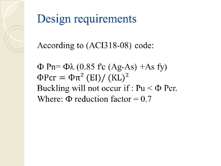
Design Requirements: �
Reinforcement for all columns in block 1 No. of column C 1 Section (cm×cm) 45× 45 rebar percentage 1% AS (mm 2) 2025 C 2 # of bars 10Ø 16 1Ø 10/10 cm 45× 45 1. 49% 2066 11Ø 16 1Ø 10/10 cm C 3 45× 45 1% 2025 10Ø 16 1Ø 10/10 cm C 4 45× 45 1. 12% 2343 12Ø 16 1Ø 10/10 cm C 5 45× 45 1% 2025 10Ø 16 1Ø 10/10 cm C 6 45× 45 1% 2025 10Ø 16 1Ø 10/10 cm C 7 45× 45 1% 2025 10Ø 16 1Ø 10/10 cm C 8 45× 45 1% 2025 10Ø 16 1Ø 10/10 cm C 9 45× 45 1% 2025 10Ø 16 1Ø 10/10 cm C 10 45× 45 1% 2025 10Ø 16 1Ø 10/10 cm Section in column 1 Ties
Reinforcement for all columns in block 2 No. of column Section AS (mm 2) Ties C 11 25× 50 rebar percentage 1% C 12 25× 50 1. 02% 1274 6Ø 16 1Ø 10/10 cm C 13 25× 50 1. 23% 1537 8Ø 16 1Ø 10/10 cm C 14 25× 50 1. 12% 1250 6Ø 16 1Ø 10/10 cm C 15 25× 50 1% 1250 6Ø 16 1Ø 10/10 cm C 16 25× 50 1% 1250 6Ø 16 1Ø 10/10 cm C 17 25× 50 1% 1250 6Ø 16 1Ø 10/10 cm C 18 25× 50 2. 69% 3369 8Ø 25 1Ø 10/10 cm (cm×cm) Section in column 2 1250 # of bars 6Ø 16 1Ø 10/10 cm
Footings Design
Design requirements � The selected footings in this project are pile footings since the project is located in Jericho, where the soil is very poor. � Piles is designed to carry one floor at block 1 and three floors at block 2. Based on the soil type in Jericho , the following assumptions are used: o Ø = 21˚ o γ = 17 KN/m² o C = 12 �
Design requirements �
Selection of pile length & diameter Results of Bearing capacity at different lengths and diameters Design Chart for selecting piles
Piles Groups and design Piles grouping and characteristics: Group No. Pu Q allowable No. of piles Length (m) Diameter (m) 1 400 490 1 4 0. 6 2 700 900 1 6 0. 8 3 1250 700 2 6 0. 7 Piles groups design:
Design of the pile cap Group Number Group 1 Group 3 Cap Dimensions ( m × m) Cap depth (m) Cap reinforcement Group 1 0. 9 × 0. 9 0. 6 3Ø 20 Group 2 1. 1 × 1. 1 0. 6 4Ø 20 Group 3 1 × 3. 1 1. 2 6Ø 20
Vertical section in Pile 1 / column 1 Horizontal section in Pile 1 / column 1
Seismic Load analysis
The structure is located in Jericho area which is classified as zone 3 according to Palestine seismic zones, in Palestine seismic zones map
The UBC 97 code seismic parameters are as follows: The seismic zone factor, Z= 0. 3 (Table 16 -I) The soil is stiff soil profile, so the soil type is SD. (Table 16 -j) The importance factor, I= 1. 0 (Table 16 -k). The ductility factor, R= 5. 6 (Table 16 -n). The seismic coefficient, Ca=0. 36 (Table 16 - Q). The seismic coefficient, Cv=0. 54 (Table 16 -R)
Define response spectrum function
Define load cases
Define load case data
Design of Slabs for seismic load Bending resistance: (Block. 1) Mu-ve = 12. 5 KN. m As =360 mm² Use 3 Ф 14/m Mu+ve = 13. 6 KN. m As =360 mm² Use 3 Ф 14/m
Design of Slabs for seismic load Bending resistance: (Block. 2) Mu-ve = 30. 5 KN. m As =369 mm² Use 2 Ф 16 Mu+ve = 16. 5 KN. m As = 64. 8 mm² Use 2 Ф 10
Design of Beams for seismic load Block 2 : (Beam 2) Mu-ve = 187. 25 KN. m As = 2088. 3 mm² Use 11Ø 16 Mu+ve = 117. 1 KN. m As = 1266 mm² Use 7Ø 16 Shear diagram Use 1 Ф 10/10 cm
Design of Beams for seismic load Block 1 : (Frame 2/Beam 1) Mu-ve = 72. 5 KN. m As = 554. 4 mm² Use 4Ø 16 Mu+ve = 26 KN. m As = 554. 4 mm² Use 3Ø 16 Shear diagram Use 1 Ф 10/25 cm
We are glad to hear your comments & questions about the presentation la Khaw Noor ’ Rema