Design of Machine ElementsI DEPARTMENT OF MECHANICAL ASST
![Design of Machine Elements-I DEPARTMENT OF MECHANICAL ASST. PROF. KIRAN KADAM M. E. [DESIGN]B.](https://slidetodoc.com/presentation_image/30126df2ffae848d983d1f482cef4ad0/image-1.jpg "Design of Machine Elements-I DEPARTMENT OF MECHANICAL ASST. PROF. KIRAN KADAM M. E. [DESIGN]B.")


")
")


 • Symbol: • Category: Feature of Size • Definition: Maximum")

 • • Symbol: Category: Feature of Size Definition: Least material")


 A dimension is \"a numerical value expressed")
: A tolerance is \"the total amount by")


 based on absolute values of deviations, and")


 the symbol, and")
- Slides: 112
Design of Machine Elements-I DEPARTMENT OF MECHANICAL ASST. PROF. KIRAN KADAM M. E. [DESIGN]B. E. [MECHANICAL]
GD&T • Datums in GD&T • Symbol:
Feature Control Frame • Example Frame:
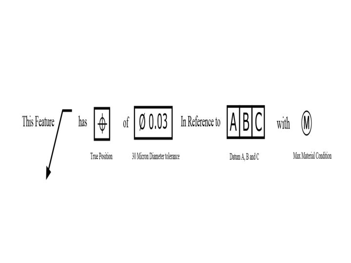
Parts of the Feature Control Frame
• • Leader Arrow – This arrow points to the feature that the geometric control is placed on. If the arrow points to a surface than the surface is controlled by the GD&T. If it points to a diametric dimension, then the axis is controlled by GD&T. The arrow is optional but helps clarify the feature being controlled. Geometric Symbol – This is where your geometric control is specified. See our page on GD&T symbols or the sidebar for a description of each symbol. Diameter Symbol (if required) – If the geometric control is a diametrical tolerance then the diameter symbol (Ø) will be in front of the tolerance value. Tolerance Value – If the tolerance is a diameter you will see the Ø symbol next to the dimension signifying a diametric tolerance zone. The tolerance of the GD&T is in whatever unit of measure that the drawing is written in. All of our examples on GD&T basics are metric units. Feature of Size or Tolerance Modifiers (if required) – This is where you call out max material condition or a projected tolerance in the feature control frame. See the Modifiers section of the GD&T Symbols page for further clarification on these features. Primary Datum (if required) – If a datum is required, this is the main datum used for the GD&T control. The letter corresponds to a feature somewhere on the part which will be marked with the same letter. This is the datum that must be constrained first when measuring the part. Note: The order of the datum is important for measurement of the part. The primary datum is usually held in three places to fix 3 degrees of freedom Secondary Datum (if required) – If a secondary datum is required, it will be to the right of the primary datum. This letter corresponds to a feature somewhere on the part which will be marked with the same letter. During measurement, this is the datum is fixated after the primary datum. Tertiary Datum (if required) – If a third datum is required, it will be to the right of the secondary datum. This letter corresponds to a feature somewhere on the part which will be marked with the same letter. During measurement, this is the datum is fixated last.
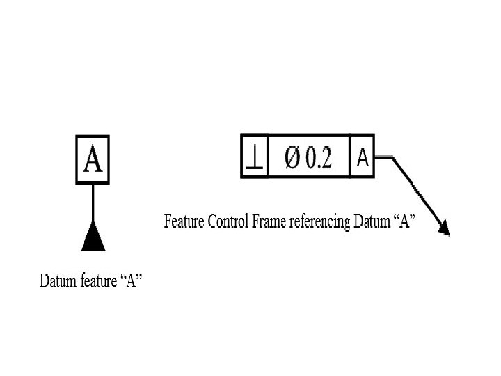
• Definition: • A datum is theoretical exact plane, axis or point location that GD&T or dimensional tolerances are referenced to. You can think of them as an anchor for the entire part; where the other features are referenced from. A datum feature is usually an important functional feature that needs to be controlled during measurement as well.
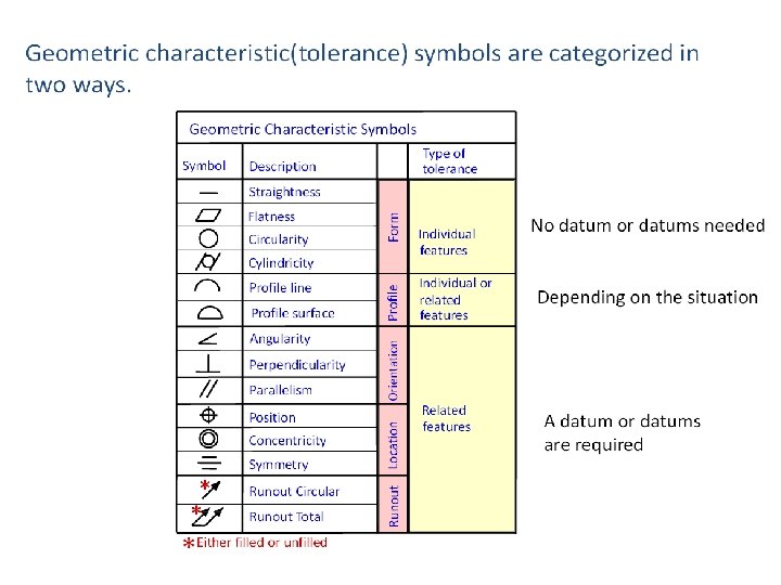
• All GD&T symbols except for the form tolerances (straightness, flatness, circularity and cylindrici ty) can use datums to help specify what geometrical control is needed on the part. When it comes to GD&T, datum symbols are your starting points where all other features are referenced from.
How Datum Features are Shown on a Drawing • The datum features on a drawing are denoted with a series of capital letters. These letters are in boxes and tied to the datum feature with a black triangle. This letter will also show up in any feature control frame that uses this datum feature as a reference. A feature control frame can reference multiple datums at once and each one can be referenced as many times as needed.
Notation is Important on Drawings • As stated before, datums can be located on points, axes, edges, and surfaces. It is important though that they is called out correctly on the drawing to control the right type of feature. Here is how different types of features are called out on engineering drawings.
On a surface
On an Axis
True Position • True Position: • Symbol: • Relative to Datum: Yes • MMC or LMC applicable: Yes (common)
True center position of a hole (RFS w/ 2 Datums)
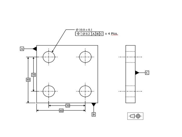
Position of a hole under MMC (3 Datums)
GD&T Tolerance Zone:
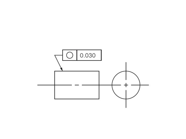
Circularity • GD&T Symbol: • Relative to Datum: No • MMC or LMC applicable: No
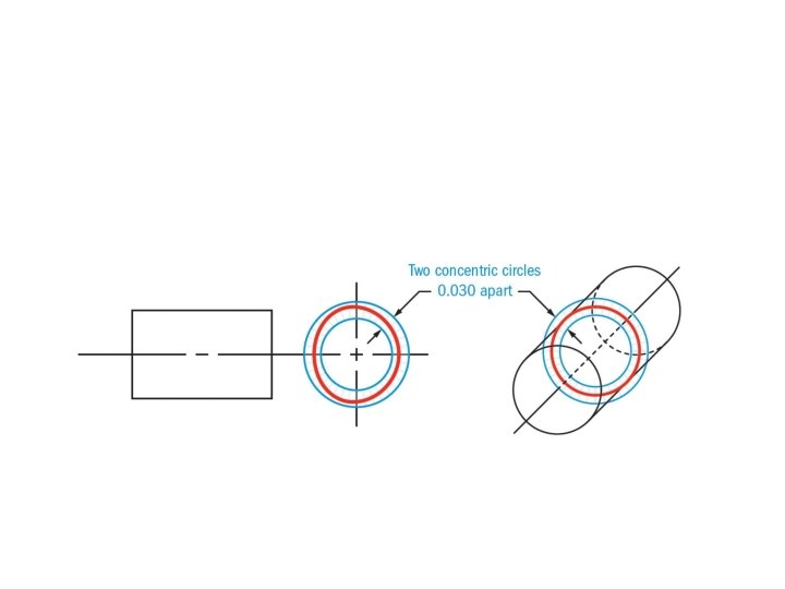
GD&T Tolerance Zone: • Two concentric circles, one inner and one outer, in which all the points within the curcular surface must fall into. The tolerance zone lies on a plane that is perpendicular to the central axis of the circular feature.
Example:
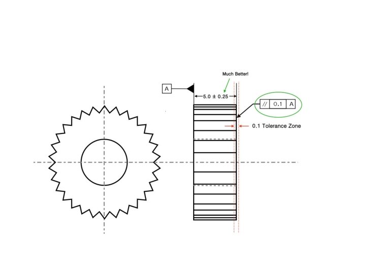
Parallelism • • GD&T Symbol: Relative to Datum: Yes MMC or LMC applicable: Yes GD&T Drawing Callout:
Gauging / Measurement:
Parallelism Example:
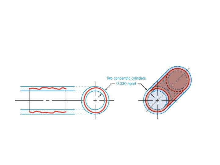
Cylindricity • • GD&T Symbol: Relative to Datum: No MMC or LMC applicable: No Drawing Callout:
GD&T Tolerance Zone: • Two concentric cylinders that run the entire length of the feature – one inner and one outer, in which all the points on the entire surface of the cylindrical feature must fall into. The entire length of the called out feature would be controlled.
Example:
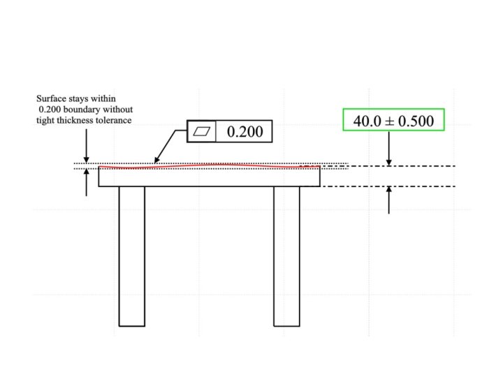
Profile of a Surface • GD&T Symbol: • Relative to Datum: Optional • MMC or LMC applicable: No
Gauging / Measurement:
Example:
Runout • • GD&T Symbol: Relative to Datum: Yes MMC or LMC applicable: No Drawing Callout
Gauging / Measurement:
Example:
Concentricity • • GD&T Symbol: Relative to Datum: Yes MMC or LMC applicable: No Drawing Callout:
Gauging / Measurement:
Example:
Example:
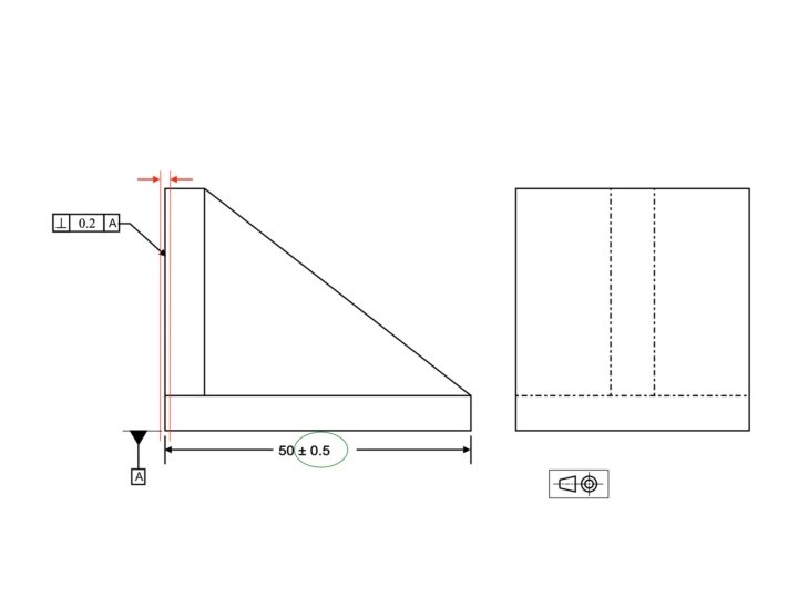
Perpendicularity • GD&T Symbol: • • Relative to Datum: Yes MMC or LMC applicable: Yes GD&T Drawing Callout: Surface Perpendicularity:
Surface Perpendicularity:
Axis Perpendicularity:
GD&T Tolerance Zone: Surface:
Axis:
Gauging / Measurement: • Surface:
Axis:
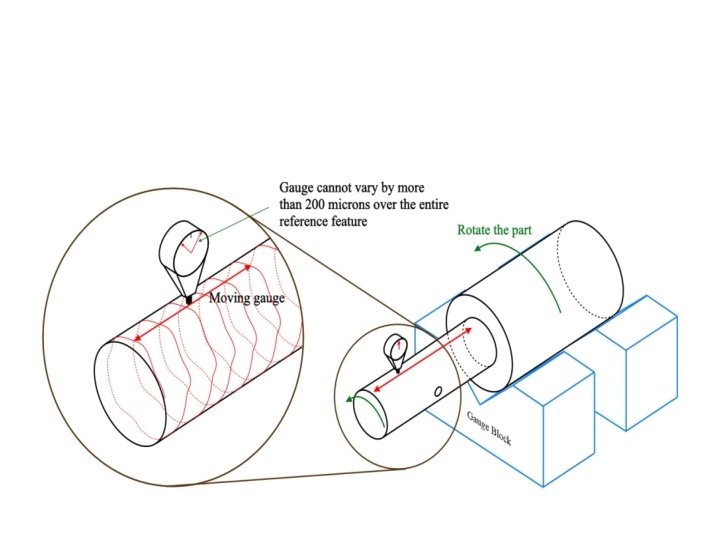
Total Runout • • GD&T Symbol: Relative to Datum: Yes MMC or LMC applicable: No Drawing Callout:
Gauging / Measurement:
Example:
Profile of a Line • • GD&T Symbol: Relative to Datum: Optional MMC or LMC applicable: No Drawing Callout:
Gauging / Measurement:
Example
Angularity • • GD&T Symbol: Relative to Datum: Yes MMC or LMC applicable: Yes (Uncommon) Drawing Callout:
Gauging / Measurement:
Angularity
Straightness • GD&T Symbol: • Relative to Datum: No • MMC or LMC applicable: Yes – Axis Straightness • Drawing Callout:
Surface Straightness
Axis Straightness with Maximum Material Condition
Gauging / Measurement: • Surface:
Symmetry • • GD&T Symbol: Relative to Datum: Yes MMC or LMC applicable: No Drawing Callout:
Gauging / Measurement:
Example:
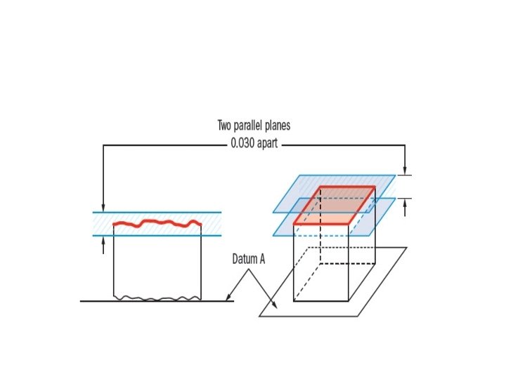
Flatness • • Symbol: Relative to Datum: No MMC or LMC applicable: Yes – New in 2009 Drawing Callout
Gauging / Measurement:
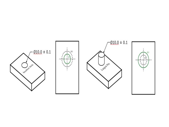
Maximum Material Condition (MMC) • Symbol: • Category: Feature of Size • Definition: Maximum Material Condition or for short, MMC, is a feature of size symbol that describes the condition of a feature or part where the maximum amount of material (volume/size) exists within its dimensional tolerance.
The only GD&T Symbols where Max Material Condition can be applied are: • • • Straightness (axis) Parallelism Perpendicularity Angularity True Position – very common
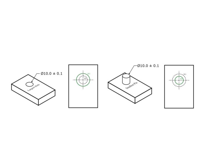
Least Material Condition (LMC) • • Symbol: Category: Feature of Size Definition: Least material condition is a feature of size symbol that describes a dimensional or size condition where the least amount of material (volume/size) exists within its dimensional tolerance.
DIMENSIONS, TOLERANCES, AND SURFACES 1. Dimensions, Tolerances, and Related Attributes 2. Conventional Measuring Instruments and Gages 3. Surfaces 4. Measurement of Surfaces 5. Effect of Manufacturing Processes
Dimensions and Tolerances • Factors that determine the performance of a manufactured product, other than mechanical and physical properties, include : – Dimensions - linear or angular sizes of a component specified on the part drawing – Tolerances - allowable variations from the specified part dimensions that are permitted in manufacturing
Dimensions (ANSI Y 14. 5 M‑ 1982) A dimension is "a numerical value expressed in appropriate units of measure and indicated on a drawing and in other documents along with lines, symbols, and notes to define the size or geometric characteristic, or both, of a part or part feature" • The dimension indicates the part size desired by the designer, if the part could be made with no errors or variations in the fabrication process
Tolerances (ANSI Y 14. 5 M‑ 1982): A tolerance is "the total amount by which a specific dimension is permitted to vary. The tolerance is the difference between the maximum and minimum limits" • Variations occur in any manufacturing process, which are manifested as variations in part size • Tolerances are used to define the limits of the allowed variation
Bilateral Tolerance • Variation is permitted in both positive and negative directions from the nominal dimension • Possible for a bilateral tolerance to be unbalanced – Ex: 2. 500 +0. 010, -0. 005
Unilateral Tolerance • Variation from the specified dimension is permitted in only one direction • Either positive or negative, but not both
Limit Dimensions • Permissible variation in a part feature size consists of the maximum and minimum dimensions allowed
Accuracy and Precision Accuracy - the degree to which a measured value agrees with the true value of the quantity of interest • A measurement procedure is accurate when it avoids systematic errors (positive or negative deviations that are consistent from one measurement to the next) Precision - the degree of repeatability in the measurement process • Good precision means that random errors in the measurement procedure are minimized
Conventional Measuring Instruments and Gages • • • Precision gage blocks Measuring instruments for linear dimensions Comparative instruments Fixed gages Angular measurements
Precision Gage Blocks Standards against which other dimensional measuring instruments and gages are compared • Usually square or rectangular blocks • Surfaces are finished to be dimensionally accurate and parallel to several millionths of an inch and are polished to a mirror finish • Precision gage blocks are available in certain standard sizes or in sets, the latter containing a variety of different sized blocks
Measurement of Linear Dimensions • Measuring instruments are divided into two types: – Graduated measuring devices include a set of markings on a linear or angular scale to which the object's feature of interest can be compared for measurement – Nongraduated measuring devices have no scale and are used to compare dimensions or to transfer a dimension for measurement by a graduated device
Micrometer • External micrometer, standard one‑inch size with digital readout (photo courtesy of L. S. Starret Co. )
Calipers • Two sizes of outside calipers (photo courtesy of L. S. Starret Co. )
Mechanical Gages: Dial Indicators • Mechanical gages are designed to mechanically magnify the deviation to permit observation • Most common instrument in this category is the dial indicator, which converts and amplifies the linear movement of a contact pointer into rotation of a dial – The dial is graduated in small units such as 0. 01 mm or 0. 001 inch – Applications: measuring straightness, flatness, parallelism, squareness, roundness, and runout
Dial Indicator • Front view shows dial and graduated face; back view shows cover plate removed (photo courtesy of Federal Products Co. )
Dial Indicator Setup to Measure Runout • As part is rotated about its center, variations in outside surface relative to center are indicated on the dial
Electronic Gages Family of measuring and gaging instruments based on transducers capable of converting a linear displacement into an electrical signal • Electrical signal is amplified and transformed into suitable data format such as a digital readout • Applications of electronic gages have grown rapidly in recent years, driven by advances in microprocessor technology, and are gradually replacing many of the conventional devices
GO/NO‑GO gages So-named because one gage limit allows the part to be inserted while the other limit does not • GO limit - used to check the dimension at its maximum material condition – Minimum size for internal feature such as a hole – Maximum size for external feature such as an outside diameter • NO‑GO limit - used to inspect the minimum material condition of the dimension in question
Snap Gage • Gaging the diameter of a part (difference in height of GO and NO‑GO gage buttons is exaggerated)
Plug Gage • Gaging of a hole diameter (difference in diameters of GO and NO-GO plugs is exaggerated)
Measurement of Angles • Bevel protractor with Vernier scale (courtesy L. S. Starrett Co. )
Surfaces Nominal surface – designer’s intended surface contour of part, defined by lines in the engineering drawing – Nominal surfaces appear as absolutely straight lines, ideal circles, round holes, and other edges and surfaces that are geometrically perfect • Actual surfaces of a part are determined by the manufacturing processes used to make them – Variety of processes result in wide variations in surface characteristics
Why Surfaces are Important • Aesthetic reasons • Surfaces affect safety • Friction and wear depend on surface characteristics • Surfaces affect mechanical and physical properties • Assembly of parts is affected by their surfaces • Smooth surfaces make better electrical contacts
Surface Technology • Concerned with: – – Defining the characteristics of a surface Surface texture Surface integrity Relationship between manufacturing processes and characteristics of resulting surface
Metallic Part Surface • Magnified cross section of a typical metallic part surface
Surface Texture The topography and geometric features of the surface • When highly magnified, the surface is anything but straight and smooth – It has roughness, waviness, and flaws • It also possesses a pattern and/or direction resulting from the mechanical process that produced it
Surface Texture • Repetitive and/or random deviations from the nominal surface of an object
Four Elements of Surface Texture 1. Roughness - small, finely‑spaced deviations from nominal surface – Determined by material characteristics and processes that formed the surface 2. Waviness - deviations of much larger spacing – Waviness deviations occur due to work deflection, vibration, tooling, and similar factors – Roughness is superimposed on waviness
Four Elements of Surface Texture 3. Lay - predominant direction or pattern of the surface texture
Four Elements of Surface Texture 4. Flaws - irregularities that occur occasionally on the surface – Includes cracks, scratches, inclusions, and similar defects in the surface – Although some flaws relate to surface texture, they also affect surface integrity
Surface Roughness and Surface Finish • Surface roughness - a measurable characteristic based on roughness deviations • Surface finish - a more subjective term denoting smoothness and general quality of a surface – In popular usage, surface finish is often used as a synonym for surface roughness – Both terms are within the scope of surface texture
Surface Roughness Average of vertical deviations from nominal surface over a specified surface length
Surface Roughness Equation • Arithmetic average (AA) based on absolute values of deviations, and is referred to as average roughness where Ra = average roughness; y = vertical deviation from nominal surface (absolute value); and Lm = specified distance over which the surface deviations are measured
Alternative Surface Roughness Equation • Approximation of previous equation is perhaps easier to comprehend where Ra has same meaning as above; yi = vertical deviations (absolute value) identified by subscript i; and n = number of deviations included in Lm
Cutoff Length • A problem with the Ra computation is that waviness may get included • To deal with this problem, a parameter called the cutoff length is used as a filter to separate waviness from roughness deviations • Cutoff length is a sampling distance along the surface – A sampling distance shorter than the waviness eliminates waviness deviations and only includes roughness deviations
Surface Roughness Specification • Surface texture symbols in engineering drawings: (a) the symbol, and (b) symbol with identification labels