Design of Kaplan Turbine P M V Subbarao

Design of Kaplan Turbine P M V Subbarao Professor Mechanical Engineering Department Pure Axial Flow with Aerofoil Theory….

Design of A Kaplan Turbine

Selection of Kaplan Turbine MORE ADAPTED TYPE OF TURBINA IN FUNCTION OF THE SPECIFIC SPEED. Specific Speed in r. p. m. Turbine type Jump height in m From 270 to 500 Slow Kaplan 50 to 15 From 500 to 800 Quick Kaplan 15 to 5 From 800 to 1100 Extra-quick Kaplan Less than 5 P in hp and H in meters.

Specific Speed of Kaplan Turbine • Using statistical studies of schemes, F. Schweiger and J. Gregory established the following correlation between the specific speed and the net head for Kaplan turbines: P in watts.

The Schematic of Kaplan Turbine

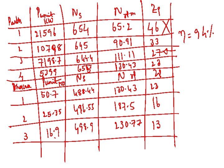
Major Parts of A Kaplan Turbine P, in hp and H in meters.

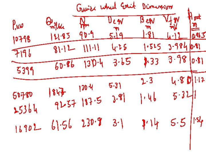
Design of Guide Wheel Degv

Kug Kfg

Outlines of Kaplan Runner a b Guide Vanes Whirl Chamber The space between guide wheel outlet and kaplan runner is known as Whirl Chamber. a=0. 13 Drunner & b=0. 16 to 0. 2 Drunner.

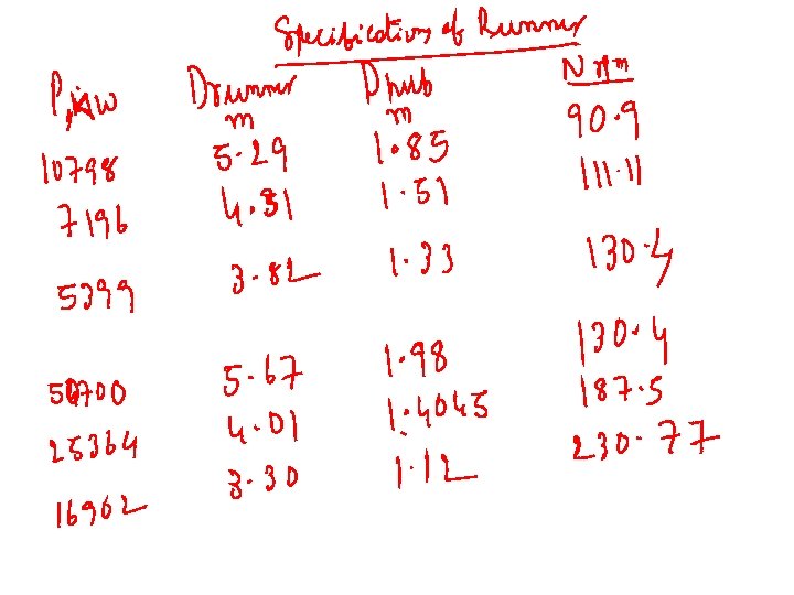
Design of Kaplan Runner Drunner Dhub

Testing of Runner diameter selection The runner diameter De can be calculated by the following equation: n in rps

Runner diameter section • The hub diameter Dhub can be calculated with the following equation:

Kug Qfactor

Number of runner Vanes Vs Guide Wheel Diameter Z Dge, mm 8 10 12 14 16 <300 – 450 – 750 – 1200 – 1600 18 20 24 1600 2200 >4000

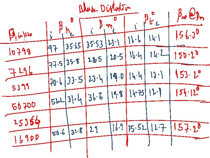
DESIGN OF THE BLADE Two different views of a blade

Hydrodynamics of Kaplan Blade

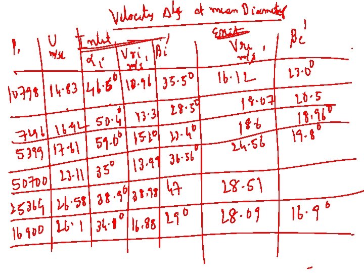
Distortion of the blade under ideal circumstances • The velocity triangles, which occur on the blade, play a significant role in determining its distortion. a 1 < 900 Uwheel V ai V ri Vfi

Uwheel Details of Blade Arrangement V ai Uwheel V ae V re ae = 900 Vfe V ri Vfi

Inlet Velocity Triangles Vs Ns High Specific Speed : Fast Francis Runner Vwi Vai Vfi

Specifications of Runner • • • Slow Runner: Ns=60 to 120 – ai = 150 to 250 – Kui = 0. 62 to 0. 68 – bi = 900 to 1200 – Bgv/Dmgv=0. 04 – 0. 033 Normal Runner: Ns = 120 – 180 – ai = 250 to 32. 50 – Kui = 0. 68 to 0. 72 – bi = 900 – Bgv/Dmgv=0. 125 to 0. 25 Fast Runner: Ns = 180 to 300 – ai = 32. 50 to 37. 50 – Kui = 0. 72 to 0. 76 – bi = 600 to 900 – Bgv/Dmgv=0. 25 to 0. 5

Design for Maximum Power Retrieval Inlet Velocity Triangle Uwheel V ai V ri Vfi


Radial Equilibrium Equation for Incompressible Fluid Machine

To define the distortion of the blade, the velocity triangles of at least six different radiuses of the blade are to be determined. The angle β of each radius gives conclusions on the distortion of the blade. The angles should be corrected for real hydraulics.

General Rules for Selection of Whirl Component • Free Vortex Whirl: • Forced Vortex Whirl :

Method for Selection of Blade Shape Define Half Travel Point of a fluid particle as Vre Vfi=Vfe V∞ Vri

The “Tragflügeltheorie” V∞ Factual lift Fideal lift

Vri

Hydraulic Energy Diagram Hm Hre Hri Htotal Hs

Characteristics of A Single Blade • Ideal Blade lift coefficient: hdraft: Efficiency of draft tube: 0. 88 to 0. 91 K : Profile characteristic number: 2. 6 to 3. 0 hmin=Head equivalent to minimum allowable pressure at Runner exit.

The suction head • The suction head Hs is the head where the turbine is installed; • if the suction head is positive, the turbine is located above the trail water; • if it is negative, the turbine is located under the trail water. • To avoid cavitation, the range of the suction head is limited. • The maximum allowed suction head can be calculated using the following equation:

When the lifting coefficient is known, the sufficiency of ratio l/t can be established as follows: Allowable values of angle of slip l 2. 5°-- 3°

The actual Lifting Coefficient

1. 2 R 2 = 0. 9946 1 0. 8 0. 6 0. 4 0. 2 0 0 0. 5 1 1. 5 2 2. 5 3 3. 5 4 4. 5

Drag Coefficient

Calculation of Actual Angle of Slip

Uwheel Details of Blade Arrangement V ai Uwheel V ae V re ae = 900 Vfe V ri Vfi

Actual Angle of Attack


Power Developed by the Runner Power developed by a differential blade surface
- Slides: 45