Design of Foundation for Saada building in Nablus

Design of Foundation for Sa’ada building in Nablus Prepared by : Hilda Abu Baker Neama Khlouf Raghad Saqf Alhait Submitted to: Dr. Muhammad Ghazal

Objectives: ØGeneral description of the project. ØStructural system. ØGeotechnical conditions of the site. ØDesign of two types of foundation.

General description of the project The project is about designing appropriate foundation of a building in Almakhfeye Street which has very week soil so we will give suitable solutions for the problem in this soil under which building is constructed.

Structural System Dead load: We assume dead load equal 11 KN/m 2. Live load. we assume the value of live load 7 KN/m 2 for ground floor and 3 KN/m 2 for other floors.

Columns layout

Loads on columns We calculate loads by tributary area method and the results as follow

column number col. Dim P service P ultimate 1 60*20 469. 2 597. 3 2 20*60 960. 6 1231. 1 3 20*70 1096. 6 1411. 2 4 20*60 898. 2 1153. 6 5 60*20 1636. 8 2122. 1 6 20*60 1621. 7 2102. 6 7 20*205 1302. 9 1675. 8 8 20*60 823. 6 1057. 8 9 20*70 1764. 4 2287. 6 10 20*60 1589. 2 2060. 5 11 30*70 681. 4 870. 6 12 60*20 458. 8 585. 1 13 20*60 1011. 8 1297. 7 14 20*60 904. 7 1159. 9 15 20*60 355. 2 451. 8 16 shear wall 482. 6 625. 7

Also we determine the load by using SAFE program and the result as follow

In order to compare load from tributary area with safe load we take c 13 and c 14 as an example C 13: %Error=(1297. 664 -1194)/1194=8. 6% acceptable C 14: %Error=(1159. 8 -1076. 7)/1076. 76=7. 7% acceptable

Geotechnical Conditions of the site The main soil description of the site states that it consist mainly of weak silty clay formation with occasional boulders to the full depth of exploration and the whole site is covered by a layer of fill material of rocks and boulders.

Ø From soil investigation report we take: ɸ = 19 C = 23 KNm 2 Unit weight for soil =18 KNm 3 Preliminary dimensions B=2 m D=1. 5 m Ø Then we determine ultimate bearing capacity by Terzagi Equation Ø Then we determine allowable bearing capacity by take factor of safety equal 2. 5. �We get qult = 505. 5 KN/m 2 � qall=202 KN/m 2 = 2. 02 Kg/cm 2. We use Qall = 220 KN/m 2

Design of Foundation: In our design we used two options, the first one was using the system of isolated and combined footing, and the second one was using the system of mat (raft) foundation.

Design of Foundation: We found the preliminary area for each footing by using equation: Where, qall = 220 KN/m 2 And the results as follow:

Design of Foundation: column number 1 2 3 4 5 6 7 8 9 10 11 12 13 14 15 P service 469. 2 960. 6 1096. 6 898. 2 1636. 8 1621. 7 1302. 9 823. 6 1764. 4 1589. 2 681. 4 458. 8 1011. 8 904. 7 355. 2 Area 2. 1 4. 4 5. 0 4. 1 7. 4 5. 9 3. 7 8. 0 7. 2 3. 1 2. 1 4. 6 4. 1 1. 6 L=B 1. 5 2. 1 2. 2 2. 0 2. 7 2. 4 1. 9 2. 8 2. 7 1. 8 1. 4 2. 1 2. 0 1. 3

Design of Foundation: Then we draw it using Auto. CAD.

Design of Foundation: System of isolated and combined footing: � For design purposes we tried to unifie the footing under columns with approximate equal loads, where: • F 1 for C 1, C 12 • F 2 for C 2, C 3, C 4, C 8, C 13 • F 3 for C 5, C 9 • Where, F 1 & F 2 & F 3 are combined footing • F 4 for C 7+C 6 • F 5 for C 10+C 11 • F 6 for C 14 +C 15 • Where, F 4& F 5 & F 6 are combined footing � We designed the isolated and combined footing in the same system, and we use CDS program for design. We designed one footing manually to compare between the result.

Design of Foundation: Design of isolated footing manually: Take column 9 as an example: Pservice = 1764 KN Pultimate = 2288 KN Qall=220 KN/m 2 F’c=30 MPa Fy = 420 MPa col. dim. = 20*70. σmax = P/A ≤ Qall A= 1764/220 = 8. 02 m 2 Assume B=2. 5 m & L=8. 02/2. 5 = 3. 2 m
")
Design of Foundation: Thickness: Punching control σmaxult = Pu/A = 2288/ (2. 5*3. 2) = 286 KN/m 2.
 + 2* (200+d) = 1800+4 d Vu=")
Design of Foundation: b 0 = 2*(700+d) + 2* (200+d) = 1800+4 d Vu= Pu = 2288 KN H=550 mm.

Design of Foundation: Check this thickness for wide beam shear : Vu = 286 *(1. 25 -0. 5) = 214. 5 KN/m

Design of Foundation: Reinforcement: Uniform stress equal 286 KN/m 2 Long direction : L=1. 25 m B=1000 mm , , d =500 mm , , h=550 mm As = 0. 00241 * 1000 * 500 = 1205 mm 2/mm Asmin = 0. 0018*1000 *550 = 990 As > As min … use As

Design of Foundation: Other direction : L = 1. 15 m > As min Longitudinal steel can be distributed uniformly : As = 1205 mm 2/ mm , , use 6φ16 / m Transverse steel : As = 1019 mm 2/mm Total As = 3. 2 *1019 = 3567 mm 2/mm As 2 = 3567 – 3129 = 438 mm 2/ mm As min = 0. 0018 * 350 * 550 = 347 > (438/2) , , , use As min

Design of Foundation: Design of combined footing manually: Take Column 11 & 10 as example : 681. 4*0 +1589. 2*2. 3= 2280. 6*X X=1. 6 m Uniform stress σ max < Qall , , , we assume B=2. 3 m , , L=4. 5 m

Design of Foundation:

Design of Foundation: Thickness : For meter width = 283 * 2. 3 = 651. 4 KN/m

Design of Foundation:

Design of Foundation: The critical is 1050. 6 KN thus : Vu=1050. 6 – 651. 4*(0. 3+d/1000) = 855. 2 - 0. 6514 d d=0. 384 m , , , take d=0. 5 m
 Footing Design by CDS 3 m. Ver:")
Design of Foundation: Result from program: (CDS) Footing Design by CDS 3 m. Ver: the program CDS 3 m. Ver 2 design the footing by assume dimensions and thickness for specific load which footing is exposed to it , and this program gives if this dimensions satisfy Qall and the punching is ok. In addition, it also gives another choices for dimension and thickness that suitable for design.

Design of Foundation: We was using 60 ton for design F 1:

Design of Foundation: We using 120 ton for design F 2

Design of Foundation: We using 320 ton for design F 3

Design of Foundation: Footing 4 , 5 & 6 we using the load that in the column : F 4:

Design of Foundation: F 5:

Design of Foundation: F 6:

Design of Foundation: footings dimension from program :

Design of Foundation: Reinforcement of footing :

 Foundation System: We use SAFE program in order")
Design of Foundation: Design of Mat(Raft) Foundation System: We use SAFE program in order to design Mat foundation.

Design of Foundation: Loads on columns

Design of Foundation: We use thickness of mat foundation to be 70 cm then we check it by display punching on columns and all results found less than 1 and it is ok.

Design of Foundation: The distribution of steel that we get from SAFE program as follow: One direction top bar:

Design of Foundation: One direction bottom bar:

Design of Foundation: two direction top bar:

Design of Foundation: two direction bottom bar:

Design of Foundation: Also, we check the settlement by show deformed shape and we find that the largest settlement equals 7 mm around the largest column ( column No. 7).

Design of Foundation: Mat foundation reinforcement :

Design of Foundation:

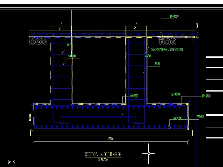
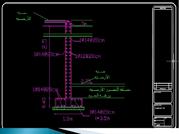
Design of basement wall: We assume the basement wall as a continuous beam that the base is fixed and the pin is the wall. We use broken to design it.

Design of basement wall: The load distribution in the span of basement :

Design of basement wall: Vu=99. 82 KN @3 m Mu=67. 2 KN @0 m

Design of basement wall: Reinforcment : As=745 mm 2 from the graph

Design of basement wall: � Asmin=. 0025*100*30=7. 5 cm 2/m =7. 5 cm^2/m>7. 45 cm 2/m � Then we use Asmin So: 1 Ɵ 14/20 cm in long direction � In the short direction for shrinkage: � As=0. 0018*b*h =0. 0018*100*30 =5. 4 cm 2/m So we use: � 1Ɵ 12/20 cm

Design of basement wall: � Design the base :

Design of basement wall: � Asmin=0. 0018*b*h for the base =0. 0018*100*40 =7. 2 cm 2/m > 3. 18 cm 2/m
 the reinforcement less than min")
Design of basement wall: � In the (prokon program) the reinforcement less than min but we adjust it in the program to use As min � Which is: As min=7. 2 cm 2/m so we use 1 Ɵ 14/20 cm in two direction and top and bottom.

- Slides: 58