Design of Components of Francis Turbine P M

Design of Components of Francis Turbine P M V Subbarao Professor Mechanical Engineering Department Detailing to Infuse Reaction….

Specific speed in rpm P in hp & H in meters

Selection of Speed of A Turbo Machine Zp : Number of pairs of poles of the generator

Unit Sizing

Design of Any Selected Francis Turbine Unit • • Different capacities for each sub-group. Design for Normal Head. Assume an overall efficiency: 94 – 96% Calculate the required flow rate.

General Layout of A Hydro Power Plant Power Tunnel: Diameter: 15000 mm Length= 746 m Slope= 1 in 120 Actual velocity: 5. 563 m/s

Power Tunnel Channel Bed Slope

Penstock : Consider Velocity equal to Actual Site Velocity

Pipe Material drawn brass drawn copper commercial steel wrought iron asphalted cast iron galvanized iron cast iron wood stave Absolute Roughness, e micron (unless noted) 1. 5 45 45 120 150 260 0. 2 to 0. 9 mm concrete 0. 3 to 3 mm riveted steel 0. 9 to 9 mm Estimate net Head available at the inlet turbine casing

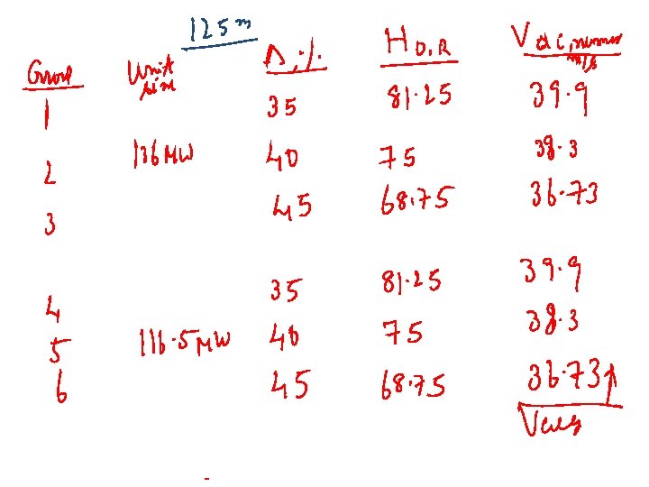
Dimensions of Penstock Group NO. Unit Size MW Degree of Reaction, % 1 35 2 40 3 45 4 35 5 40 6 45 Dpenstock m Vpenstock m/s Head loss m

Design of Spiral Casing dpenstock Rcasing Q Risv Inlet to Stay vanes

Runner ng es Ri e van Guid Stay vanes Ring

Design of the Guide Vanes How to choose the guide vane angle aegv at full load aegv

Specifications of Guide Vanes • Slow Runner: Ns=60 to 120 – Begv/Dmgv=0. 033 – 0. 04 • Normal Runner: Ns = 120 – 180 – Begv/Dmgv=0. 125 to 0. 25 • Fast Runner: Ns = 180 to 300 – Begv/Dmgv=0. 25 to 0. 5 e n a fv o h gt n e l L: L 5 =1 t 0% 3 o of gv e D

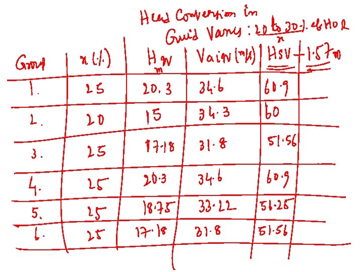
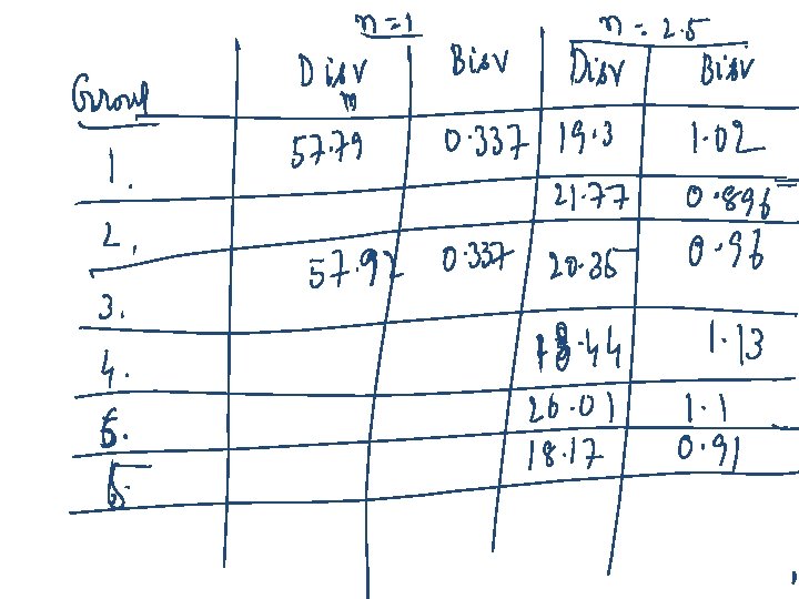
Dimensions of Guide Vane Wheel Group NO. Unit Size MW Degree of Reaction, % 1 35 2 40 3 45 4 35 5 40 6 45 Digv, m Degv, m Bgv, m

Dimensions of Guide Vane Wheel Group NO. Unit Size MW Degree of Reaction, % 1 35 2 40 3 45 4 35 5 40 6 45 Digv, m Degv, m Bgv, m

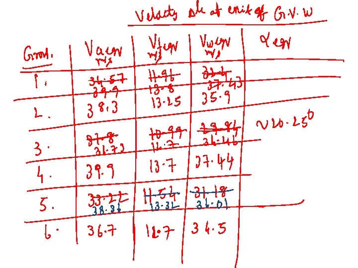
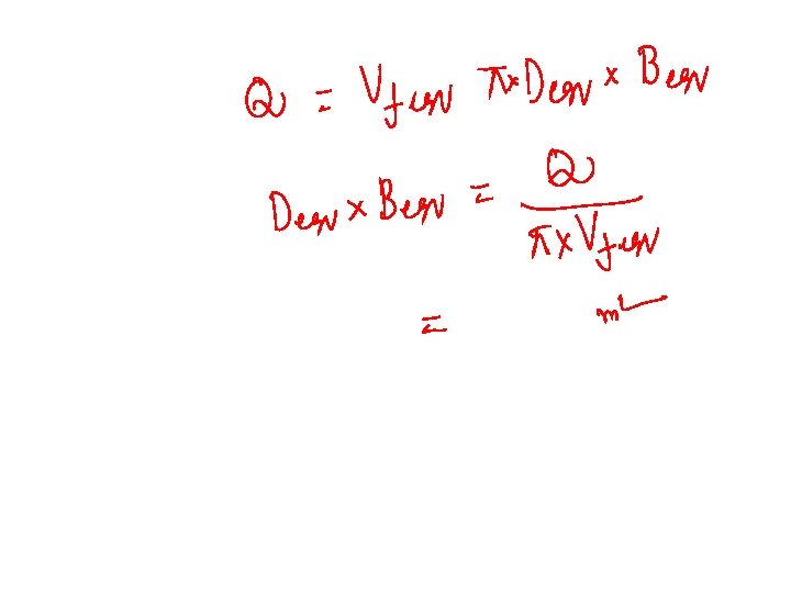
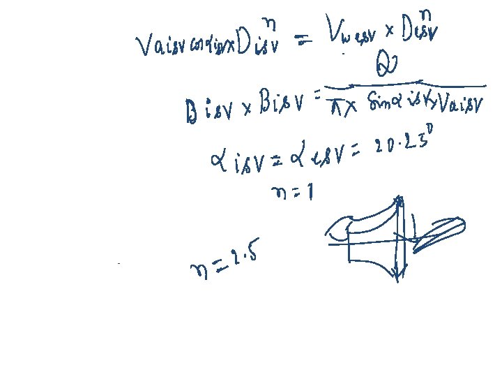
Design of the Guide Vane Inlet Angle • The outlet angle can be calculated by assuming a vortex from the flow in the gap between the runner and the guide vanes Begv Select appropriate value of n regv rigv
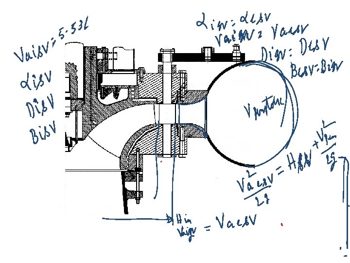


Design of the Details of Stay Vanes Theory of Relatively Whirling flow: Besv rexit stay Vane rinlet Stay Vane Bisv

At any angle q, the radius of casing is: A full spiral is generally recommended for high head 300 m, semi-spiral is recommended for low heat <50 m. In general k =1. 0, however corrected using CFD.

Performance of Casing : Loss of Total Pressure dpenstock Q Rcasing Risv The losses in the spiral casing as a sum f distributed losses and the exit losses

Friction losses in the spiral casing and stay vanes Guide vane losses Gap losses Runner losses Draft tube losses

Number of Guide/stay Vanes Ns Z=8 10 12 14 16 18 20 24 <200 <250 - 400 - 600 - 800 - 1000 400 600 800 1000 1250 Dge, m m 1250 >1700 >200 1700 >2100 <300 - 450 - 750 - 1050 450 750 1050 1350 1700

Validation of the Guide Vanes Design Degree Overlapping of the guide vanes Low Overlap High Overlap

Specifications of Guide Vanes f o th L e n a v g n e : l D f o % 0 3 o t 5 1 L= egv

Minimum Number of Guide/stay Vanes Ns Z=8 10 12 14 16 18 20 24 <200 <250 - 400 - 600 - 800 - 1000 400 600 800 1000 1250 Dge, m m 1250 >1700 >200 1700 >2100 <300 - 450 - 750 - 1050 450 750 1050 1350 1700

The Runner

Velocity triangles rri Vwi Uri ai Vfi Vai rre Vwe ae Vae Ure Vfe be Vre bi Vri

Water particle Water from spiral casing

Diameter of guide vane shaft Vs Runner Inlet Diameter Dmgv DRI DRE

Design of the Runner Vanes How to choose the number of vanes • The number of guide vanes has to be different from the number of runner vanes.

Ub Vwi Vri Vai Ub Vwi Vfi Vai Vfi Vri Vfi

Inlet Velocity Triangles Vs Ns Low Specific Speed : Slow Francis Runner Vwi Vfi Vai

Inlet Velocity Triangles Vs Ns Low Specific Speed : Normal Francis Runner Vwi Vai Vfi

Inlet Velocity Triangles Vs Ns High Specific Speed : Fast Francis Runner Vwi Vai Vfi

Specifications of Runner • • • Slow Runner: Ns=60 to 120 – ai = 150 to 250 – Kui = 0. 62 to 0. 68 – bi = 900 to 1200 – Bgv/Dmgv=0. 04 – 0. 033 Normal Runner: Ns = 120 – 180 – ai = 250 to 32. 50 – Kui = 0. 68 to 0. 72 – bi = 900 – Bgv/Dmgv=0. 125 to 0. 25 Fast Runner: Ns = 180 to 300 – ai = 32. 50 to 37. 50 – Kui = 0. 72 to 0. 76 – bi = 600 to 900 – Bgv/Dmgv=0. 25 to 0. 5

Velocity triangles rri Vwi Uri ai bi Vfi Vai Vri rre Vwe ae Vae Ure Vfe be Vre o 13 < be < 22 o

Design for Maximum Power

Net Positive Suction Head, NPSH

NPSH required

Dimensions of the outlet 13 o < be < 1, 05 < a < 0, 05 < b < 22 o 1, 15 0, 15 Highest value for highest head

Remaining head to be used : Extra head to be converted into kinetic energy: Preferred Exit Velocity Triangle: DRI DRE 13 o < b. RE < 22 o
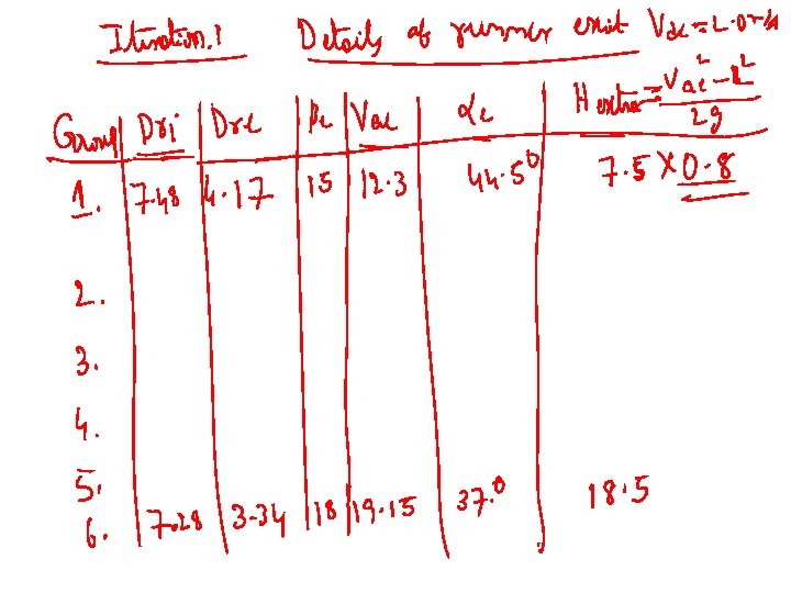

Available Inlet velocity Triangle

Runner Design
- Slides: 52