Design of An Axial Compressor Stage for Jet


- Slides: 22
Design of An Axial Compressor Stage for Jet Engines P M V Subbarao Professor Mechanical Engineering Department Efficient Infrastructure to Infuse Life into Air. . .
Irreversible Adiabatic Stage of an Axial Flow Fan/Compressor p 03 s=p 02 s p 02 p 03 T =T 03 Rotor Losses T 02 Total Losses T 03 s p 01 T 01 s
Real Flow Past Compressor Blades
Stage Efficiency of a fan or Compressor For a required pressure ratio of a stage, rop, stage The power consumed by an irreversible stage is always higher than a reversible stage. Define stage efficiency as
Actual pressure Ratio of A fan or Compressor Stage
Compressor Blade geometry Vr 1 Vr 2 i Incidence angle, 1 - b 1 Deviation angle, 2 - b 2
Selection of Design Parameters • A high pressure rise per stage will decrease the number of stages for a given overall pressure rise. • A high pressure rise per stage is obtained using: • High blade speed. • High inlet flow velocity. • High fluid deflection in rotor blades.
Blade Speed • For a given rotor speed the velocity of the blade at the tip will be maximum. • The centrifugal stress in the rotor blades depends on the rotational speed, the blade material and length of the blade. • The maximum centrifugal stress is given by, • b, hub-tip diameter ratio. • K varies in the range 0. 55 – 0. 65.
Selection of Absolute Inlet Velocity Vr 1 V a 1 Vr 1 Va 1
Selection of Flow velocity & Losses Annulus Loss Secondary Loss Pro file Los s Vf/U
Fluid Deflection
Effect of Diffusion Factor on Frictional Losses Rotor Tip Losses Rotor Hub and Stator losse
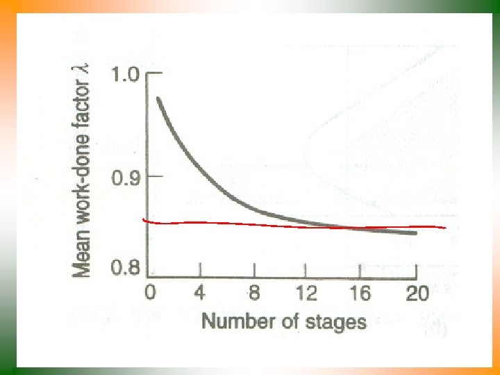
Multi Stage Compression Loss in capacity due to variation of velocity is defined as work done factor. Work done factor, l, decrease with number of stages.
Sizing of A Compressor Stage • There are five Primary non-dimensional variables • Stage load coefficient or Work input coefficient • Stage flow coefficient • Stage reaction, R • de Haller number, d. H
Holistic Method of Mean Line Design Va Vr 1 Va 1 Vw Vf Vr 2 Va 3 Vr 2 Vr 1 Va 2
Smith Design Chart : R=50%
Smith Design Chart – R = 60%
Smith Design Chart – R = 70%
Irreversible Flow through Multi Stage Fan & Compressor 1 VIs 2 s 1 Vs 1 IIIs T 4 VIa 1 IIs 1 s 4 IVa 1 IIIa 1 Ia 4 Va
Variable Speed operation of Compressor
Hybrid Compressor