
Design of a highfrequency RFQ for Carbon ion
Design of a high-frequency RFQ for Carbon ion therapy Hermann Pommerenke (BE-RF-LRF) Vittorio Bencini, Alexej Grudiev, Alessandra Lombardi & CERN Knowledge Transfer Fund 1 July 2020 H. Pommerenke, BE-RF-LRF 1

Very briefly: what is an RFQ? • accelerator of choice for low-energy hadrons up to few Me. V/u • strong electric quadrupole focusing field • modulation on quadrupole electrodes produces Ez field • accepts continuous input beam from LEBT, performs adiabatic bunching 1 July 2020 H. Pommerenke, BE-RF-LRF 2
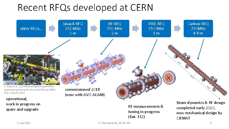
Recent RFQs developed at CERN older RFQs… C. Rossi et al. , „Commissioning and operational experience gained with the Linac 4 -RFQ at CERN”, Proc. Linac 14, 2014 operational, work in progress on spare and upgrade 1 July 2020 Linac 4 -RFQ 352 MHz 3 m HF-RFQ 750 MHz 2 m PIXE-RFQ 750 MHz 1 m Carbon-RFQ 750 MHz 4. 8 m commissioned 2018 (now with AVO ADAM) RF measurements & tuning in progress (Bat. 112) H. Pommerenke, BE-RF-LRF Beam dynamics & RF design completed early 2020, now mechanical design by CIEMAT 3
Part I: Carbon-RFQ Beam Dynamics Design 1 July 2020 H. Pommerenke, BE-RF-LRF 4

Context & initial Carbon-RFQ design • conceived by V. Bencini (BE-ABP) as first RF structure of „bent linac“ for carbon ion cancer therapy • initial design with LANL codes (PARMTEQ): • low beam current • ~ 50 % transmission • up to 5 Me. V/u (60 Me. V) 1 July 2020 H. Pommerenke, BE-RF-LRF 5
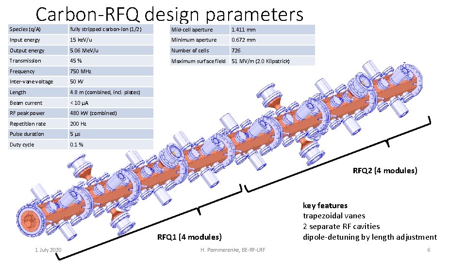
Carbon-RFQ design parameters Species (q/A) fully stripped carbon-ion (1/2) Mid-cell aperture 1. 411 mm Input energy 15 ke. V/u Minimum aperture 0. 672 mm Output energy 5. 06 Me. V/u Number of cells 726 Transmission 45 % Maximum surface field 51 MV/m (2. 0 Kilpatrick) Frequency 750 MHz Inter-vane voltage 50 k. V Length 4. 8 m (combined, incl. plates) Beam current < 10 µA RF peak power 480 k. W (combined) Repetition rate 200 Hz Pulse duration 5 µs Duty cycle 0. 1 % RFQ 2 (4 modules) RFQ 1 (4 modules) 1 July 2020 H. Pommerenke, BE-RF-LRF key features trapezoidal vanes 2 separate RF cavities dipole-detuning by length adjustment 6
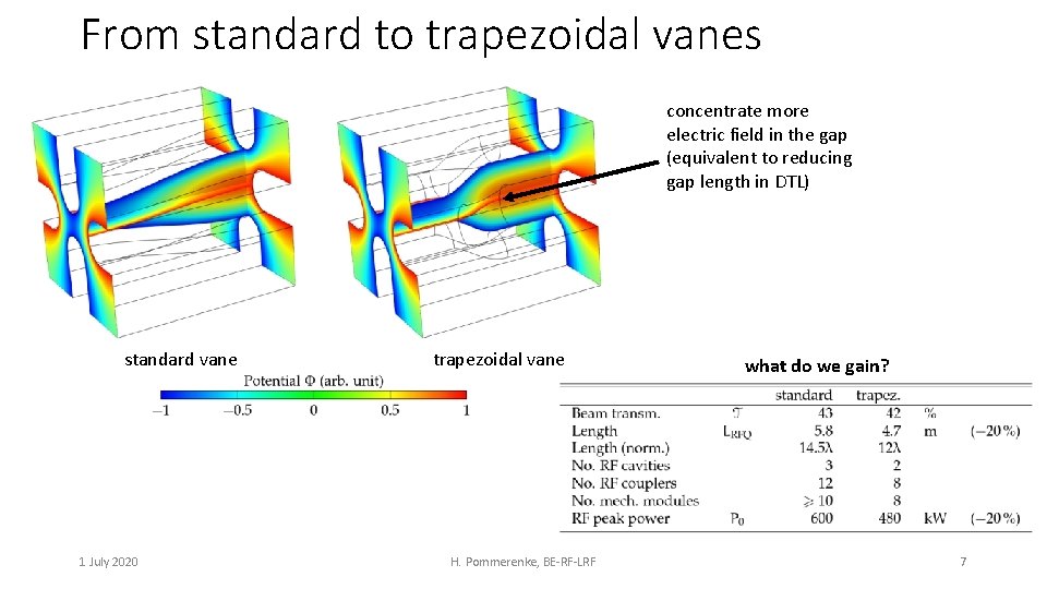
From standard to trapezoidal vanes concentrate more electric field in the gap (equivalent to reducing gap length in DTL) standard vane 1 July 2020 trapezoidal vane H. Pommerenke, BE-RF-LRF what do we gain? 7
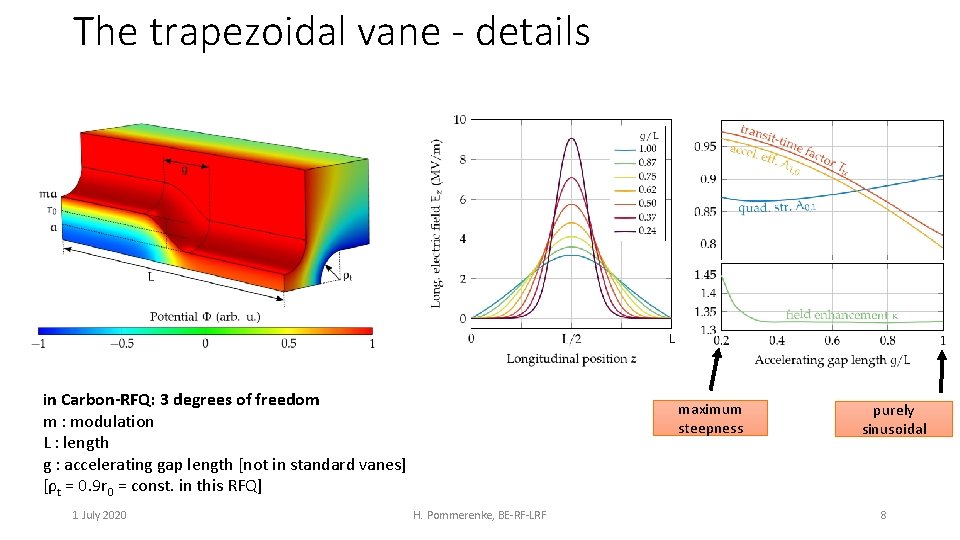
The trapezoidal vane - details in Carbon-RFQ: 3 degrees of freedom m : modulation L : length g : accelerating gap length [not in standard vanes] [ρt = 0. 9 r 0 = const. in this RFQ] 1 July 2020 maximum steepness H. Pommerenke, BE-RF-LRF purely sinusoidal 8
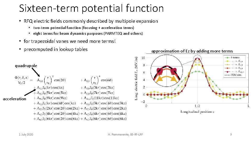
Sixteen-term potential function • RFQ electric fields commonly described by multipole expansion • two-term potential function (focusing + acceleration terms) • eight terms for beam dynamics purposes (PARMTEQ and others) • for trapezoidal vanes we need more terms! • precomputed in lookup tables approximation of Ez by adding more terms quadrupole acceleration 1 July 2020 H. Pommerenke, BE-RF-LRF 9
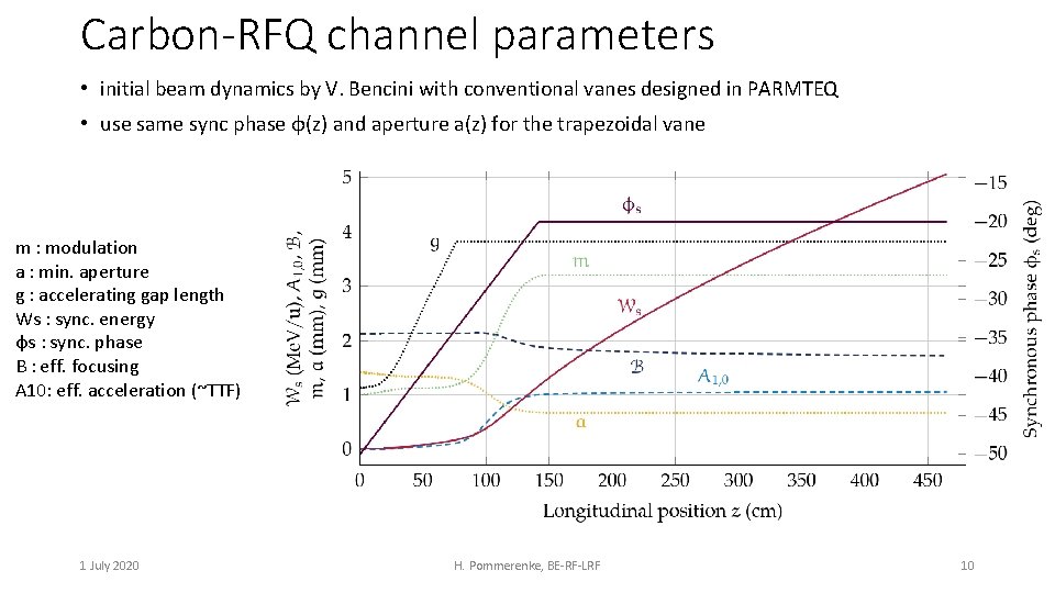
Carbon-RFQ channel parameters • initial beam dynamics by V. Bencini with conventional vanes designed in PARMTEQ • use same sync phase φ(z) and aperture a(z) for the trapezoidal vane m : modulation a : min. aperture g : accelerating gap length Ws : sync. energy φs : sync. phase B : eff. focusing A 10: eff. acceleration (~TTF) 1 July 2020 H. Pommerenke, BE-RF-LRF 10
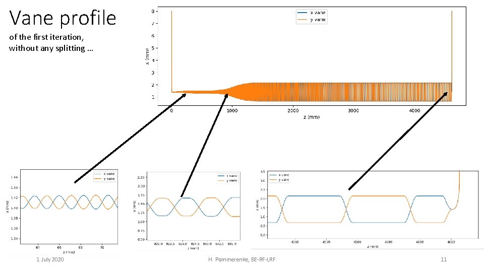
Vane profile of the first iteration, without any splitting … 1 July 2020 H. Pommerenke, BE-RF-LRF 11

Vane CAD models / Potential Φ (k. V) standard vanes trapezoidal vanes 1 July 2020 H. Pommerenke, BE-RF-LRF 12
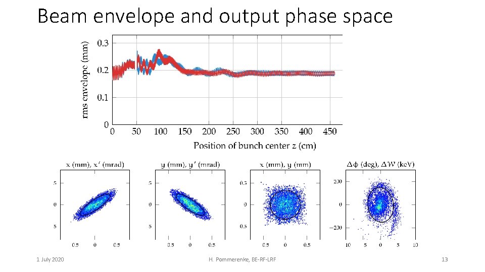
Beam envelope and output phase space 1 July 2020 H. Pommerenke, BE-RF-LRF 13
Part II: Carbon-RFQ RF Design 1 July 2020 H. Pommerenke, BE-RF-LRF 14

2 D cross section • adapted from HF-RFQ / PIXE-RFQ • restrictions: planar back wall for flange aperture, cooling channels • 2 D Q 0*: 7540, 2 D power: 93 k. W/m (*7830, 85 k. W/m for trapezoidal vanes at high energies, due to lower capacitance) 7 deg 46 38 R 0. 4 c = 41. 95 45 deg 8 b = (c+19)/sqrt(2) = 43. 1 plot: magnetic field magnitude 1 July 2020 c is shown for the 2 D cavity. they will be different for each module H. Pommerenke, BE-RF-LRF 15

ideal cavity dimension RFQ is a tapered structure capacitance c b = (c+19 mm)/sqrt(2) each cell requires a slightly different value for c to tune the LC circuit of vane capacitance and cavity inductance we average over each module for only planar surfaces 1 July 2020 H. Pommerenke, BE-RF-LRF 16
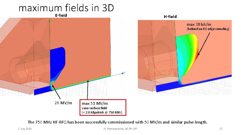
maximum fields in 3 D E-field H-field max 38 k. A/m (behind on R 1 edge rounding) 26 MV/m max 51 MV/m vane surface field (= 2. 0 Kilpatrick @ 750 MHz) The 750 MHz HF-RFQ has been successfully commissioned with 50 MV/m and similar pulse length. 1 July 2020 H. Pommerenke, BE-RF-LRF 17
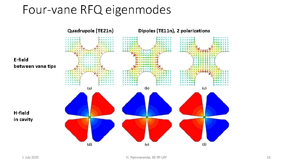
Four-vane RFQ eigenmodes Quadrupole (TE 21 n) Dipoles (TE 11 n), 2 polarizations E-field between vane tips H-field in cavity 1 July 2020 H. Pommerenke, BE-RF-LRF 18
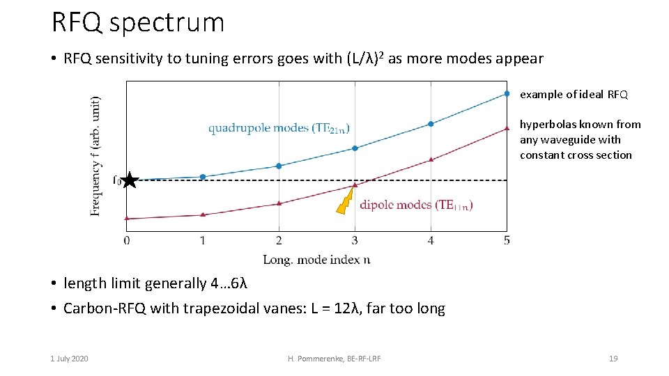
RFQ spectrum • RFQ sensitivity to tuning errors goes with (L/λ)2 as more modes appear example of ideal RFQ hyperbolas known from any waveguide with constant cross section • length limit generally 4… 6λ • Carbon-RFQ with trapezoidal vanes: L = 12λ, far too long 1 July 2020 H. Pommerenke, BE-RF-LRF 19

Splitting the RFQ - spectrum • split RFQ into two fully decoupled cavities, share only vacuum • spectrum of each cavity tuned solely by length adjustment (novel technique that needs no dipole rods, coupling rings etc…) RFQ 1 8. 00 E+08 7. 90 E+08 7. 80 E+08 quadrupoles TE 21 n frequency (Hz) 7. 70 E+08 7. 60 E+08 7. 50 E+08 margin +/- 8 MHz 7. 40 E+08 7. 30 E+08 7. 20 E+08 7. 10 E+08 dipoles TE 11 n 7. 00 E+08 6. 90 E+08 6. 80 E+08 0 1 July 2020 1 2 margin +/- 11 MHz 7. 40 E+08 7. 30 E+08 7. 00 E+08 RFQ 2 8. 00 E+08 3 4 5 mode index = num. long. half-wavelengths 6 0 H. Pommerenke, BE-RF-LRF 1 2 3 4 5 6 mode index = num. long. half-wavelengths 20 7
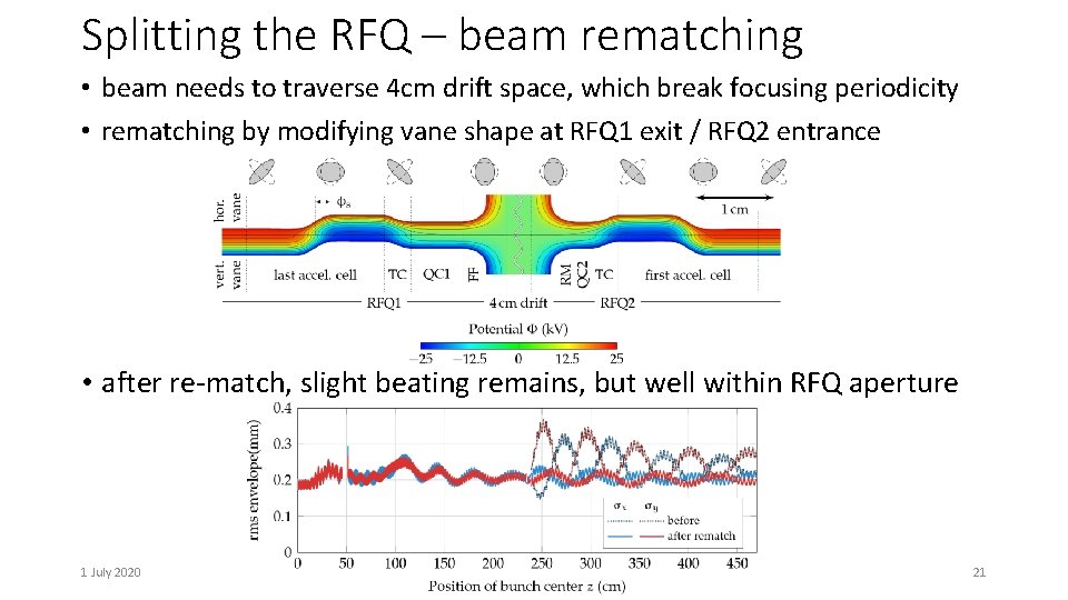
Splitting the RFQ – beam rematching • beam needs to traverse 4 cm drift space, which break focusing periodicity • rematching by modifying vane shape at RFQ 1 exit / RFQ 2 entrance • after re-match, slight beating remains, but well within RFQ aperture 1 July 2020 H. Pommerenke, BE-RF-LRF 21

RFQ auxiliaries • configuration (of both RFQ 1 and RFQ 2) identical to HF-RFQ Auxiliaries Tuners Vacuum pumping ports Couplers RF diagnostic antennas B. Koubek, A. Grudiev, and M. Timmins, “RF measurements and tuning of the 750 MHz radio frequency quadrupole, ” Physical Review Accelerators and Beams 20(8), 2017. 1 July 2020 Auxiliaries Tuner x 4 Vacport x 4 Tuner x 4 Vacport x 2 / Coupler x 2 Tuner x 4 Vacport x 4 Tuner x 4 H. Pommerenke, BE-RF-LRF Number per RFQ 32 (1. 3/λ) 12 4 8 or 16 (? ) RFQ 1 : Z of center (mm) 146. 820 293. 640 440. 460 734. 860 882. 340 1029. 820 1323. 457 1469. 515 1615. 572 1908. 803 2055. 875 2202. 948 RFQ 2 : Z of center (mm) 2536. 022 2682. 015 2828. 008 3118. 155 3262. 210 3406. 265 3696. 967 3843. 515 3990. 062 4282. 465 4428. 220 4573. 975 22
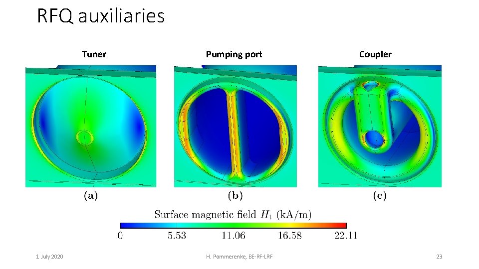
RFQ auxiliaries Tuner 1 July 2020 Pumping port H. Pommerenke, BE-RF-LRF Coupler 23

RF power loss Quantity Carbon-RFQ 1 Carbon-RFQ 2 HF-RFQ Inter-vane voltage 50 50 67. 6 k. V Length 235 230 200 cm Surface losses 244 230 350 k. W Stored energy 343 329 480 m. J <C’> 117 113 100 p. F/m Q 0 6620 6750 6440 Coupling 1. 32 (+32 %) 1. 35 (+35 %) 1. 18 (+18 %) Qex (total) 5000 5475 # couplers 4 4 4 Qex (per coupler) 20000 21900 Power per coupler < 80 < 100 1 July 2020 H. Pommerenke, BE-RF-LRF Segment legend ends ports plain k. W 24
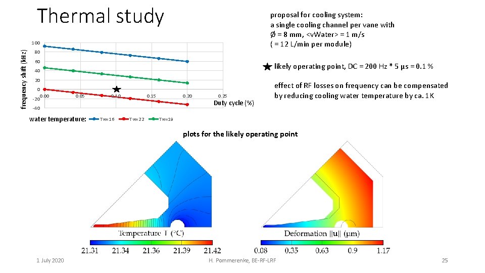
Thermal study proposal for cooling system: a single cooling channel per vane with Ø = 8 mm, <v. Water> = 1 m/s ( = 12 L/min per module) frequency shift (k. Hz) 100 80 60 likely operating point, DC = 200 Hz * 5 µs = 0. 1 % 40 20 0 0. 00 -20 0. 05 0. 10 0. 15 0. 20 -40 water temperature: Tw=16 Tw=22 0. 25 Duty cycle (%) effect of RF losses on frequency can be compensated by reducing cooling water temperature by ca. 1 K Tw=19 plots for the likely operating point 1 July 2020 H. Pommerenke, BE-RF-LRF 25
Part III: Maximum surface fields in RFQs 1 July 2020 H. Pommerenke, BE-RF-LRF 26
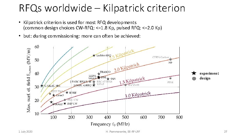
RFQs worldwide – Kilpatrick criterion • Kilpatrick criterion is used for most RFQ developments (common design choices CW-RFQ: <=1. 8 Kp, pulsed RFQ: <=2. 0 Kp) • but: during commissioning: more can often be achieved: experiment design 1 July 2020 H. Pommerenke, BE-RF-LRF 27
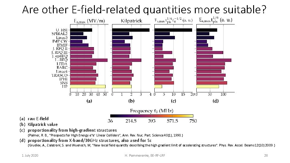
Are other E-field-related quantities more suitable? (a) raw E-field (b) Kilpatrick value (c) proportionality from high-gradient structures (Palmer, R. B. , "Prospects for High Energy e⁺e⁻ Linear Colliders“, Ann. Rev. Nuc. Part. Science 40(1), 1990. ) (d) proportionality from X-band/30 GHz structures, also used for Sc (Grudiev, A. , Calatroni, S. and Wuensch, W, "New local field quantity describing the high gradient limit of accelerating structures". Phys. Rev. Accel. Beams 12(10) 2009. ) 1 July 2020 H. Pommerenke, BE-RF-LRF 28

What about Sc and RF pulsed heating? • Example: proton HF-RFQ: tpls = 20 us, f 0 = 750 MHz Emax on vane tip (2. 0 Kilpatrick) Sc maximum is not on vane, i. e. not in location of breakdowns small hotspot on inter-module gap (2. 2 Kilpatrick) E & H are well-separated in RFQ Sc maximum is located on undercut edge next to dipole rod Hmax on vane undercut edge not critical either, scaled threshold at 20 us: 860 m. W/um² resulting pulsed heating: ΔT = 1. 8 K (critical: 40… 100 K) 1 July 2020 H. Pommerenke, BE-RF-LRF 29
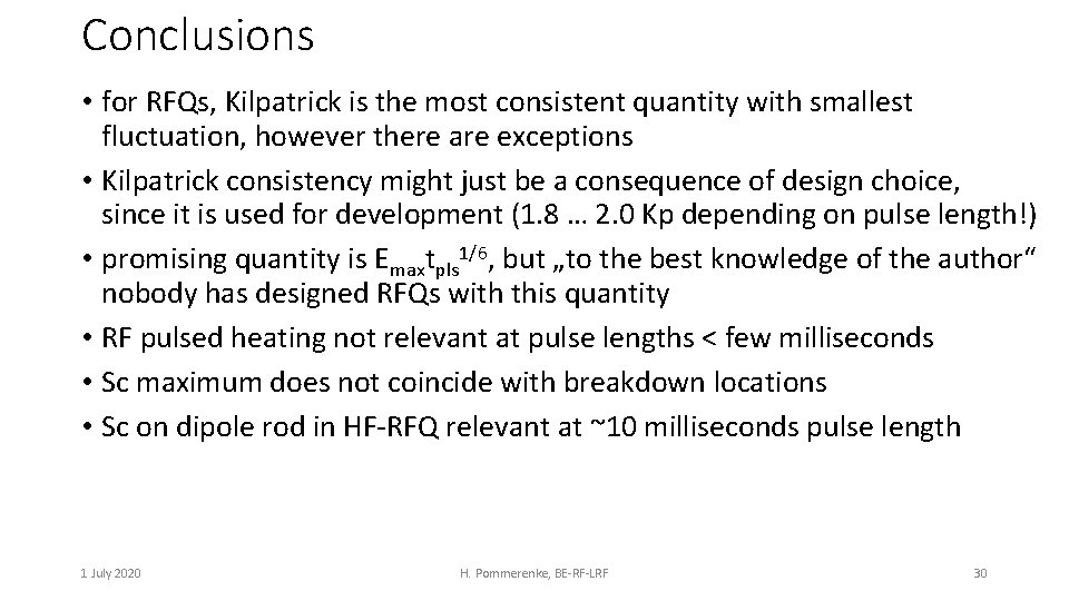
Conclusions • for RFQs, Kilpatrick is the most consistent quantity with smallest fluctuation, however there are exceptions • Kilpatrick consistency might just be a consequence of design choice, since it is used for development (1. 8 … 2. 0 Kp depending on pulse length!) • promising quantity is Emaxtpls 1/6, but „to the best knowledge of the author“ nobody has designed RFQs with this quantity • RF pulsed heating not relevant at pulse lengths < few milliseconds • Sc maximum does not coincide with breakdown locations • Sc on dipole rod in HF-RFQ relevant at ~10 milliseconds pulse length 1 July 2020 H. Pommerenke, BE-RF-LRF 30

Thank you! 1 July 2020 H. Pommerenke, BE-RF-LRF 31
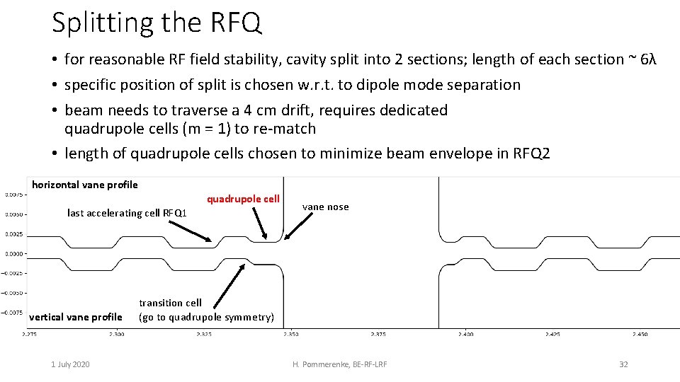
Splitting the RFQ • for reasonable RF field stability, cavity split into 2 sections; length of each section ~ 6λ • specific position of split is chosen w. r. t. to dipole mode separation • beam needs to traverse a 4 cm drift, requires dedicated quadrupole cells (m = 1) to re-match • length of quadrupole cells chosen to minimize beam envelope in RFQ 2 horizontal vane profile quadrupole cell last accelerating cell RFQ 1 vertical vane profile 1 July 2020 vane nose transition cell (go to quadrupole symmetry) H. Pommerenke, BE-RF-LRF 32
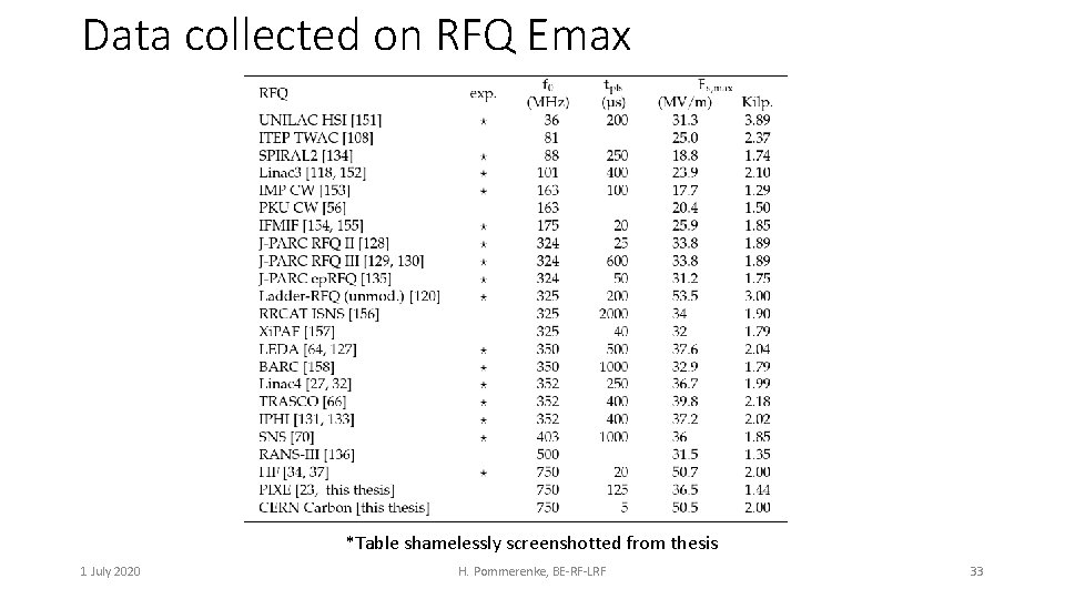
Data collected on RFQ Emax *Table shamelessly screenshotted from thesis 1 July 2020 H. Pommerenke, BE-RF-LRF 33
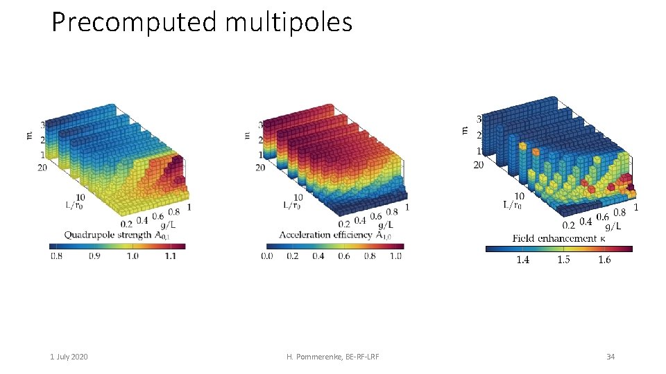
Precomputed multipoles 1 July 2020 H. Pommerenke, BE-RF-LRF 34
- Slides: 34