Design Engineering UNITIII Syllabus CGPA Design Engineering 08

Design Engineering UNIT-III
 Design Engineering (08 Hrs, 16 Marks) a. Design Process b.")
• Syllabus (CGPA) Design Engineering (08 Hrs, 16 Marks) a. Design Process b. Design Concepts c. The Design Model Architectural Design: d. Software Architecture e. Architectural Styles f. Architectural Design User Interface Design: a. Rules b. User Interface Analysis and Design c. Interface Analysis d. Interface Design Steps e. Pattern Based Design f. Design Patterns g. Pattern Based software Design h. Component Level Design patterns i. User Interface Design patterns j. Web. App Design patterns • Introduction to UML Diagrams.

DESIGN WITHIN THE CONTEXT OF SOFTWARE ENGINEERING

• • • software design is the last software engineering action within the modeling activity and sets the stage for construction (code generation and testing). design produces a data/class design, an architectural design, an interface design, and a component design. The data/class design transforms class models into design class realizations and the requisite data structures required to implement the software. The objects and relationships defined in the CRC diagram and the detailed data content depicted by class attributes and other notation provide the basis for the data design action. architectural design defines the relationship between major structural elements of the software. architectural design representation—the framework of a computer-based system—is derived from the requirements model.

• interface design describes how the software communicates with system. • interface implies a flow of information (e. g. , data and/or control) and a specific type of behavior. • component-level design transforms structural elements of the software architecture into a procedural description of software components • Design provides you with representations of software that can be assessed for quality. • Design is the only way that you can accurately translate stakeholder‘s requirements into a finished software product or system. • Software design serves as the foundation for all the software engineering and software support activities that follow

THE DESIGN PROCESS Ø Software Quality Guidelines and Attributes Quality Guidelines -Mc. Glaughlin suggests three characteristics that serve as a guide for the evaluation of a good design: • The design must implement all of the explicit requirements contained in the requirements model, and it must accommodate all of the implicit requirements desired by stakeholders. • The design must be a readable, understandable guide for those who generate code and for those who test and subsequently support the software. • The design should provide a complete picture of the software, addressing the data, functional, and behavioural domains from an implementation perspective. • A design should exhibit an architecture that (1) has been created using recognizable architectural styles or patterns, (2) is composed of components that exhibit good design characteristics , and (3) can be implemented in an evolutionary fashion, thereby facilitating implementation and testing.

• A design should be modular; • A design should contain representations of data, architecture, interfaces, and components. • A design should lead to components that exhibit independent functional characteristics. • A design should lead to interfaces that reduce the complexity of connections between components and with the external environment. • A design should be derived using a repeatable method that is driven by information obtained during software requirements analysis. • A design should be represented using a notation that effectively communicates its meaning.

Quality Attributes -FURPS—functionality, usability, reliability, performance, and supportability ü Functionality • evaluating the feature set and capabilities of the program, the generality of the functions that are delivered, and the security of the overall system. ü Usability • assessed by considering human overall aesthetics, consistency, and documentation. ü Reliability • evaluated by measuring the frequency and severity of failure, the accuracy of output results, the mean-time-to-failure (MTTF), the ability to recover from failure, and the predictability of the program. ü Performance • measured by considering processing speed, response time, resource consumption, throughput, and efficiency. ü Supportability • ability to extend the program (extensibility), adaptability, serviceability

DESIGN CONCEPTS q The Evolution of Software Design - Early design work on modular programs and methods for refining software structures in a topdown manner. - Procedural aspects of design definition evolved into a philosophy called structured programming. - methods for the translation of data flow or data structure into a design definition. - Newer design proposed an object-oriented approach. - More recent emphasis on software architecture and the design patterns that can be used to implement software architectures and lower levels of design abstractions. - Growing emphasis on aspect-oriented methods, Modeldriven development and test-driven development

§ Abstraction - At the highest level of abstraction, a solution is stated in broad terms using the language of the problem environment. At lower levels of abstraction, a more detailed description of the solution is provided. ü procedural abstraction: refers to a sequence of instructions that have a specific and limited function -(e. g. , walk to the door, reach out and grasp knob, turn knob and pull door, step away from moving door, etc. ). ü data abstraction: is a named collection of data that describes a data object. (e. g. , door type, swing direction, opening mechanism, weight, dimensions)

§ Architecture - Software architecture ―the overall structure of the software and the ways in which that structure provides conceptual integrity for a system. - architecture is the structure or organization of program components (modules), the manner in which these components interact, and the structure of data that are used by the components - Structural properties: defines the components of a system (e. g. , modules, objects, filters) and the manner in which those components are packaged and interact with one another. ü Extra-functional properties: address how the design architecture achieves requirements for performance, capacity, reliability, security, adaptability, and other system characteristics. ü Families of related systems: design should have the ability to reuse architectural building blocks.

- Structural models represent architecture as an organized collection of program components. - Framework models increase the level of design abstraction by attempting to identify repeatable architectural design frameworks that are encountered in similar types of applications. - Dynamic models address the behavioral aspects of the program architecture, indicating how the structure or system configuration may change as a function of external events. - Process models focus on the design of the business or technical process that the system must accommodate. - functional models can be used to represent the functional hierarchy of a system. § Patterns • describes a design structure that solves a particular design problem within a specific context and amid ―”forces” that may have an impact on the manner in which the pattern is applied and used. • The intent of each design pattern is to provide a description that enables a designer to determine (1) whether the pattern is applicable to the current work, (2) whether the pattern can be reused (hence, saving design time), and (3) whether the pattern can serve as a guide for developing a similar, but functionally or structurally different pattern

§ Separation of Concerns -It is a design concept that suggests that any complex problem can be more easily handled if it is subdivided into pieces that can each be solved and/or optimized independently. - A concern is a feature or behaviour that is specified as part of the requirements model for the software. - By separating concerns into smaller, and therefore manageable pieces, a problem takes less effort and time to solve

DESIGN CONCEPTS continued…. . § Modularity - - Software is divided into separately named and addressable components, sometimes called modules, that are integrated to satisfy problem requirements. Referring to Figure , the effort (cost) to develop an individual software module does decrease as the total number of modules increases. Given the same set of requirements, more modules means smaller individual size. as the number of modules grows, the effort (cost) associated with integrating the modules also grows. There is a number, M, of modules that would result in minimum development cost, but we do not have the necessary sophistication to predict M with assurance.

§ Information Hiding • modules should be specified and designed so that information (algorithms and data) contained within a module is inaccessible to other modules that have no need for such information. • Hiding implies that effective modularity can be achieved by defining a set of independent modules that communicate with one another only that information necessary to achieve software function § Functional Independence - design software so that each module addresses a specific subset of requirements and has a simple interface when viewed from other parts of the program structure. - functional independence is a key to good design, and design is the key to software quality - Independence is assessed using two qualitative criteria: cohesion and coupling.

ü Cohesion is an indication of the relative functional strength of a module. Coupling is an indication of the relative interdependence among modules. ü cohesive module performs a single task, requiring little interaction with other components in other parts of a program. Stated simply, a cohesive module should (ideally) do just one thing ü Coupling is an indication of interconnection among modules in a software structure. Coupling depends on the interface complexity between modules, § Refinement - top-down design strategy - A hierarchy is developed by decomposing a macroscopic statement of function (a procedural abstraction) in a stepwise fashion until programming language statements are reached. Refinement is actually a process of elaboration - elaborate on the original statement, providing more and more detail as each successive refinement (elaboration) occurs. Abstraction and refinement are complementary concepts. - Refinement helps to reveal low-level details

§ Aspects -a requirements model can be organized in a way that allows you to isolate each concern (requirement) so that it can be considered independently. - aspect is a representation of a crosscutting concern. - It is important to identify aspects so that the design can properly accommodate them as refinement and modularization occur. - an aspect is implemented as a separate module (component) rather than as software fragments that are scattered‖. - design architecture should support a mechanism for defining an aspect—a module that enables the concern to be implemented across all other concerns that it crosscuts. § Refactoring - - refactoring is a reorganization technique that simplifies the design (or code) of a component without changing its function or behavior. Refactoring is the process of changing a software system in such a way that it does not alter the external behavior of the code [design] yet improves its internal structure. When software is refactored, the existing design is examined for redundancy, unused design elements, inefficient or unnecessary algorithms, poorly constructed or inappropriate data structures, or any other design failure ‖

§ Object-Oriented Design Concepts - OO design concepts such as classes and objects, inheritance, messages, and polymorphism, among others. § Design Classes - define a set of design classes that refine the analysis classes by providing design detail that will • • • enable the classes to be implemented, and implement a software infrastructure that supports the business solution. Five different types of design classes, each representing a different layer of the design architecture, can be developed User interface classes define all abstractions that are necessary for human computer interaction (HCI). In many cases, HCI occurs within the context of a metaphor (e. g. , a checkbook, an order form, a fax machine), and the design classes for the interface may be visual representations of the elements of the metaphor. Business domain classes : The classes identify the attributes and services (methods) that are required to implement some element of the business domain. Process classes implement lower-level business abstractions required to fully manage the business domain classes. Persistent classes represent data stores (e. g. , a database) that will persist beyond the execution of the software. System classes implement software management and control functions that enable the system to operate and communicate within its computing environment and with the outside world.

THE DESIGN MODEL

• The process dimension indicates the evolution of the design model as design tasks are executed as part of the software process. • The abstraction dimension represents the level of detail as each element of the analysis model is transformed into a design equivalent and then refined iteratively. • Referring to Figure, the dashed line indicates the boundary between the analysis and design models.

THE DESIGN MODEL Ø Data Design Elements -data design (sometimes referred to as data architecting) creates a model of - data and/or information that is represented at a high level of abstraction. data model is then refined into progressively more implementation-specific representations that can be processed by the computer-based system. Ø Architectural Design Elements -Architectural design elements give us an overall view of the software. - derived from three sources: (1) information about the application domain; (2) specific requirements model elements such as data flow diagrams or analysis classes, their relationships and (3) the availability of architectural styles and patterns - The architectural design element is depicted as a set of interconnected subsystems

Ø Interface Design Elements - The interface design elements for software depict information flows into and out of the system and how it is communicated among the components defined as part of the architecture. - three important elements of interface design: (1) the user interface (UI); (2) external interfaces to other systems, devices, networks, or other producers or consumers of information (3) internal interfaces between various design components. - an interface is a set of operations that describes some part of the behavior of a class and provides access to these operations. Ø Component-Level Design Elements - component-level design defines data structures for all local data objects and algorithmic detail for all processing that occurs within a component and an interface that allows access to all component operations (behaviors).

Ø Deployment-Level Design Elements - indicate how software functionality and subsystems will be allocated within the physical computing environment that will support the software. - deployment diagram shows the computing environment but does not explicitly indicate configuration details

ARCHITECTURAL DESIGN

ARCHITECTURAL STYLES • The software that is built for computer-based systems exhibits one of many architectural styles. Each style describes a system category that encompasses (1) a set of components (e. g. , a database, computational modules) that perform a function required by a system; (2) a set of connectors that enable ―communication, coordination and cooperation‖ among components; (3) constraints that define how components can be integrated to form the system; (4) semantic models that enable a designer to understand the overall properties of a system by analyzing the known properties of its constituent parts. - An architectural style is a transformation that is imposed on the design of an entire system. - The intent is to establish a structure for all components of the system

Ø A Brief Taxonomy of Architectural Styles 1. Data-centered architectures - - A data store (e. g. , a file or database) resides at the center of this architecture and is accessed frequently by other components that update, add, delete, or otherwise modify data within the store. Figure illustrates a typical data-centered style. Client software accesses a central repository. data repository is passive. That is, client software accesses the data independent of any changes to the data or the actions of other client software Data-centered architectures promote integrability. That is, existing components can be changed and new client components added to the architecture without concern about other clients

2. Data-flow architectures • architecture is applied when input data are to be transformed through a series of computational or manipulative components into output data. • A pipe-and-filter pattern (Figure 9. 2) has a set of components, called filters, connected by pipes that transmit data from one component to the next. • Each filter works independently of those components upstream and downstream, is designed to expect data input of a certain form, and produces data output (to the next filter) of a specified form. • the filter does not require knowledge of the workings of its neighboring filters.

ARCHITECTURAL STYLES. . 3. Call and return architectures • • - - This architectural style enables you to achieve a program structure that is relatively easy to modify and scale. A number of substyles exist within this category: Main program/subprogram architectures. This classic program structure decomposes function into a control hierarchy where a ―main program invokes a number of program components that in turn may invoke still other components. Figure 9. 3 illustrates an architecture of this type. Remote procedure call architectures. The components of a main program/subprogram architecture are distributed across multiple computers on a network.

4. Object-oriented architectures • The components of a system encapsulate data and the operations that must be applied to manipulate the data. • Communication and coordination between components are accomplished via message passing. 5. Layered architectures • A number of different layers are defined, each accomplishing operations that progressively become closer to the machine instruction set. • At the outer layer, components service user interface operations. • At the inner layer, components perform operating system interfacing. • Intermediate layers provide utility services and application software functions. • the architectural style and/or combination of patterns that best fits those characteristics and constraints can be chosen. • more than one pattern might be appropriate and alternative architectural styles can be designed and evaluated

ARCHITECTURAL STYLES

§ Architectural Patterns - Architectural patterns address an applicationspecific problem within a specific context and under a set of limitations and constraints. - The pattern proposes an architectural solution that can serve as the basis for architectural design.

§ Organization and Refinement -The following questions provide insight into an architectural style: 1. Control: • How is control managed within the architecture? • Does a distinct control hierarchy exist, and if so, what is the role of components within this control hierarchy? • How do components transfer control within the system? • How is control shared among components? • What is the control topology (i. e. , the geometric form that the control takes)? • Is control synchronized or do components operate asynchronously?

2. Data. • How are data communicated between components? • Is the flow of data continuous, or are data objects passed to the system sporadically? • What is the mode of data transfer (i. e. , are data passed from one component to another or are data available globally to be shared among system components)? • Do data components (e. g. , a blackboard or repository) exist, and if so, • what is their role? • How do functional components interact with data components? • Are data components passive or active (i. e. , does the data component actively interact with other components in the system)? • How do data and control interact within the system? • These questions provide the designer with an early assessment of design quality and lay the foundation for more detailed analysis of the architecture.

ARCHITECTURAL DESIGN Ø Representing the System in Context

• At the architectural design level, a software architect uses an architectural context diagram (ACD) to model the manner in which software interacts with entities external to its boundaries. • The generic structure of the architectural context diagram is illustrated in Figure 9. 5. -Superordinate systems—those systems that use the target system as part of some higher-level processing scheme. -Subordinate systems—those systems that are used by the target system and provide data or processing that are necessary to complete target system functionality. - Peer-level systems—those systems that interact on a peer-to-peer basis (i. e. , information is either produced or consumed by the peers and the target system. -Actors—entities (people, devices) that interact with the target system by producing or consuming information that is necessary for requisite processing. Each of these external entities communicates with the target system through an interface (the small shaded rectangles).

ARCHITECTURAL DESIGN Ø Defining Archetypes • An archetype is a class or pattern that represents a core abstraction that is critical to the design of an architecture for the target system. • a relatively small set of archetypes is required to design even relatively complex systems. • The target system architecture is composed of these archetypes, which represent stable elements of the architecture but may be instantiated many different ways based on the behavior of the system.

ARCHITECTURAL DESIGN Ø Refining the Architecture into Components • • • the application domain is one source for the derivation and refinement of components. Another source is the infrastructure domain. The architecture must accommodate many infrastructure components that enable application components but have no business connection to the application domain. For example, memory management components, communication components, database components, and task management components are often integrated into the software architecture. The interfaces depicted in the architecture context diagram imply one or more specialized components that process the data that flows across the interface. In some cases (e. g. , a graphical user interface), a complete subsystem architecture with many components must be designed.

THE GOLDEN RULES 1. Place the User in Control 1. Define interaction modes in a way that does not force a user into unnecessary or undesired actions 2. Provide for flexible interaction 3. Allow user interaction to be interruptible and undoable 4. Streamline interaction as skill levels advance and allow the interaction to be customized 5. Hide technical internals from the casual user 6. Design for direct interaction with objects that appear on the screen 2. Reduce the User’s Memory Load 1. 2. 3. 4. 5. Reduce demand on short-term memory Establish meaningful defaults Define shortcuts that are intuitive The visual layout of the interface should be based on a real-world metaphor Disclose information in a progressive fashion

USER INTERFACE DESIGN

THE GOLDEN RULES 3. Make the Interface Consistent 1. Allow the user to put the current task into a meaningful context 2. Maintain consistency across a family of applications 3. If past interactive models have created user expectations, do not make changes unless there is a compelling reason to do so

USER INTERFACE ANALYSIS AND DESIGN Interface Analysis and Design Models • user model - establishes the profile of end users of the system. In his introductory column on user-centric design‖. users can be categorized as: a. Novices: - No syntactic knowledge of the system and little semantic knowledge of the application or computer usage in general. b. Knowledgeable, intermittent users. : - Reasonable semantic knowledge of the application. c. acknowledgeable, frequent users. - Good semantic and syntactic knowledge that often leads to the ―power-user syndrome ; that is, individuals who look for shortcuts and abbreviated modes of interaction.

• design model - developed to accommodate the information contained in the user model • mental model or the system perception -user‘s mental model (system perception) is the image of the system that end users carry in their heads • implementation model - combines the outward manifestation of the computer based system (the look and feel of the interface), coupled with all supporting information (books, manuals, videotapes, help files) that describes interface syntax and semantics.

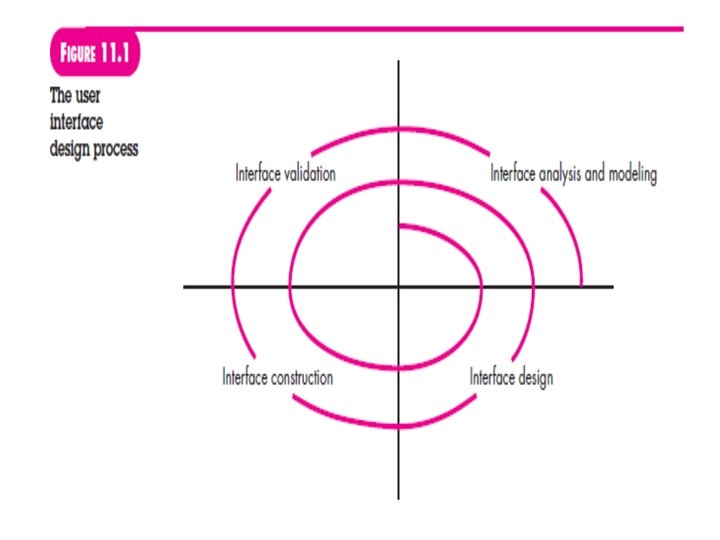
USER INTERFACE ANALYSIS AND DESIGN • The Process -The analysis and design process for user interfaces is iterative and can be represented using a spiral model. -user interface analysis and design process begins at the interior of the spiral and encompasses four distinct framework activities (1) interface analysis and modeling, (2) interface design, (3) interface construction, and (4) interface validation. -The spiral shown in Figure 11. 1 implies that each of these tasks will occur more than once, with each pass around the spiral representing additional elaboration of requirements and the resultant design. - the construction activity involves prototyping—the only practical way to validate what has been designed

- INTERFACE ANALYSIS In the case of user interface design, understanding the problem means understanding (1) the people (end users) who will interact with the system through the interface, (2) the tasks that end users must perform to do their work, (3) the content that is presented as part of the interface, (4) the environment in which these tasks will be conducted. User Analysis ü User Interviews ü Sales input ü Marketing input ü Support input

following set of questions will help you to better understand the users of a system: • Are users trained professionals, technicians, clerical, or manufacturing workers? • What level of formal education does the average user have? • Are the users capable of learning from written materials or have they expressed a desire for classroom training? • Are users expert typists or keyboard phobic? • What is the age range of the user community? • Will the users be represented predominately by one gender? • How are users compensated for the work they perform? • Do users work normal office hours or do they work until the job is done? • Is the software to be an integral part of the work users do or will it be used only occasionally? • What is the primary spoken language among users? • What are the consequences if a user makes a mistake using the system? • Are users experts in the subject matter that is addressed by the system? • Do users want to know about the technology that sits behind the interface?

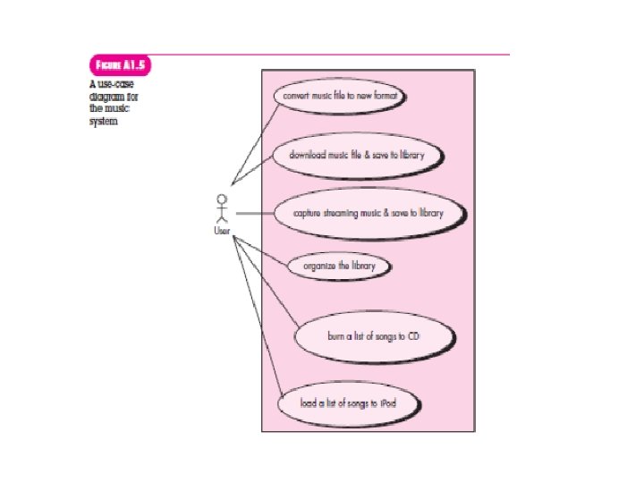
Task Analysis and Modeling goal of task analysis is to answer the following questions: • What work will the user perform in specific circumstances? • What tasks and subtasks will be performed as the user does the work? • What specific problem domain objects will the user manipulate as work is performed? • What is the sequence of work tasks—the workflow? • What is the hierarchy of tasks? techniques are applied to the user interface : - ü Use cases - use case is developed to show an end user performs some specific work-related task ü Task elaboration ü Object elaboration - objects can be categorized into classes Attributes of each class are defined, and an evaluation of the actions applied to each object provide a list of operations.

ü Workflow analysis - technique allows you to understand how a work process is completed when several people (and roles) are involved ü Hierarchical representation - Once workflow has been established, a task hierarchy can be defined for each user type. hierarchy is derived by a stepwise elaboration of each task identified for the user Analysis of Display Content • display content can range from character-based reports (e. g. , a spreadsheet), graphical displays (e. g. , a histogram, a 3 -D model, a picture of a person), or specialized information (e. g. , audio or video files).

questions that are asked answered are: • Are different types of data assigned to consistent geographic locations on the screen (e. g. , photos always appear in the upper right-hand corner)? • Can the user customize the screen location for content? • Is proper on-screen identification assigned to all content? • If a large report is to be presented, how should it be partitioned for ease of understanding? • Will mechanisms be available for moving directly to summary information for large collections of data? • Will graphical output be scaled to fit within the bounds of the display device that is used? • How will color be used to enhance understanding? • How will error messages and warnings be presented to the user? • The answers to these (and other) questions will help you to establish requirements for content presentation. § Analysis of the Work Environment

PATTERN-BASED DESIGN

DESIGN PATTERNS effective design pattern in the following way: • It solves a problem: Patterns capture solutions, not just abstract principles or strategies. • It is a proven concept: Patterns capture solutions with a track record, not theories or speculation. • The solution isn’t obvious: Many problem-solving techniques (such as software design paradigms or methods) try to derive solutions from first principles. The best patterns generate a solution to a problem indirectly—a necessary approach for the most difficult problems of design. • It describes a relationship: Patterns don‘t just describe modules, but describe deeper system structures and mechanisms. • The pattern has a significant human component (minimize human intervention). All software serves human comfort or quality of life; the best patterns explicitly appeal to aesthetics and utility.

Kinds of Patterns • identify a pattern that describes an important and repeatable aspect of a system and that provides us with a way to build that aspect within a system of forces that are unique to a given context. ü Architectural patterns describe design problems that are solved using a structural approach. ü Data patterns describe recurring data-oriented problems and the data modeling solutions that can be used to solve them. ü Component patterns address problems associated with the development of subsystems and components, the manner in which they communicate with one another, and their placement within a larger architecture. ü Interface design patterns describe common user interface problems and their solution that includes the specific characteristics of end users. ü Web. App patterns address a problem set that is encountered when building Web. Apps.

ü Creational patterns focus on the “creation, composition, and representation” of objects. ü Structural patterns focus on problems and solutions associated with how classes and objects are organized and integrated to build a larger structure. ü Behavioral patterns address problems associated with the assignment of responsibility between objects and the manner in which communication is effected between objects. Frameworks -In some cases it may be necessary to provide an implementationspecific skeletal infrastructure, called a framework, for design work. That is, you can select a “reusable miniarchitecture that provides the generic structure and behavior for a family of software

differences between design patterns and frameworks in the following manner: 1. Design patterns are more abstract than frameworks. Frameworks can be embodied in code, but only examples of patterns can be embodied in code. A strength of frameworks is that they can be written down in programming languages and not only studied but executed and reused directly. 2. Design patterns are smaller architectural elements than frameworks. A typical framework contains several design patterns but the reverse is never true. 3. Design patterns are less specialized than frameworks. Frameworks always have a particular application domain. In contrast, design patterns can be used in nearly any kind of application. While more specialized design patterns are certainly possible, even these wouldn‘t dictate an application architecture.

§ Describing a Pattern - To communicate information unambiguously, a standard form or template for pattern descriptions is required The names of design patterns should be chosen with care. One of the key technical problems in pattern-based design is the inability to find existing patterns when hundreds or thousands of candidate patterns exist. The search for the ―right‖ pattern is aided immeasurably by a meaningful pattern name. A pattern template provides a standardized means for describing a design pattern. Each of the template entries represents characteristics of the design pattern that can be searched (e. g. , via a database) so that the appropriate pattern can be found.

§ Pattern Languages and Repositories • language has a syntax and semantics that are used to communicate ideas or procedural instructions in an effective manner. • When the term language is used in the context of design patterns, it takes on a slightly different meaning. • A pattern language encompasses a collection of patterns, each described using a standardized template and interrelated to show these patterns collaborate to solve problems across an application domain. • In a natural language, words are organized into sentences that impart meaning. The structure of sentences is described by the language‘s syntax. • In a pattern language, design patterns are organized in a way that provides a ―structured method of describing good design practices within a particular domain

§ PATTERN-BASED SOFTWARE DESIGN -Applying pattern based design to software development promises the same benefits to software as it does to industrial technology: predictability, risk mitigation, and increased productivity. Ø Pattern-Based Design in Context - A software designer begins with a requirements model (either explicit or implied) that presents an abstract representation of the system. - The requirements model describes the problem set, establishes the context, and identifies the system of forces Ø Thinking in Patterns Approach that enables a designer to think in patterns: 1. Be sure you understand the big picture—the context in which the software to be built resides. The requirements model should communicate this to you. 2. Examining the big picture, extract the patterns that are present at that level of abstraction.

3. Begin your design with ―big picture‖ patterns that establish a context or skeleton for further design work. 4. Work inward from the context‖ looking for patterns at lower levels of abstraction that contribute to the design solution. 5. Repeat steps 1 to 4 until the complete design is fleshed out. 6. Refine the design by adapting each pattern to the specifics of the software you‘re trying to build.

Ø Design Tasks following design tasks are applied when a pattern-based design philosophy is used: 1. Examine the requirements model and develop a problem hierarchy. 2. Determine if a reliable pattern language has been developed for the problem domain. 3. Beginning with a broad problem, determine whether one or more architectural patterns is available for it. 4. Using the collaborations provided for the architectural pattern, examine subsystem or component-level problems and search for appropriate patterns to address them. 5. Repeat steps 2 through 5 until all broad problems have been addressed. 6. If user interface design problems have been isolated (this is almost always the case), search the many user interface design pattern repositories for appropriate patterns. 7. Regardless of its level of abstraction, if a pattern language and/or patterns repository or individual pattern shows promise, compare the problem to be solved against the existing pattern(s) presented. 8. Be certain to refine the design as it is derived from patterns using design quality criteria as a guide.

Ø Building a Pattern-Organizing Table -A pattern-organizing table can be implemented as a spreadsheet model using the form shown in the figure Ø Common Design Mistakes -not enough time has been spent to understand the underlying problem and its context and forces, and as a consequence, - you select a pattern that looks right but is inappropriate for the solution required. Once the wrong pattern is selected, you refuse to see your error and force-fit the pattern. - Sometimes a pattern is applied too literally and the required adaptations for your problem space are not implemented.

Ø COMPONENT-LEVEL DESIGN PATTERNS - provide you with proven solutions that address one or more subproblems extracted from the requirements model. Ø USER INTERFACE DESIGN PATTERNS - Hundreds of user interface (UI) patterns have been proposed in recent years

WEBAPP DESIGN PATTERNS • Design Focus ü Information architecture patterns relate to the overall structure of the information space, and the ways in which users will interact with the information. ü Navigation patterns define navigation link structures, such as hierarchies, rings, tours, and so on. ü Interaction patterns contribute to the design of the user interface. Patterns in this category address how the interface informs the user of the consequences of a specific action, how a user expands content based on usage context and user desires, how to best describe the destination that is implied by a link, how to inform the user about the status of an ongoing interaction, and interface-related issues.

WEBAPP DESIGN PATTERNS ü Presentation patterns in this category address how to organize user interface control functions for better usability, how to show the relationship between an interface action and the content objects it affects, and how to establish effective content hierarchies. ü Functional patterns define the workflows, behaviors, processing, communication, and other algorithmic elements within a Web. App. Design Granularity ü Architectural patterns. This level of abstraction will typically relate to patterns that define the overall structure of the Web. App, indicate the relationships among different components or increments, and define the rules for specifying relationships among the elements (pages, packages, components, subsystems) of the architecture.

WEBAPP DESIGN PATTERNS ü Design patterns. These address a specific element of the design such as an aggregation of components to solve some design problem, relationships among elements on a page, or the mechanisms for effecting component-to component communication. ü Component patterns. This level of abstraction relates to individual small scale elements of a Web. App. Examples include individual interaction elements (e. g. , radio buttons), navigation items (e. g. , how might you format links? ) or functional elements (e. g. , specific algorithms).
 is ―a standard")
AN INTRODUCTION TO UML • • The Unified Modeling Language (UML) is ―a standard language for writing software blueprints. UML may be used to visualize, specify, construct, and document the artifacts of a software-intensive system‖. In otherwords, just as building architects create blueprints to be used by a construction company, software architects create UML diagrams to help software developers build the software. If you understand the vocabulary of UML (the diagrams‘ pictorial elements and their meanings), you can much more easily understand specify a system and explain the design of that system to others. Grady Booch, Jim Rumbaugh, and Ivar Jacobson developed UML in the mid- 1990 s with much feedback from the software development community. UML merged a number of competing modeling notations that were in use by the software industry at the time. In 1997, UML 1. 0 was submitted to the Object Management Group, a nonprofit consortium involved in maintaining specifications for use by the computer industry. UML 1. 0 was revised to UML 1. 1. The current standard is UML 2. 0 and is now an ISO standard. UML 2. 0 provides 13 different diagrams for use in software modeling

Ø CLASS DIAGRAMS • To model classes, including their attributes, operations, and their relationships and associations with other classes, UML provides a class diagram. • A class diagram provides a static or structural view of a system. It does not show the dynamic nature of the communications between the objects of the classes in the diagram. • The main elements of a class diagram are boxes, which are the icons used to represent classes and interfaces. • Each box is divided into horizontal parts. The top part contains the name of the class. The middle section lists the attributes of the class. An attribute refers to something that an object of that class knows or can provide all the time. Attributes are usually implemented as fields of the class

Ø DEPLOYMENT DIAGRAMS • A UML deployment diagram focuses on the structure of a software system and is useful for showing the physical distribution of a software system among hardware platforms and execution environments Ø USE-CASE DIAGRAMS • Use cases and the UML use-case diagram help you determine the functionality and features of the software from the user‘s perspective

Ø SEQUENCE DIAGRAMS - a sequence diagram is used to show the dynamic communications between objects during execution of a task. - It shows the temporal order in which messages are sent between the objects to accomplish that task. - use a sequence diagram to show the interactions in one use case or in one scenario of a software system.

Ø COMMUNICATION DIAGRAMS • The UML communication diagram (called a ―collaboration diagram‖ in UML 1. X) provides another indication of the temporal order of the communications but emphasizes the relationships among the objects and classes instead of the temporal order.

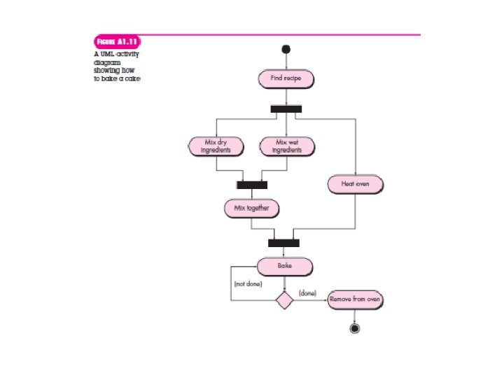
Ø ACTIVITY DIAGRAMS • • • A UML activity diagram depicts the dynamic behavior of a system or part of a system through the flow of control between actions that the system performs. It is similar to a flowchart except that an activity diagram can show concurrent flows. The main component of an activity diagram is an action node, represented by a rounded rectangle, which corresponds to a task performed by the software system. Arrows from one action node to another indicate the flow of control. That is, an arrow between two action nodes means that after the first action is complete the second action begins. A solid black dot forms the initial node that indicates the starting point of the activity. A black dot surrounded by a black circle is the final node indicating the end of the activity. A fork represents the separation of activities into two or more concurrent activities. It is drawn as a horizontal black bar with one arrow pointing to it and two or more arrows pointing out from it. Each outgoing arrow represents a flow of control that can be executed concurrently with the flows corresponding to the other outgoing arrows.

Ø STATE DIAGRAMS • The behavior of an object at a particular point in time often depends on the state of the object, that is, the values of its variables at that time. • A UML state diagram models an object‘s states, the actions that are performed depending on those states, and the transitions between the states of the object.


- Slides: 75