Design Development and Construction of a Magnetohydrodynamic Cocktail


 • Uses magnetohydrodynamics •")

 • Nd.")
 • Eddy")


 and weight (~20 lb) of spinner assembly")


 • Internal PID")


- Slides: 23
Design, Development and Construction of a Magnetohydrodynamic Cocktail Stirrer Carlos Gross Jones
Problem • Density- and temperature-driven separation in cocktails
Existing Solutions Spoon, Swizzle Stick Lab Stir Plate • Boring • Uses magnetic “pill” • Possibility of cross-contamination • Pill must be retrieved • Still pretty boring
Proposal: Contactless Cocktail Stirrer • Truly contactless (no magnetic “pill”) • Uses magnetohydrodynamics • Electrical and magnetic interactions with conductive fluid
Magnetohydrodynamics • Well studied in marine propulsion • Simplest applications is Lorentz-force drive
Early Efforts: 2013 • Used direct insertion of current (electrodes in drink) • Nd. Fe. B permanent magnet • Advantages: • Simple • Provides good pumping • Disadvantages: • Electrolysis of drink • Electrically-driven erosion of electrodes
Current effort: Magnetodynamic Coupling • Changing magnetic field induces currents (Faraday’s Law) • Eddy currents interact with original magnetic field (Lorentz force) • Commonly used in contactless braking systems
Challenges • Root problem: cocktails are much less conductive than copper • Requires large d. B/dt to create significant force • Increase field strength, rate of change, or both • Must meet budget and space constraints • No superconductors, custom magnets, etc. • Must fit in my living room
Magnet Selection • Supermagnet from United Nuclear • 3” dia. , 1” thick • Nd. Fe. B 45
Magnetostatic Analysis: FEMM • Used to characterize static field • Quadrupole arrangement provides stronger (maximum) field than dipole • 1018 steel shunts to provide good return path • Maximum of 0. 418 T in glass
Magnetodynamic Analysis: Ansys Maxwell • Quadrupole assembly spun at 3600 RPM • Seawater used as conductivity baseline • Generates force vector field result • Maximum of 3. 3 N/m 3
Computational Fluid Dynamics: Open. FOAM
Conductivity Characterization • Experimental apparatus: • ½” x 24” UHMW trough • Capacitively-coupled plates at ends • 50 k. Hz sinusoidal excitation • Stages: • Measure conductivity of precursors (liquor, mixers, etc. ) • Measure conductivity of common cocktails • Optimize for conductivity
Mechanical Design: Magnet Holders • Magnets contained in aluminum housings for mounting & protection • 316 stainless steel (nonmagnetic) screws used
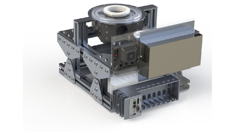
Mechanical Design: Spinner Assembly • Assembly of four magnets into “spinner” • Steel shunts form part of spinner structure • Assembly anticipated to be challenging
Mechanical Design: Frame • Speed (3600 RPM) and weight (~20 lb) of spinner assembly necessitate very robust structure • 1. 5” 80/20 extrusion frame
Mechanical Design: Glass Support • Cocktail glass must be suspended in spinner assembly • Materials must be nonmagnetic and nonconductive • Delrin cup in Lexan ring
Mechanical Design: Balancing • Spinner must be carefully balanced • Load cell on crossbar monitors centrifugal force • By correlating with shaft encoder, angular location of mass overburden can be found • Balance mass added on opposite side to balance spinner
Mechanical Design: Power • 12 VDC CIM motor drives spinner • Coupled to spinner shaft by #25 roller chain
Control System • MDL-BDC 24 PWM motor controller (40 A continuous) • Internal PID loop for velocity control • Controlled via CAN • National Instruments c. RIO-9022 controller • Realtime OS • FPGA backplane • 12 VDC, 50 A power supply
Control System • c. RIO monitors: • • Centrifugal force sensor Shaft encoder Motor voltage & current (via MDL-BDC 24) User interface • And controls: • MDL-BDC 24 • Main power contactor
Safety • c. RIO shuts down motor if monitored parameters exceed safe limits • MDL-BDC 24 can “brake” motor (short across armature) • “Emergency bushing” designed to limit maximum wobble of spinner • User behind barrier, at least for initial tests