Design Considerations Prof Dr Mohamed Omar Mousa Prod


. l")


 Hole drilling Drill Work Piece L 1 : Hole Depth 6200")
 Hole drilling Thread Cutting tool 2) Thread Cutting L 2 :")
 Hole drilling 2) Thread Cutting 3) Bolt (Stud) assembly. 6200")


 • Lower")


- Slides: 78
Design Considerations Prof. Dr. Mohamed Omar Mousa Prod. & Mech. Design Dept. Minia University 6200 ﻣﺤﻤﺪ ﻋﻤﺮ ﻣﻮﺳﻰ /. ﺩ. ﺃ
PART ”I” STRESS CONCENTRATION 6200 ﻣﺤﻤﺪ ﻋﻤﺮ ﻣﻮﺳﻰ /. ﺩ. ﺃ
1. Stress concentration l Stress concentration appears in mechanical elements due to sudden change in cross section. l It has negative effects: - Decrease the strength of element. - Tends to crack initiation. l Dimensions of stress raiser. 6200 ﻣﺤﻤﺪ ﻋﻤﺮ ﻣﻮﺳﻰ /. ﺩ. ﺃ
l Damage effect of stress raiser depends mainly on: 1. Value of load. 2. Type of load. 3. Dimensions & shape of stress raiser. 6200 ﻣﺤﻤﺪ ﻋﻤﺮ ﻣﻮﺳﻰ /. ﺩ. ﺃ
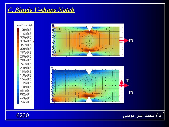
Shape of Stress Raisers: 1. Uni-axial stress Single V-notch Single Sharpedge Notch 6200 ﻣﺤﻤﺪ ﻋﻤﺮ ﻣﻮﺳﻰ /. ﺩ. ﺃ
Curved shoulder Single Semi-circular Notch 6200 ﻣﺤﻤﺪ ﻋﻤﺮ ﻣﻮﺳﻰ /. ﺩ. ﺃ
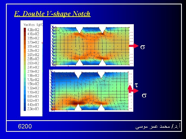
Effect of Double notch Shape 6200 ﻣﺤﻤﺪ ﻋﻤﺮ ﻣﻮﺳﻰ /. ﺩ. ﺃ
2. Bi-axial stress A. Effect of filet 6200 ﻣﺤﻤﺪ ﻋﻤﺮ ﻣﻮﺳﻰ /. ﺩ. ﺃ
B. Single Sharp-edge Notch 6200 ﻣﺤﻤﺪ ﻋﻤﺮ ﻣﻮﺳﻰ /. ﺩ. ﺃ
D. Single Semi-circular Notch 6200 ﻣﺤﻤﺪ ﻋﻤﺮ ﻣﻮﺳﻰ /. ﺩ. ﺃ
F. Double Sharp-edge Notches 6200 ﻣﺤﻤﺪ ﻋﻤﺮ ﻣﻮﺳﻰ /. ﺩ. ﺃ
7. Double Semi-circular Notch 6200 ﻣﺤﻤﺪ ﻋﻤﺮ ﻣﻮﺳﻰ /. ﺩ. ﺃ
3. Examples of Failed Elements Fatigue failure of a shaft 6200 ﻣﺤﻤﺪ ﻋﻤﺮ ﻣﻮﺳﻰ /. ﺩ. ﺃ
Pitting corrosion resulting from elevated temperatures on an aluminum housing. 6200 ﻣﺤﻤﺪ ﻋﻤﺮ ﻣﻮﺳﻰ /. ﺩ. ﺃ
A brittle fracture that originated at a surface defect. 6200 ﻣﺤﻤﺪ ﻋﻤﺮ ﻣﻮﺳﻰ /. ﺩ. ﺃ
Three conveyor rollers: q. The center one is “as supplied, ” q. The outer two have failed from contact stresses. q. The left roller was case hardened and cracked. q The right roller was unhardened and ductilly deformed. 6200 ﻣﺤﻤﺪ ﻋﻤﺮ ﻣﻮﺳﻰ /. ﺩ. ﺃ
Fracture due to Torsional effect. 6200 ﻣﺤﻤﺪ ﻋﻤﺮ ﻣﻮﺳﻰ /. ﺩ. ﺃ
Keyseat distortion Torsional force Keyway deformation due to shaft overloaded. 6200 ﻣﺤﻤﺪ ﻋﻤﺮ ﻣﻮﺳﻰ /. ﺩ. ﺃ
Ductile deformation due to shaft overloaded. 6200 ﻣﺤﻤﺪ ﻋﻤﺮ ﻣﻮﺳﻰ /. ﺩ. ﺃ
Part” 2” Stress Concentration Factor 6200 ﻣﺤﻤﺪ ﻋﻤﺮ ﻣﻮﺳﻰ /. ﺩ. ﺃ
2. Stress Concentration factor: Assume a simple plate (b x t x L). l The plate has a hole of diameter ”d”. l It is under axial force “F”. l Two different stress appears in member. t L l b 6200 ﻣﺤﻤﺪ ﻋﻤﺮ ﻣﻮﺳﻰ /. ﺩ. ﺃ
- Average stress “ av” - Average stress “ max” L max t av b 6200 ﻣﺤﻤﺪ ﻋﻤﺮ ﻣﻮﺳﻰ /. ﺩ. ﺃ
3. Stress Raisers: 3. 1 Holes 3. 1. 1 Holes in shafts 3. 1. 2 Holes in plates 6200 ﻣﺤﻤﺪ ﻋﻤﺮ ﻣﻮﺳﻰ /. ﺩ. ﺃ
3. 2 Notches 3. 2. 1 Notches in shafts 3. 2. 2 Notches in plates 6200 ﻣﺤﻤﺪ ﻋﻤﺮ ﻣﻮﺳﻰ /. ﺩ. ﺃ
3. 3 Sudden Change of Dimensions 3. 3. 1 900 Angle 3. 3. 2 Stepped Shafts 3. 3. 3 Stepped Plate 6200 ﻣﺤﻤﺪ ﻋﻤﺮ ﻣﻮﺳﻰ /. ﺩ. ﺃ
4. Relieving stress Reducing of stress concentration in the mechanical members. Factors affecting the efficiency of stress relief • Element (member) dimensions. • Raiser dimensions. • Load (Type, Value, Direction) 6200 ﻣﺤﻤﺪ ﻋﻤﺮ ﻣﻮﺳﻰ /. ﺩ. ﺃ
Part “ 3” Design Considerations Related to Machining 6200 ﻣﺤﻤﺪ ﻋﻤﺮ ﻣﻮﺳﻰ /. ﺩ. ﺃ
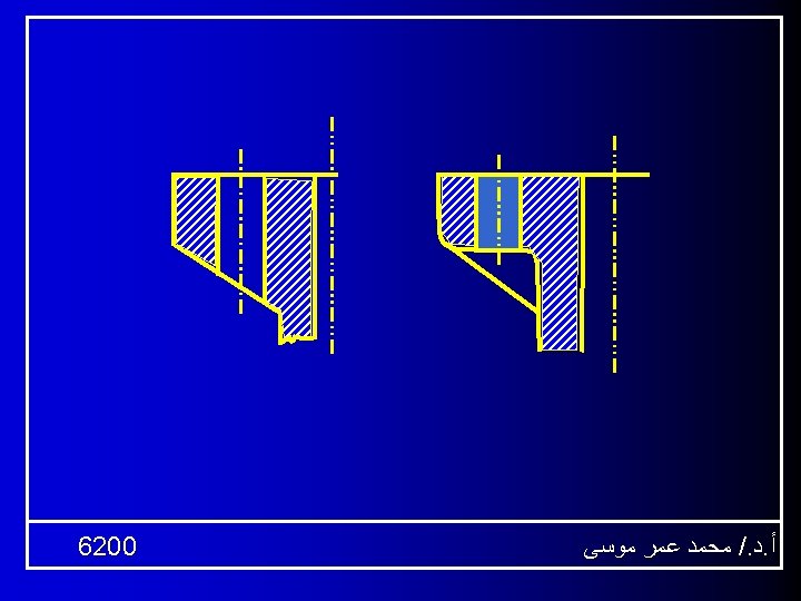
1. Drilling 1. 1 Drilling on inclined surfaces - Avoiding of drilling on inclined surfaces to prevent effect of tangential drilling (Cutting) force. 6200 ﻣﺤﻤﺪ ﻋﻤﺮ ﻣﻮﺳﻰ /. ﺩ. ﺃ
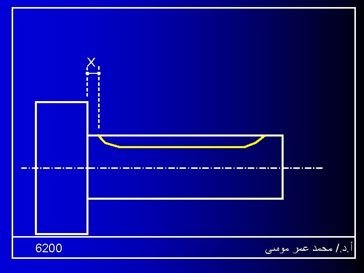
1. 2. Drilling of holes in relative small heights. X > D/2 H > D/2 X H 6200 ﻣﺤﻤﺪ ﻋﻤﺮ ﻣﻮﺳﻰ /. ﺩ. ﺃ
2. Tool tolerance for Threading - External Thread - Internal Thread Tolerance undercut External Thread 6200 Tolerance undercut Internal Thread ﻣﺤﻤﺪ ﻋﻤﺮ ﻣﻮﺳﻰ /. ﺩ. ﺃ
3. Tool tolerance for Milling 6200 ﻣﺤﻤﺪ ﻋﻤﺮ ﻣﻮﺳﻰ /. ﺩ. ﺃ
4. Tool tolerance By Grinding 6200 Grinding wheel ﻣﺤﻤﺪ ﻋﻤﺮ ﻣﻮﺳﻰ /. ﺩ. ﺃ
5. Base for assembly Guide for disc or washer assembly Guide for pin assembly 6200 ﻣﺤﻤﺪ ﻋﻤﺮ ﻣﻮﺳﻰ /. ﺩ. ﺃ
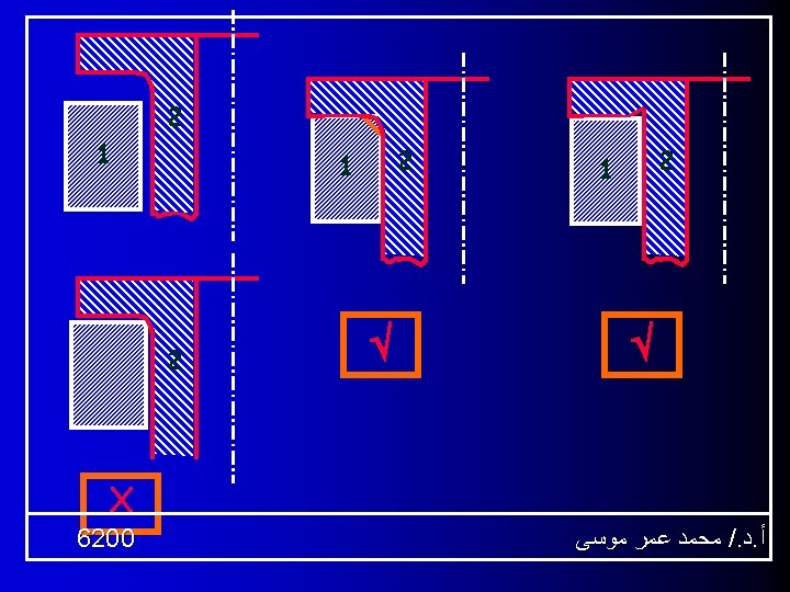
6. Perpendicular Surfaces Tool - Tip curvature of single point cutting tools deforms the corner of the perpendicular surfaces 6200 ﻣﺤﻤﺪ ﻋﻤﺮ ﻣﻮﺳﻰ /. ﺩ. ﺃ
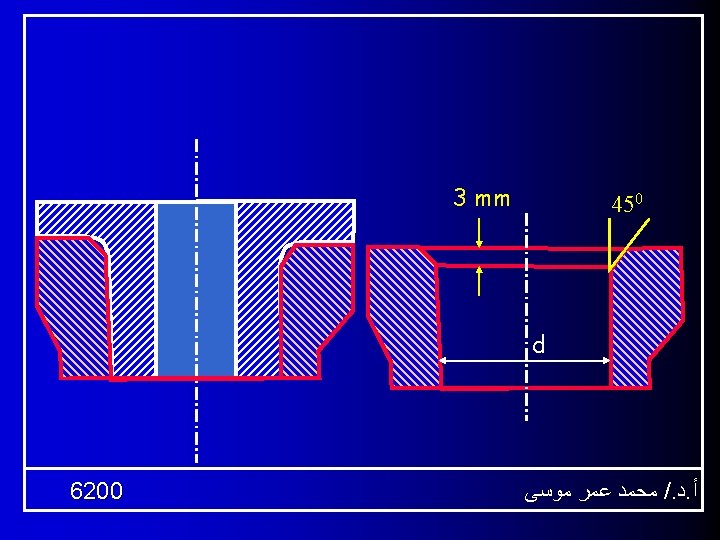
7. Pin Hole relationship Sharp Corner 6200 450 x 1. 5 ﻣﺤﻤﺪ ﻋﻤﺮ ﻣﻮﺳﻰ /. ﺩ. ﺃ
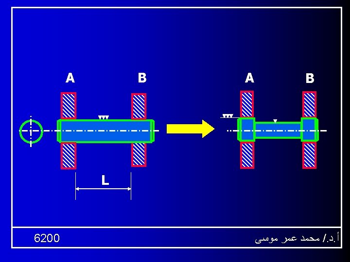
8. Avoiding of shoulder by tapered shaft ends - Hub fixation occurs when the contact surface between hub and both of washer and shoulder. 6200 ﻣﺤﻤﺪ ﻋﻤﺮ ﻣﻮﺳﻰ /. ﺩ. ﺃ
9. Assembly of Elements on Parallel Surfaces Cover Cylinder - Clearance between cover and cylinder is used. 6200 ﻣﺤﻤﺪ ﻋﻤﺮ ﻣﻮﺳﻰ /. ﺩ. ﺃ
10. Assembly of Elements on Parallel Surfaces - Partial contact between flat contact surfaces is better to avoid effect of out of flatness or distortion. 6200 ﻣﺤﻤﺪ ﻋﻤﺮ ﻣﻮﺳﻰ /. ﺩ. ﺃ
11. Bases of flat casting Elements - Bases of casting elements in the same level is recommended. 6200 ﻣﺤﻤﺪ ﻋﻤﺮ ﻣﻮﺳﻰ /. ﺩ. ﺃ
12. General Recommendations by Casting 6200 ﻣﺤﻤﺪ ﻋﻤﺮ ﻣﻮﺳﻰ /. ﺩ. ﺃ
- Casting of perpendicular surfaces. 6200 ﻣﺤﻤﺪ ﻋﻤﺮ ﻣﻮﺳﻰ /. ﺩ. ﺃ
- Casting of wheels with webs. 6200 ﻣﺤﻤﺪ ﻋﻤﺮ ﻣﻮﺳﻰ /. ﺩ. ﺃ
12. Strengthen of Vertical column 6200 ﻣﺤﻤﺪ ﻋﻤﺮ ﻣﻮﺳﻰ /. ﺩ. ﺃ
12. Strengthen of Vertical column 6200 ﻣﺤﻤﺪ ﻋﻤﺮ ﻣﻮﺳﻰ /. ﺩ. ﺃ
12. Strengthen of Vertical column 6200 ﻣﺤﻤﺪ ﻋﻤﺮ ﻣﻮﺳﻰ /. ﺩ. ﺃ
13. Gear Wheels F F F - Improvement of external gear strength by means of strengthening single (A) or double (B) web. 6200 ﻣﺤﻤﺪ ﻋﻤﺮ ﻣﻮﺳﻰ /. ﺩ. ﺃ
- Improvement of bevel gear strength. 6200 ﻣﺤﻤﺪ ﻋﻤﺮ ﻣﻮﺳﻰ /. ﺩ. ﺃ
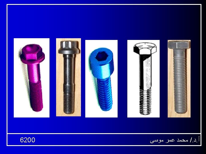
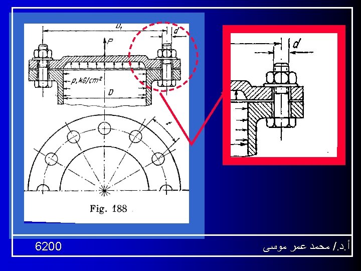
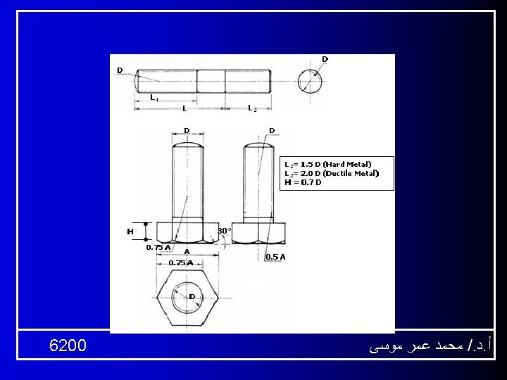
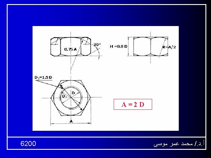
13. Bolts Connections - M 1 : M 8 Each 1 - M 8 : M 24 Each 2 L 1 0. 8 d Bolts series - M 48 Each 4 H (bolt Head) = 0. 7 d H (Nut) = 0. 8 d L 1 0. 7 d - M 24 : M 48 Each 3 2 d d. 5 d 1 = Variable 6200 Design- Make Nuts and bolts ﻣﺤﻤﺪ ﻋﻤﺮ ﻣﻮﺳﻰ /. ﺩ. ﺃ
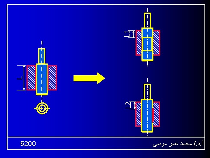
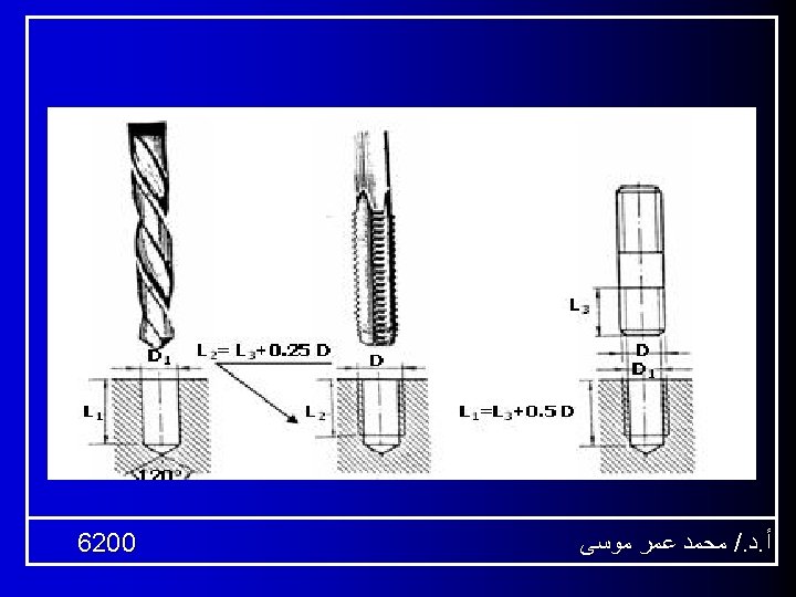
Bolts Connections 1) Hole drilling Drill Work Piece L 1 : Hole Depth 6200 ﻣﺤﻤﺪ ﻋﻤﺮ ﻣﻮﺳﻰ /. ﺩ. ﺃ
Bolts Connections 1) Hole drilling Thread Cutting tool 2) Thread Cutting L 2 : Thread Depth L 3 : Bolt Thread Depth 6200 ﻣﺤﻤﺪ ﻋﻤﺮ ﻣﻮﺳﻰ /. ﺩ. ﺃ
13. Bolts Connections 1) Hole drilling 2) Thread Cutting 3) Bolt (Stud) assembly. 6200 ﻣﺤﻤﺪ ﻋﻤﺮ ﻣﻮﺳﻰ /. ﺩ. ﺃ
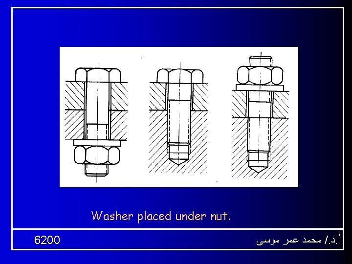
Steps of Stud Assembly 6200 Washer Nut ﻣﺤﻤﺪ ﻋﻤﺮ ﻣﻮﺳﻰ /. ﺩ. ﺃ
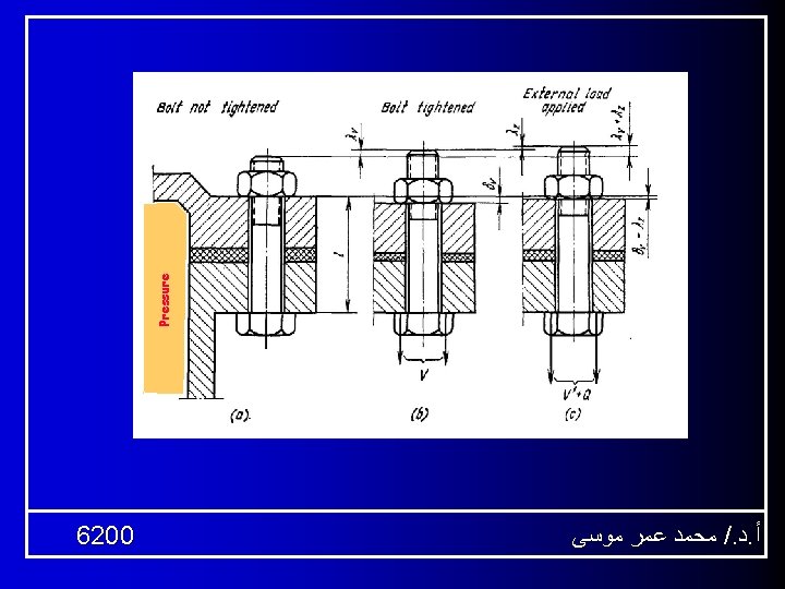
A. Through Bolt DHole = 1. 2 Dbolt • Bolt is under tension. • Elements are under compression. 6200 ﻣﺤﻤﺪ ﻋﻤﺮ ﻣﻮﺳﻰ /. ﺩ. ﺃ
B. Tap Bolt • Upper part has a hole (1. 2 d) • Lower part is threaded. • Connection occurs due to the mutual forces between: • 1 - Contact between Bolt head and surface of upper part. • 2 -Teeth of the bolt end 6200 ﻣﺤﻤﺪ ﻋﻤﺮ ﻣﻮﺳﻰ /. ﺩ. ﺃ
C. Stud Consist of two threaded parts and a cylindrical neck. One end is assembled in the base element and the other element is pressed by a net assembled in the other bolt end. Hole diameter of the upper part is (1. 2 d). 6200 ﻣﺤﻤﺪ ﻋﻤﺮ ﻣﻮﺳﻰ /. ﺩ. ﺃ
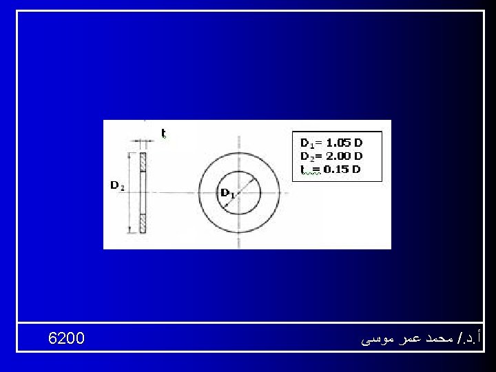
Relative Dimensions of Hole and Bolt D : Bolt Diameter ( D=30 For Bolt M 30) H 1 = 0. 8 D ( Nut Height) t (Washer height) = 0. 15 D D 2 = 2 D ( Washer Biggest width) A = 3 D ( Min. Surface of contact width) L 1 = 2 D +1. 25 (Thread of bolt length) L 2 = L 1 + 0. 25 D (Hole thread length) L 3 = L 1 + 0. 4 D (Hole depth) 6200 ﻣﺤﻤﺪ ﻋﻤﺮ ﻣﻮﺳﻰ /. ﺩ. ﺃ
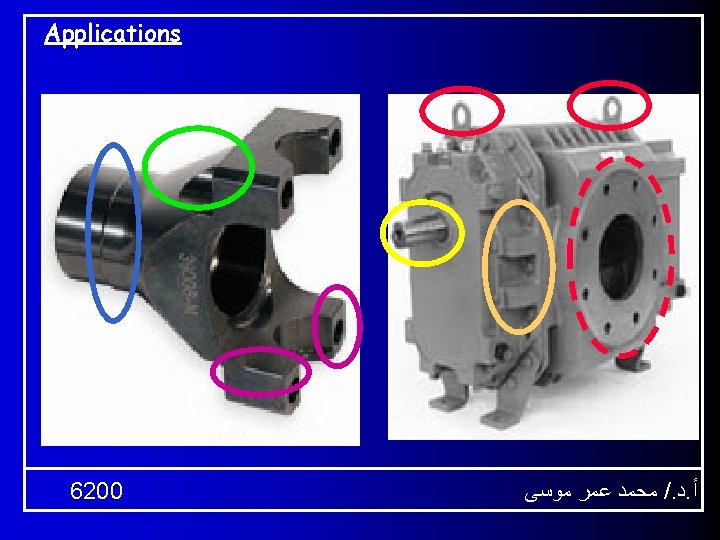
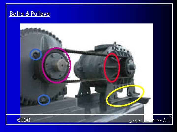
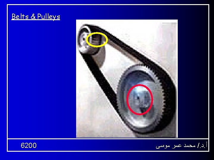
Belts & Pulleys Design 01 - 3 D CONVEYOR ANIMATION - FINAL PROJECT - 6200 ﻣﺤﻤﺪ ﻋﻤﺮ ﻣﻮﺳﻰ /. ﺩ. ﺃ
END January 2006 Prepared by Prof. Dr. Mohamed Omar Mousa