
Design and testing of the Beam Delivery System
Design and testing of the Beam Delivery System collimators for the International Linear Collider J. L. Fernandez-Hernando STFC/ASTe. C Daresbury Lab
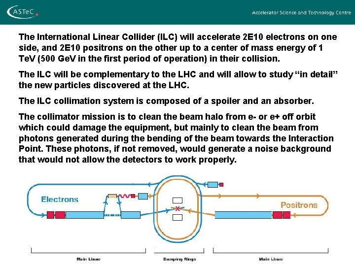
The International Linear Collider (ILC) will accelerate 2 E 10 electrons on one side, and 2 E 10 positrons on the other up to a center of mass energy of 1 Te. V (500 Ge. V in the first period of operation) in their collision. The ILC will be complementary to the LHC and will allow to study “in detail” the new particles discovered at the LHC. The ILC collimation system is composed of a spoiler and an absorber. The collimator mission is to clean the beam halo from e- or e+ off orbit which could damage the equipment, but mainly to clean the beam from photons generated during the bending of the beam towards the Interaction Point. These photons, if not removed, would generate a noise background that would not allow the detectors to work properly.
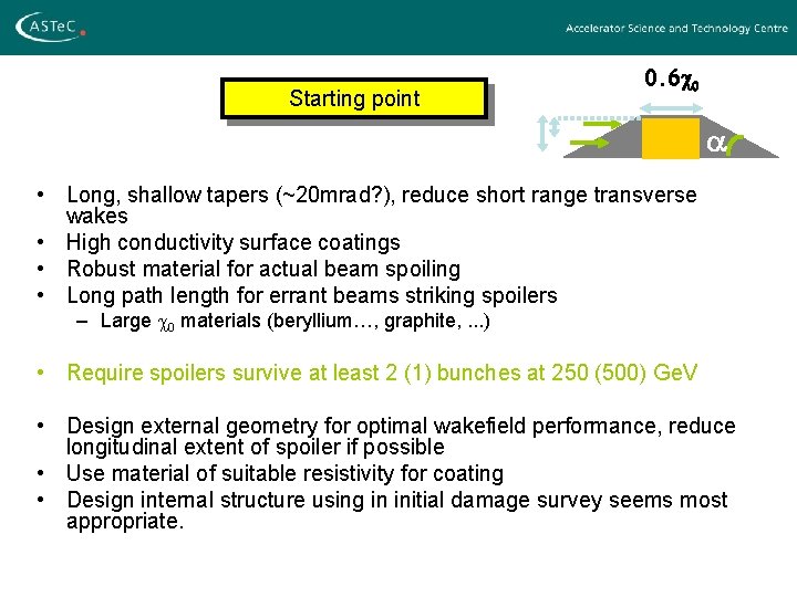
Starting point 0. 6 c 0 a • Long, shallow tapers (~20 mrad? ), reduce short range transverse wakes • High conductivity surface coatings • Robust material for actual beam spoiling • Long path length for errant beams striking spoilers – Large c 0 materials (beryllium…, graphite, . . . ) • Require spoilers survive at least 2 (1) bunches at 250 (500) Ge. V • Design external geometry for optimal wakefield performance, reduce longitudinal extent of spoiler if possible • Use material of suitable resistivity for coating • Design internal structure using in initial damage survey seems most appropriate.
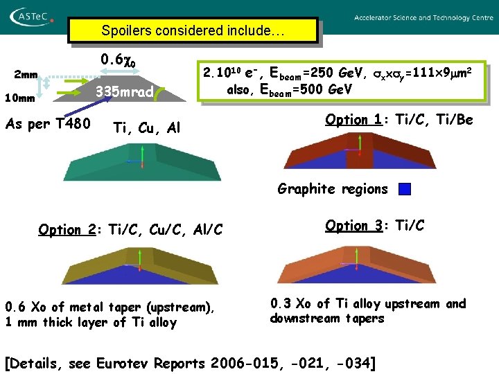
Spoilers considered include… 2 mm 10 mm As per T 480 0. 6 c 0 335 mrad 2. 1010 e-, Ebeam=250 Ge. V, sx sy=111 9 mm 2 also, Ebeam=500 Ge. V Ti, Cu, Al Option 1: Ti/C, Ti/Be Graphite regions Option 2: Ti/C, Cu/C, Al/C 0. 6 Xo of metal taper (upstream), 1 mm thick layer of Ti alloy Option 3: Ti/C 0. 3 Xo of Ti alloy upstream and downstream tapers [Details, see Eurotev Reports 2006 -015, -021, -034]
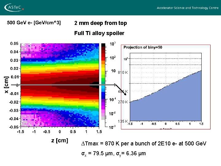
2 mm deep from top Full Ti alloy spoiler 810 K 405 K 270 K 135 K ∆Tmax = 870 K per a bunch of 2 E 10 e- at 500 Ge. V σx = 79. 5 µm, σy= 6. 36 µm
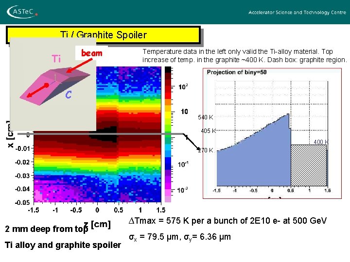
Ti / Graphite Spoiler beam Ti Temperature data in the left only valid the Ti-alloy material. Top increase of temp. in the graphite ~400 K. Dash box: graphite region. C 540 K 405 K 400 K 270 K 2 mm deep from top Ti alloy and graphite spoiler ∆Tmax = 575 K per a bunch of 2 E 10 e- at 500 Ge. V σx = 79. 5 µm, σy= 6. 36 µm
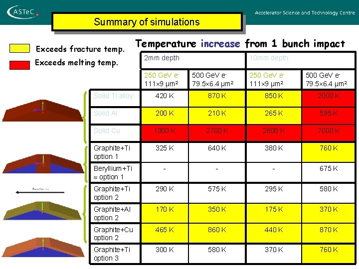
Summary of simulations Exceeds fracture temp. Exceeds melting temp. Temperature increase from 1 bunch impact 2 mm depth 250 Ge. V e 111 9 µm 2 10 mm depth 500 Ge. V e 79. 5 6. 4 µm 2 250 Ge. V e 111 9 µm 2 500 Ge. V e 79. 5 6. 4 µm 2 Solid Ti alloy 420 K 870 K 850 K 2000 K Solid Al 200 K 210 K 265 K 595 K Solid Cu 1300 K 2700 K 2800 K 7000 K Graphite+Ti option 1 325 K 640 K 380 K 760 K Beryllium+Ti option 1 - - - 675 K Graphite+Ti option 2 290 K 575 K 295 K 580 K Graphite+Al option 2 170 K 350 K 175 K 370 K Graphite+Cu option 2 465 K 860 K 440 K 870 K Graphite+Ti option 3 300 K 580 K 370 K 760 K
• Wakefields deteriorate the beam quality. • A final collimator design should minimise this effect. • Studies on wakefields generated by different collimator geometries. • Comparison to analytic predictions and simulations in order to improve both methods.
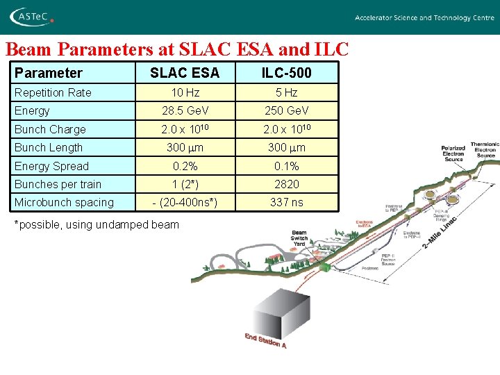
Beam Parameters at SLAC ESA and ILC Parameter SLAC ESA ILC-500 10 Hz 5 Hz Energy 28. 5 Ge. V 250 Ge. V Bunch Charge 2. 0 x 1010 Bunch Length 300 mm Energy Spread 0. 2% 0. 1% Bunches per train 1 (2*) 2820 - (20 -400 ns*) 337 ns Repetition Rate Microbunch spacing *possible, using undamped beam
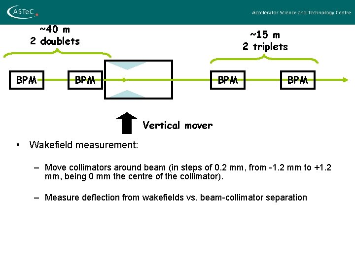
~40 m 2 doublets BPM ~15 m 2 triplets BPM BPM Vertical mover • Wakefield measurement: – Move collimators around beam (in steps of 0. 2 mm, from -1. 2 mm to +1. 2 mm, being 0 mm the centre of the collimator). – Measure deflection from wakefields vs. beam-collimator separation
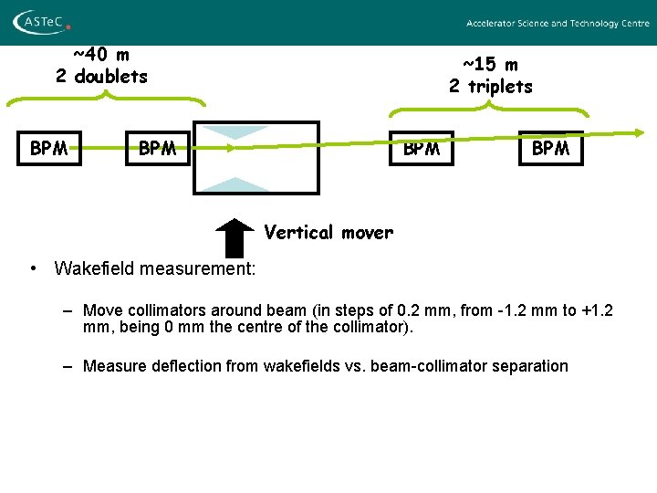
~40 m 2 doublets BPM ~15 m 2 triplets BPM BPM Vertical mover • Wakefield measurement: – Move collimators around beam (in steps of 0. 2 mm, from -1. 2 mm to +1. 2 mm, being 0 mm the centre of the collimator). – Measure deflection from wakefields vs. beam-collimator separation
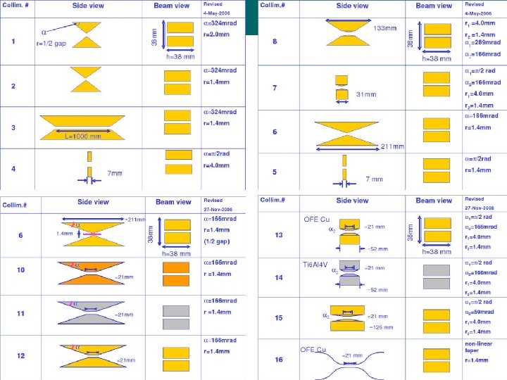
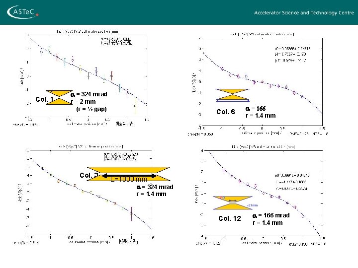
Col. 1 a = 324 mrad r = 2 mm (r = ½ gap) Col. 3 Col. 6 a = 166 r = 1. 4 mm L=1000 mm a = 324 mrad r = 1. 4 mm Col. 12 a = 166 mrad r = 1. 4 mm
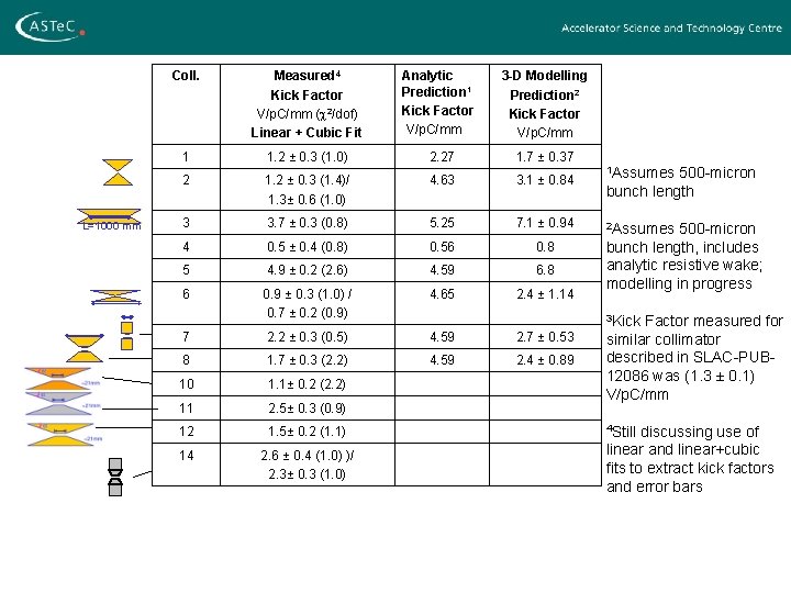
L=1000 mm Coll. Measured 4 Kick Factor V/p. C/mm (c 2/dof) Linear + Cubic Fit Analytic Prediction 1 Kick Factor V/p. C/mm 3 -D Modelling Prediction 2 Kick Factor V/p. C/mm 1 1. 2 ± 0. 3 (1. 0) 2. 27 1. 7 ± 0. 37 2 1. 2 ± 0. 3 (1. 4)/ 1. 3± 0. 6 (1. 0) 4. 63 3. 1 ± 0. 84 3 3. 7 ± 0. 3 (0. 8) 5. 25 7. 1 ± 0. 94 4 0. 5 ± 0. 4 (0. 8) 0. 56 0. 8 5 4. 9 ± 0. 2 (2. 6) 4. 59 6. 8 6 0. 9 ± 0. 3 (1. 0) / 0. 7 ± 0. 2 (0. 9) 4. 65 2. 4 ± 1. 14 7 2. 2 ± 0. 3 (0. 5) 4. 59 2. 7 ± 0. 53 8 1. 7 ± 0. 3 (2. 2) 4. 59 2. 4 ± 0. 89 10 1. 1± 0. 2 (2. 2) 11 2. 5± 0. 3 (0. 9) 12 1. 5± 0. 2 (1. 1) 14 2. 6 ± 0. 4 (1. 0) )/ 2. 3± 0. 3 (1. 0) 1 Assumes 500 -micron bunch length 2 Assumes 500 -micron bunch length, includes analytic resistive wake; modelling in progress 3 Kick Factor measured for similar collimator described in SLAC-PUB 12086 was (1. 3 ± 0. 1) V/p. C/mm 4 Still discussing use of linear and linear+cubic fits to extract kick factors and error bars
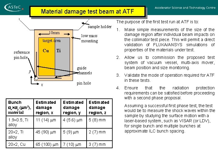
Material damage test beam at ATF sample holder 10 mm Cu 1. Make simple measurements of the size of the damage region after individual beam impacts on the collimator test piece. This will permit a direct validation of FLUKA/ANSYS simulations of properties of the materials under test. 2. Allow us to commission the proposed test system of vacuum vessel, multi-axis mover, beam position and size monitoring. 3. Validate the mode of operation required for ATF in these tests. 4. Ensure that the radiation protection requirements can be satisfied before proceeding with a second phase proposal. low mass mounting target area reference pin hole The purpose of the first test run at ATF is to: Ti guide channels y x pin hole Bunch sx sy (mm 2), material Estimated damage region, x Estimated damage region, y Estimated damage region, z 1. 9 0. 5, Ti alloy 11 (14) mm 4 (5. 6) mm 5 (8) mm 20 2, Ti alloy 45 (90) mm 5 (9) mm 2 (7) mm 20 2, Cu 65 (100) mm 7 (10) mm 3 (7) mm Assuming a successful first phase test, the test would be to measure the shock waves within the sample by studying the surface motion with a laser-based system, such as VISAR (or LDV), for single bunch and multiple bunches at approximate ILC bunch spacing.
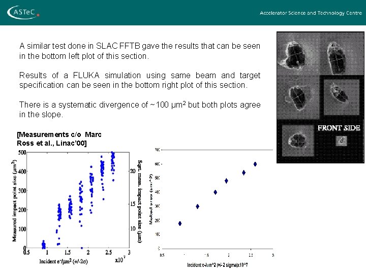
A similar test done in SLAC FFTB gave the results that can be seen in the bottom left plot of this section. Results of a FLUKA simulation using same beam and target specification can be seen in the bottom right plot of this section. There is a systematic divergence of ~100 µm 2 but both plots agree in the slope. [Measurements c/o Marc Ross et al. , Linac’ 00]
Summary & Future Plans • Resulting mechanical stresses examined with ANSYS 3 D • Continue study into beam damage/materials – Experimental beam test to reduce largest uncertainties in material properties • Study geometries which can reduce overall length of spoilers while maintaining performance • Means of damage detection, start engineering design of critical components • Combine information on geometry, material, construction, to find acceptable baseline design for – Wakefield optimisation – Collimation efficiency – Damage mitigation
- Slides: 17