
Design and Analysis of a HyperHemispherical ALON Dome
- Slides: 13
Design and Analysis of a Hyper-Hemispherical ALON™ Dome for Airborne Applications Michael J. Bender Robert C. Guyer Information included herein is controlled under the International Traffic in Arms Regulations (ITAR) by the U. S Department of State. Export or transfer of this information to a foreign person or foreign entity requires an export license issued by the U. S. State Department or an ITAR exemption to the license requirement prior to the export or transfer.
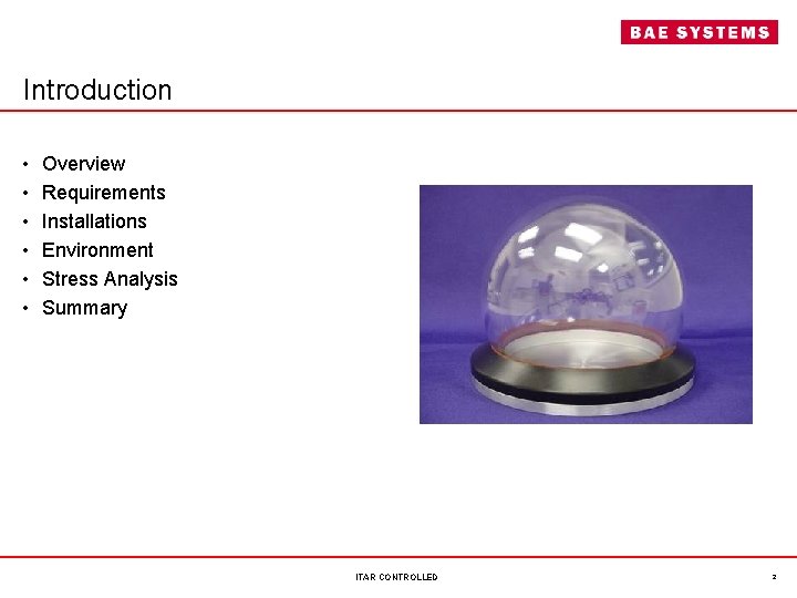
Introduction • • • Overview Requirements Installations Environment Stress Analysis Summary ITAR CONTROLLED 2
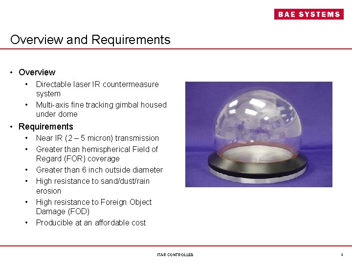
Overview and Requirements • Overview • Directable laser IR countermeasure system • Multi-axis fine tracking gimbal housed under dome • Requirements • Near IR (2 – 5 micron) transmission • Greater than hemispherical Field of Regard (FOR) coverage • Greater than 6 inch outside diameter • High resistance to sand/dust/rain erosion • High resistance to Foreign Object Damage (FOD) • Producible at an affordable cost ITAR CONTROLLED 3
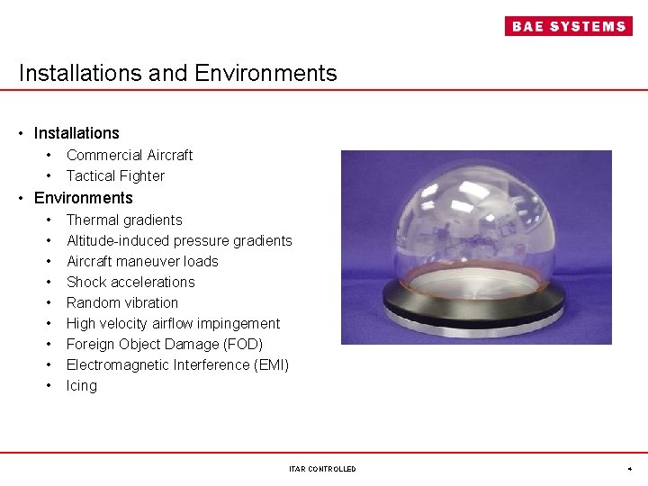
Installations and Environments • Installations • Commercial Aircraft • Tactical Fighter • Environments • • • Thermal gradients Altitude-induced pressure gradients Aircraft maneuver loads Shock accelerations Random vibration High velocity airflow impingement Foreign Object Damage (FOD) Electromagnetic Interference (EMI) Icing ITAR CONTROLLED 4
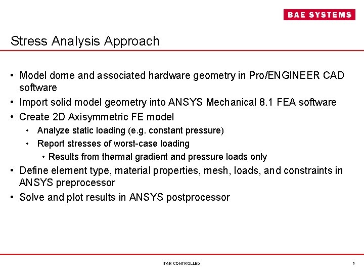
Stress Analysis Approach • Model dome and associated hardware geometry in Pro/ENGINEER CAD software • Import solid model geometry into ANSYS Mechanical 8. 1 FEA software • Create 2 D Axisymmetric FE model • Analyze static loading (e. g. constant pressure) • Report stresses of worst-case loading • Results from thermal gradient and pressure loads only • Define element type, material properties, mesh, loads, and constraints in ANSYS preprocessor • Solve and plot results in ANSYS postprocessor ITAR CONTROLLED 5
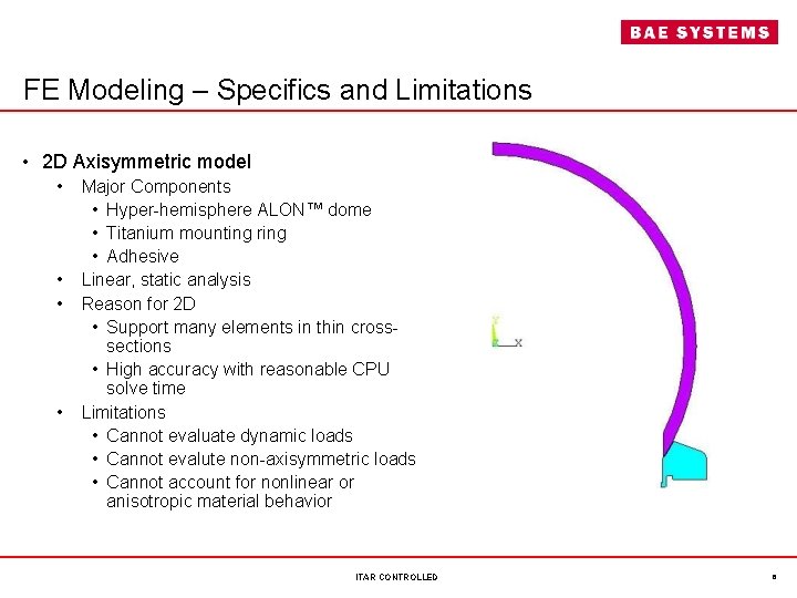
FE Modeling – Specifics and Limitations • 2 D Axisymmetric model • Major Components • Hyper-hemisphere ALON™ dome • Titanium mounting ring • Adhesive • Linear, static analysis • Reason for 2 D • Support many elements in thin crosssections • High accuracy with reasonable CPU solve time • Limitations • Cannot evaluate dynamic loads • Cannot evalute non-axisymmetric loads • Cannot account for nonlinear or anisotropic material behavior ITAR CONTROLLED 6
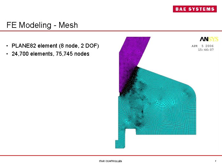
FE Modeling - Mesh • PLANE 82 element (8 node, 2 DOF) • 24, 700 elements, 75, 745 nodes ITAR CONTROLLED 7
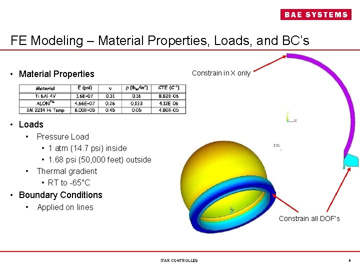
FE Modeling – Material Properties, Loads, and BC’s • Material Properties Constrain in X only • Loads • Pressure Load • 1 atm (14. 7 psi) inside • 1. 68 psi (50, 000 feet) outside • Thermal gradient • RT to -65°C • Boundary Conditions • Applied on lines Constrain all DOF’s ITAR CONTROLLED 8
FE Modeling - Results • Which computed stresses are appropriate? • Titanium ring • Ductile material with normal and shear loads • Von Mises equivalent stress considered most relevant • Adhesive • Primarily concerned with in-plane shear stress • ALON™ • Von Mises stress not suitable for brittle materials • In spherical regions of dome (away from geometric irregularities), primarily concerned with membrane stresses (meridional and hoop) • Spherical coordinate system, centered at optical center of dome, is used to make stress calculations • Simplifies determination of stress direction (tensile or compressive) ITAR CONTROLLED 9
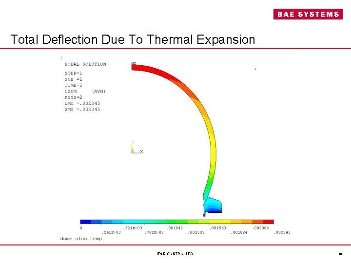
Total Deflection Due To Thermal Expansion ITAR CONTROLLED 10
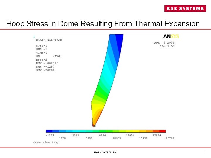
Hoop Stress in Dome Resulting From Thermal Expansion ITAR CONTROLLED 11
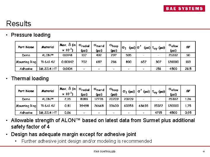
Results • Pressure loading • Thermal loading • Allowable strength of ALON™ based on latest data from Surmet plus additional safety factor of 4 • Design has adequate margin except for adhesive joint • Further adhesive joint design and/or modeling is recommended ITAR CONTROLLED 12
Summary • Resultant stresses from thermal loading are worst-case • Highest stress in dome occurs where section is reduced near Ti frame • Except for adhesive under thermal loading, all calculated stresses are below maximum allowable stresses • Strength of ALON™ derived from latest data from Surmet • Strength of adhesive bonds dependent on the following • Surface preparation • Environment (temperature, humidity, etc. ) • Choice of substrate materials • Further analysis and application-specific environmental testing recommended • The impressive mechanical properties of ALON™ make it a viable candidate for high speed aircraft installations ITAR CONTROLLED 13