Design Analysis of Pelton Wheel Turbine P M

Design & Analysis of Pelton Wheel Turbine P M V Subbarao Professor Mechanical Engineering Department Internal Details of the Machine….

Koyna Hydro Electric Project Koyna Dam from the catchment area of about 891. 78 Sq. Km • Koyna river rises in the Mahabaleshwar, a famous hill station in the hill range of Sahyadri. • It flows in a north - south direction almost parallel to the Arabian Sea coast for a distance of 65 Kms.

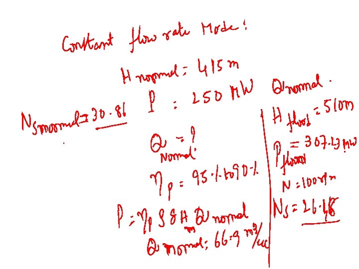
Details of Koyna Hydro Electric Project • Number of units: 4 • Capacity of each unit=250 MW • Head – Normal Head=415 m – Maximum Head=510 m

Creation of Reservoir

Specific speed in rpm MORE ADAPTED TYPE OF TURBINA IN FUNCTION OF THE SPECIFIC SPEED. Specific Speed in Turbine type Jump height in m r. p. m. Until 18 Pelton of an injector 800 From 18 to 25 Pelton of an injector 800 to 400 From 26 to 35 Pelton of an injector 400 to 100 From 26 to 35 Pelton of two injectors 800 to 400 From 36 to 50 Pelton of two injectors 400 to 100 From 51 to 72 Pelton of four injectors 400 to 100

Selection of Speed of A Turbo Machine Zp : Number of pairs of poles of the generator
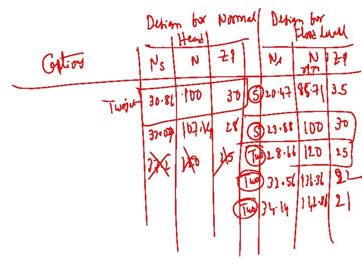

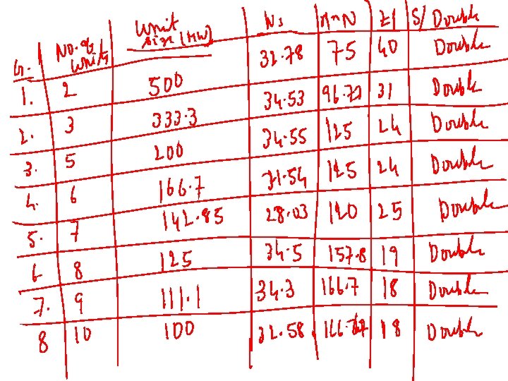
Questions to be Answered • Is it possible to change number of units in Stage IV? • What is the allowable speed of the generator for each unit, if number of units is 2, 5, 6 or 7?

Design of Any Selected Pelton Wheel Unit • • Different capacities for each sub-group. Design for Normal Head. Assume an overall efficiency: 90 – 94% Calculate the required flow rate.

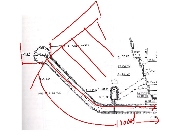
General Layout of A Hydro Power Plant

THE CONDUIT SYSTEM • Water from the storage is diverted into the main conduit system through a 3, 370 ft long intake channel and an intake tower, trash racks and two intake gates each 21 ft. X 8 ft. • The head race tunnel is 12, 000 ft long and 21 ft in diameter. • It is concrete lined for the whole of the length expect for the last 1600 ft at the surge end where 17 ft diameter steel lining is provided. • The diameter of the tunnel, in the stretch of steel lining is reduced on ground of economy

Pipe Material Open Channel Gravity Channel drawn brass Bed drawn Slopecopper commercial steel wrought iron asphalted cast iron galvanized iron cast iron wood stave Absolute Roughness, e micron Flow(unless noted) 1. 5 45 45 120 150 260 0. 2 to 0. 9 mm concrete 0. 3 to 3 mm riveted steel 0. 9 to 9 mm

Design of Penstock In general But maximum allowable value is 10 m/s Maximum allowable head loss in Penstock =2 to 4% of available head

General Design of Under Ground Power Tunnels/Penstocks

Pipe Material drawn brass drawn copper commercial steel wrought iron asphalted cast iron galvanized iron cast iron wood stave Absolute Roughness, e micron (unless noted) 1. 5 45 45 120 150 260 0. 2 to 0. 9 mm concrete 0. 3 to 3 mm riveted steel 0. 9 to 9 mm

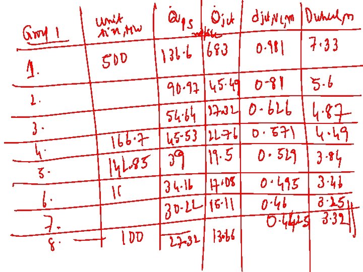
Design of Penstock Group No. Unit Size MW 1. 500 2. 333. 3 3. 200 4. 166. 7 5. 142. 85 6. 125 7. 111. 1 8. 100 Qp Dp Head loss

Distributor : Only for multi jet Wheel

Design of Distributor Penstock Q

The Nozzle and Jet : A Key Step in Design b a djet, VC Free Surface Shape for Maximum Power d 0

Initial guess for Diameter of the Jet at the outlet, do It is important to find out the VC and outlet jet diameters/areas

Geometrical Relations for Nozzle 1. 1 d. O – 1. 3 d. O 2 d. O – 2. 4 d. O 0. 8 d. O – 0. 9 d. O 5 d. O – 9 d. O 1. 2 d. O – 1. 4 d. O

Performance Analysis of Nozzle-Spear Valve Ideal Nozzle-spear Valve: Along flow direction Real Nozzle-spear Valve:

Pipe Material drawn brass drawn copper commercial steel wrought iron asphalted cast iron galvanized iron cast iron wood stave Absolute Roughness, e micron (unless noted) 1. 5 45 45 120 150 260 0. 2 to 0. 9 mm concrete 0. 3 to 3 mm riveted steel 0. 9 to 9 mm

Numerical Computation of Total Pressure Variation

Efficiency of Spear Nozzle Valve Acceptable Range: 97. 5% -- 99%

Design of Penstock Group No. Unit Size MW 1. 500 2. 333. 3 3. 200 4. 166. 7 5. 142. 85 6. 125 7. 111. 1 8. 100 djet Head loss

Geometrical Relations for Nozzle The values of α varies between 20 to 30° whereas β varies from 30 to 45°.

Industrial Correlations for Jet Area variation with stroke Optimal value of Outlet jet area, ao s is the displacement of spear

Computation of Variation Jet Area with stroke

Mean Diameter of Pelton Runner Mean diameter or Pitch circle diameter: Dwheel Circumferential velocity of the wheel, Uwheel

Experimental values of Wheel diameter to jet diameter Dwheel /djet, VC 6. 5 7. 5 10 20 Ns (rpm) hturbine 35 0. 82 32 0. 86 24 0. 89 10 0. 90 Higher ratios are preferred for better efficiency. Modern wheels for high heads use ratios as high as 30!

Optimal values of Wheel diameter to jet diameter 30 25 20 15 10 5 0 0 5 10 15 20 25 30 Ns 35 40 45 50

Group No. Unit Size MW 1. 500 2. 333. 3 3. 200 4. 166. 7 5. 142. 85 6. 125 7. 111. 1 8. 100

Geometric Details of Bucket The hydraulic efficiency depends more on the main bucket dimensions (length (A), width (B) and depth (C)). The shape of the outer part of its rim or on the lateral surface curvature also has marginal effect on hydraulic efficiency.

Empirical Geometry of Bucket Shape III II C IV V I DW S 2 bi A be B

Empirical Relations for Bucket Geometry • • • A = 2. 8 djet, VC to 3. 2 djet, VC B = 2. 3 djet, VC to 2. 8 djet, VC C= 0. 6 djet, VC to 0. 9 djet, VC bi = 50 to 80 be is varied from section I to section V I: 300 to 460 II: 200 to 300 III: 100 to 200 IV: 50 to 160 V: 00 to 50

Number of Buckets d RP d. O, Vj, O RW w q lj y

Maximum allowable angle between two successive buckets Minimum number of buckets Dr Taygun has suggested an empirical relation for z

Group No. Unit Size MW 1. 500 2. 333. 3 3. 200 4. 166. 7 5. 142. 85 6. 125 7. 111. 1 8. 100

Absolute and Relative Paths of Jet : Orthogonal Interactions Vjet Ublade be ae Vrel, jet, exit Vjet, exit Ublade

Define Blade Speed Ratio, f

Approximate Velocity Triangles: Pelton Bucket

Start of Jet Bucket Interactions

Sequence of Jet Bucket Interactions Dq=50 Dq=150 Dq=250 Dq=350

Bucket Duty Cycle • Compute angles of onset and close of interactions. • Select few locations during bucket jet interaction. • Compute mass of jet intercepted by the bucket and corresponding blade exit angles. • Numerically integrate the work done by a bucket per rotation. • Compute Average Power developed by bucket and efficiency.
- Slides: 49