Design a Brief Introduction Infused Dr Offer Shai

Design: a Brief Introduction Infused Dr. Offer Shai and Prof. Yoram Reich Department of Mechanics, Materials and Systems Faculty of Engineering Tel-Aviv University

Infused design - is an approach for establishing effective collaboration between designers from different engineering fields. In this talk we will introduce the mathematical foundation underlying the approach, which mainly consists of discrete general mathematical models called graph representations. The representations are currently based on linear graph theory, but are being also expanded to other fields, such as matroid theory, bond graphs, discrete linear programming and others.

The outline of the lecture • Representing an engineering system through a graph containing both structural and geometrical properties of the system and capable of reflecting systems behavior. • Transforming engineering knowledge between different engineering domains through graph relations and its application to design. • Demonstrating the idea from a general perspective.

Let us consider a simple gear system 2 C B 1 A

Building the graph representation of the system 0 C A 1 2 C r. C B r. B 1 A r. A B 2

The equations underlying the system behavior 0 C A 1 B 2 C r. C w 1/0 B r. B 1 A r. A x w 1/0 2

The equations underlying the system behavior 0 C A 1 B 2 2 C r. C w 1/0+w 2/1 B r. B 1 A r. A x w 1/0+r. B x w 2/1

The equations underlying the system behavior 0 C A 1 B 2 2 C r. C w 1/0+w 2/1+w 2/0=0 B r. B 1 A r. A x w 1/0+r. B x w 2/1+r. C x w 2/0=0

The equations underlying the system behavior 0 C A 1 B 2 2 C r. C w 1/0+w 2/1+w 2/0=0 B r. B 1 A r. A x w 1/0+r. B x w 2/1+r. C x w 2/0=0

These equations can now be derived directly from the graph 0 C A 1 B 2 2 C r. C w 1/0+w 2/1+w 2/0=0 B r. B 1 A r. A x w 1/0+r. B x w 2/1+r. C x w 2/0=0

These equations can now be derived directly from the graph 0 C A 1 B 2 2 C r. C D 1/0+w 2/1+w 2/0=0 B r. B 1 A r. A x D 1/0+r. B x w 2/1+r. C x w 2/0=0

These equations can now be derived directly from the graph 0 C A 1 B 2 2 C r. C D 1/0+D 2/1+w 2/0=0 B r. B 1 A r. A x D 1/0+r. B x D 2/1+r. C x w 2/0=0

These equations can now be derived directly from the graph 0 C A 1 B 2 2 C r. C D 1/0+D 2/1+D 2/0=0 B r. B 1 A r. A x D 1/0+r. B x D 2/1+r. C x D 2/0=0

Building the dual graph C 0 A 0 B A 1 C I B 2 2 C r. C D 1/0+D 2/1+D 2/0=0 B r. B 1 A r. A x D 1/0+r. B x D 2/1+r. C x D 2/0=0

Building the dual graph C C 0 B A A 0 A 1 C I B B 2 2 C r. C D 1/0+D 2/1+D 2/0=0 B r. B 1 A r. A x D 1/0+r. B x D 2/1+r. C x D 2/0=0

Same behavioral equations can be derived from the dual graph C 0 0 C A 1 B B A I 2 2 C r. C F 1/0+D 2/1+D 2/0=0 B r. B 1 A r. A x F 1/0+r. B x D 2/1+r. C x D 2/0=0

Same behavioral equations can be derived from the dual graph C 0 0 C A 1 B B A I 2 2 C r. C F 1/0+F 2/1+D 2/0=0 B r. B 1 A r. A x F 1/0+r. B x F 2/1+r. C x D 2/0=0

Same behavioral equations can be derived from the dual graph C 0 0 C A 1 B B A I 2 2 C r. C F 1/0+F 2/1+F 2/0=0 B r. B 1 A r. A x F 1/0+r. B x F 2/1+r. C x F 2/0=0

Same behavioral equations can be derived from the dual graph C 0 0 C A 1 B B A I 2 2 C r. C F 1/0+F 2/1+F 2/0=0 B r. B 1 A r. A x F 1/0+r. B x F 2/1+r. C x F 2/0=0

From the dual graph we construct the dual engineering system C 0 0 C A 1 B B A I 2 2 C r. C C F 1/0+F 2/1+F 2/0=0 B r. B 1 A r. A x F 1/0+r. B x F 2/1+r. C x F 2/0=0 r. C B r. B A r. A

Behavioral isomorphism between the two dual engineering systems C 0 0 C A 1 B B A I 2 2 C r. C C PA+F 2/1+F 2/0=0 B r. B 1 A r. A x PA+r. B x F 2/1+r. C x F 2/0=0 r. C B r. B A r. A

Behavioral isomorphism between the two dual engineering systems C 0 0 C A 1 B A B I 2 2 C r. C C PA+RB+F 2/0=0 B r. B 1 A r. A x PA+r. B x RB+r. C x F 2/0=0 r. C B r. B A r. A

Behavioral isomorphism between the two dual engineering systems C 0 0 C A 1 B A B I 2 2 C r. C C PA+RB+RC=0 B r. B 1 A r. A x PA+r. B x RB+r. C x RC=0 r. C B r. B A r. A

Behavioral isomorphism between the two dual engineering systems C 0 0 C A 1 B A B I 2 2 C r. C C PA+RB+RC=0 B r. B 1 A r. A x PA+r. B x RB+r. C x RC=0 r. C B r. B A r. A

Employing this relation for design. Example case - design of a force amplifier C 0 0 C A 1 B B A I 2 2 C C B B 1 A A

Employing this relation for design. Example case - design of a force amplifier C 0 A 0 C A 1 B I B 2 2 Pin C Pout System to be found C B 1 A Pin Force amplifier Pout=1000 PAin

Transforming the design problem to the dual engineering domain 0 C A 1 Graph representation to be found Fout=1000 Fin B 2 2 C B 1 A Pin Force amplifier Pout=1000 PAin Fout

Transforming the design problem to the dual engineering domain Dual graph representation to be found Δout=1000 Δin Dout Graph representation to be found Fout=1000 Fin 2 C B 1 A Pin Force amplifier Pout=1000 PAin Fout

Transforming the design problem to the dual engineering domain Dual graph representation to be found Δout=1000 Δin Din win Gear system to be found ωout=1000 ωin Dout wout Graph representation to be found Fout=1000 Fin Pin Force amplifier Pout=1000 PAin Fout
 Dual graph representation")
Searching for existent engineering designs in the dual domain (gear systems) Dual graph representation to be found Δout=1000 Δin Din win Gear system to be found ωout=1000 ωin Dout wout Pin C B 1 win Graph representation to be found Fout=1000 Fin G A 2 3 C B A 4 5 G Force amplifier Pout=1000 PAin Fout

Transforming the solution back to the original design problem Din Dual graph 4 5 3 representation to be found Δout=1000 Δin 0 2 1 C B 1 win G Dout Graph representation to be found Fout=1000 Fin C 2 A B 4 A 3 5 G wout Pin Force amplifier Pout=1000 PAin Fout

Transforming the solution back to the original design problem Din 1 Dual graph A B A 3 4 5 representation C G to be found Δout=1000 Δin 0 B G 2 C B 1 win G Dout Graph representation to be found Fout=1000 Fin C 2 A B 4 A 3 5 G wout Pin Force amplifier Pout=1000 PAin Fout

Transforming the solution back to the original design problem 0 Din Dual graph A B A 3 4 5 representation C II G III C IV G to be found Δout=1000 Δin 0 B 1 G I 2 C B 1 win G Dout Graph representation to be found Fout=1000 Fin C 2 A B 4 A 3 5 G wout Pin Force amplifier Pout=1000 PAin Fout

Transforming the solution back to the original design problem 0 Din Dual graph A B A 3 4 5 representation C II G III C IV G to be found Δout=1000 Δin 0 B 1 G I 2 C B 1 win G Dout Fin G Graph representation B A to be found G C FCout=1000 F in Fout G C 2 A B 4 A 3 5 G wout Pin Force amplifier Pout=1000 PAin

Constructing the solution to the original design problem Din 1 Dual graph A B A 3 4 5 representation C G to be found Δout=1000 Δin 0 B G 2 C B 1 win G Dout Fin G A B 4 G B A A 3 Fout C C 2 Graph 0 representation B A to be found C G C I Fout=1000 F II III in IV 5 G wout P Pin I G Beam system II IV to be found Pout=1000 Pin Pout

Formalizing the approach B 1 2 A C G 3 B G 4 A C 5 0 G G B A Dual PLGR Potential Line 0 Graph I Representation C G II G FLGR C Flow Line IIIGraph Representation C 2 4 3 5 B B Planetary 1 gear systems A A win C B Determinate beams G wout P I II IV A IV G

Formalizing the approach 1 G B 2 A C 3 B G 4 C A 5 0 G G 0 A I PLGR Potential Line Graph Representation Planetary gear systems C B C Dual C B II G FLGR Flow Line Graph Representation Determinate beams III A C IV G

Same representations used to represent other engineering domains Dual PLGR Flow Line Graph Representation Potential Line Graph Representation Plane kinematical linkage Serial robots Serial robot Planetary gear systems C C Stewart platform Pillar system Determinate beams Stewa rt platfo rm

Same representations used to represent other engineering domains Dual PLGR Flow Line Graph Representation Potential Line Graph Representation Plane kinematical linkage Serial robots Serial robot Planetary gear systems C C Stewart platform Pillar system Determinate beams Stewa rt platfo rm

Additional graph representations have been developed and associated with additional engineering domains Dual PLGR Flow Line Graph Representation Potential Line Graph Representation Plane kinematical linkage Serial robots Planetary gear systems Stewart platform Pillar system Determinate beams Click here to continue

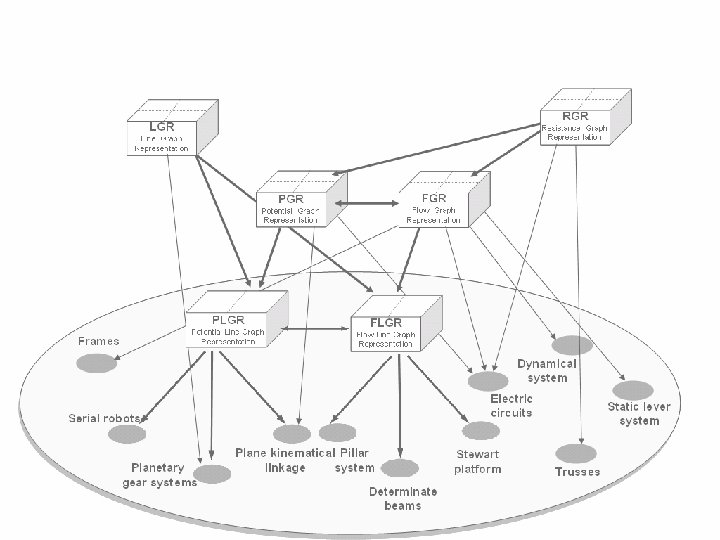
This methodology can now be applied for design in wide variety of engineering domains RGR LGR Resistance Graph Representation Line Graph Representation PLGR Potential Line Graph Representation Frames Serial robots PGR Potential Graph Representation Plane kinematical linkage Planetary gear systems Dual FLGR Flow Line Graph Representation Flow Graph Representation Pillar system Dynamical system Stewart platform Electronic Determinate. Static lever circuits beams system Trusses

Another design case: this time the knowledge is transformed from electronics PGR Potential Graph Representation Electronic circuits Planetary gear systems

Another design case: this time the knowledge is transformed from electronics Din Dout Potential graph representation PGR Graph to Potential be found Representation Δout=|Δin| Vin win Design a unidirectional Planetary Gear train gear systems ωout=|ωin| Design a voltage Rectifier Vout =|Vin| Electronic circuits wout Vout

Another design case: this time the knowledge is transformed from electronics Din A 5 Potential B graph C A 2 representation PGR 4 1 Graph to Potential be found Representation B 3 Δout. O 6=|ΔD in| C Dout Domain of electrical concepts Domain of gear train concepts Vin win Design a C A D unidirectional Planetary C D Btrain Gear gear systems ωout=|ωin| Design a voltage rectifier Vout. Electric =|Vin| Vout circuits A wout 5 2 4 D C 6 3 B
- Slides: 45