
Description of pixel designs in Mimosa 22 Andrei
- Slides: 27
Description of pixel designs in Mimosa 22 Andrei Dorokhov Institut Pluridisciplinaire Hubert Curien (IPHC) Strasbourg, France 03/04/2008 e-mail address: Andrei. Dorokhov@IRe. S. in 2 p 3. fr A. Dorokhov, IPHC, Strasbourg,
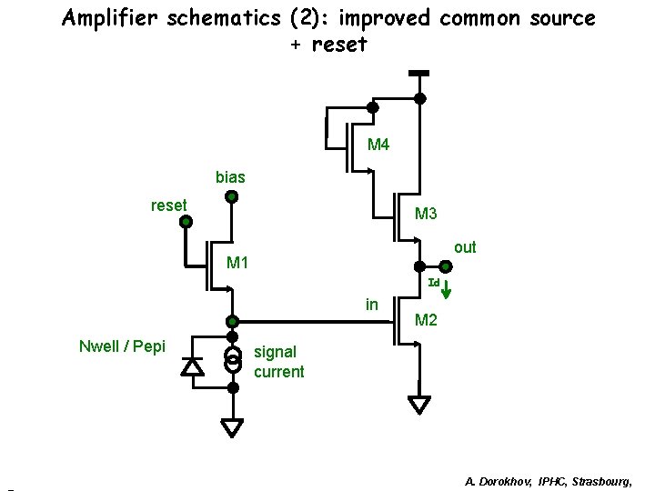
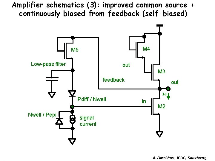
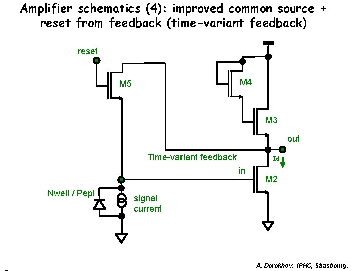
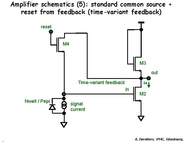
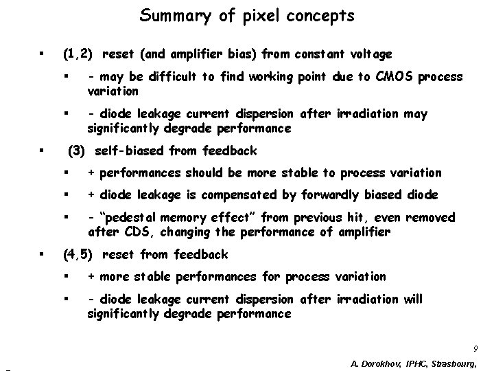
Pixel designs § Standard and Radiation tolerant nwell diode designs § Different schematic concepts: 1. Reset diode and standard amplifier (like in Mimosa 8) 2. Reset diode and amplifier with improved load 3. Continuously biased (self-biased) from feedback and amplifier with improved load (like in Mimisa 15 test structures and Mimosa 16) 4. Reset diode from feedback, time variant feedback, amplifier with improved load (similar to Mimosa 1819 test structures) 5. Reset diode from feedback, time variant feedback, standard amplifier § CDS with clamping capacitance A. Dorokhov, IPHC, Strasbourg,
Nwell diode designs § Size from 3. 4 um x 3. 4 um - to 4. 5 um x 4. 5 um § Standard with thick oxide around Nwell § Radiation tolerant with thin gate oxide around Nwell A. Dorokhov, IPHC, Strasbourg,
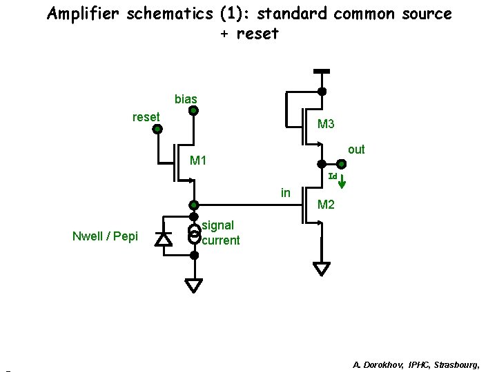
Amplifier schematics (1): standard common source + reset bias reset M 3 out M 1 Id in Nwell / Pepi M 2 signal current A. Dorokhov, IPHC, Strasbourg,
Amplifier schematics (2): improved common source + reset M 4 bias reset M 3 out M 1 Id in Nwell / Pepi M 2 signal current A. Dorokhov, IPHC, Strasbourg,
Amplifier schematics (3): improved common source + continuously biased from feedback (self-biased) M 4 M 5 Low-pass filter out M 3 feedback Pdiff / Nwell / Pepi out Id in M 2 signal current A. Dorokhov, IPHC, Strasbourg,
Amplifier schematics (4): improved common source + reset from feedback (time-variant feedback) reset M 4 M 5 M 3 out Time-variant feedback Id in Nwell / Pepi M 2 signal current A. Dorokhov, IPHC, Strasbourg,
Amplifier schematics (5): standard common source + reset from feedback (time-variant feedback) reset M 4 M 3 out Time-variant feedback Id in Nwell / Pepi M 2 signal current A. Dorokhov, IPHC, Strasbourg,
Summary of pixel concepts § § § (1, 2) reset (and amplifier bias) from constant voltage § - may be difficult to find working point due to CMOS process variation § - diode leakage current dispersion after irradiation may significantly degrade performance (3) self-biased from feedback § + performances should be more stable to process variation § + diode leakage is compensated by forwardly biased diode § - “pedestal memory effect” from previous hit, even removed after CDS, changing the performance of amplifier (4, 5) reset from feedback § + more stable performances for process variation § - diode leakage current dispersion after irradiation will significantly degrade performance 9 A. Dorokhov, IPHC, Strasbourg,
Simulation results Simulation with Spectre, parasitic capacitances for diodes, metal lines and transistors are extracted by Frédéric Morel 10 A. Dorokhov, IPHC, Strasbourg,
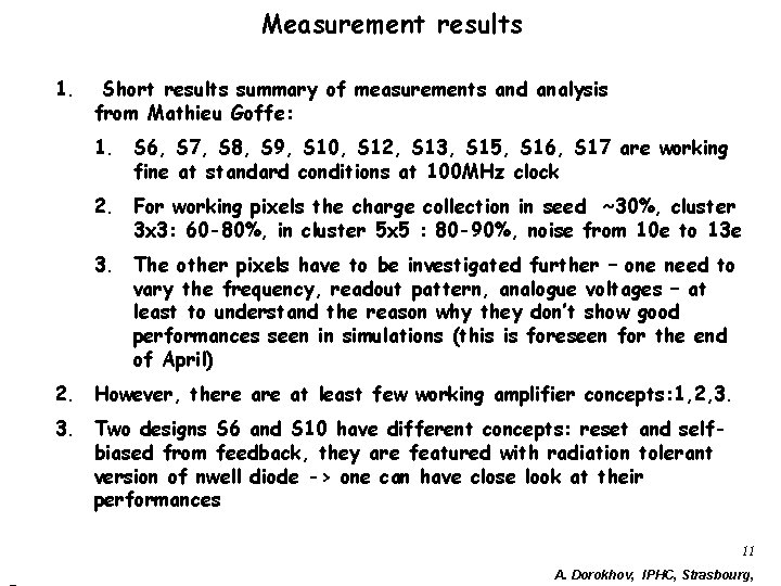
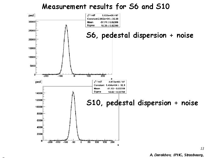
Measurement results 1. Short results summary of measurements and analysis from Mathieu Goffe: 1. S 6, S 7, S 8, S 9, S 10, S 12, S 13, S 15, S 16, S 17 are working fine at standard conditions at 100 MHz clock 2. For working pixels the charge collection in seed ~30%, cluster 3 x 3: 60 -80%, in cluster 5 x 5 : 80 -90%, noise from 10 e to 13 e 3. The other pixels have to be investigated further – one need to vary the frequency, readout pattern, analogue voltages – at least to understand the reason why they don’t show good performances seen in simulations (this is foreseen for the end of April) 2. However, there at least few working amplifier concepts: 1, 2, 3. 3. Two designs S 6 and S 10 have different concepts: reset and selfbiased from feedback, they are featured with radiation tolerant version of nwell diode -> one can have close look at their performances 11 A. Dorokhov, IPHC, Strasbourg,
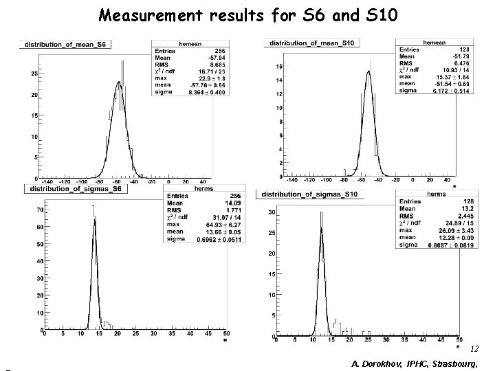
Measurement results for S 6 and S 10 12 A. Dorokhov, IPHC, Strasbourg,
Measurement results for S 6 and S 10 S 6, pedestal dispersion + noise S 10, pedestal dispersion + noise 13 A. Dorokhov, IPHC, Strasbourg,
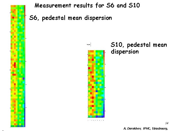
Measurement results for S 6 and S 10 S 6, pedestal mean dispersion S 10, pedestal mean dispersion 14 A. Dorokhov, IPHC, Strasbourg,
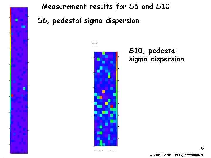
Measurement results for S 6 and S 10 S 6, pedestal sigma dispersion S 10, pedestal sigma dispersion 15 A. Dorokhov, IPHC, Strasbourg,
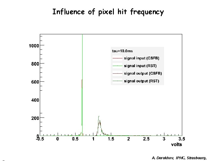
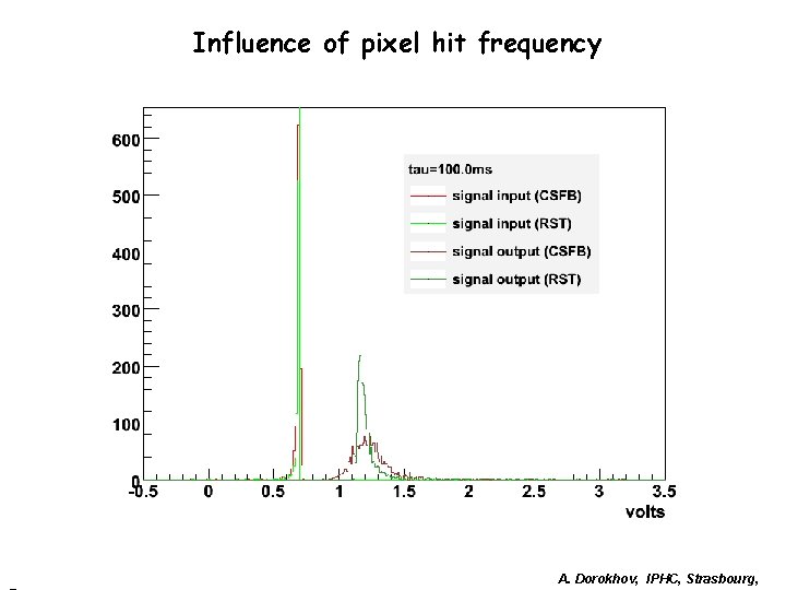
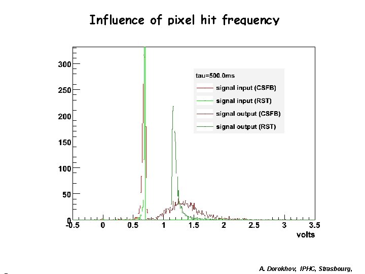
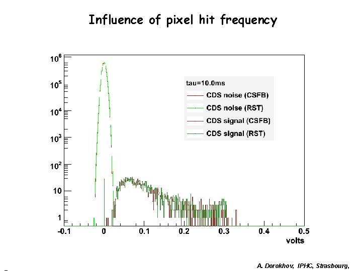
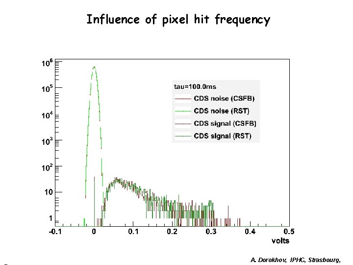
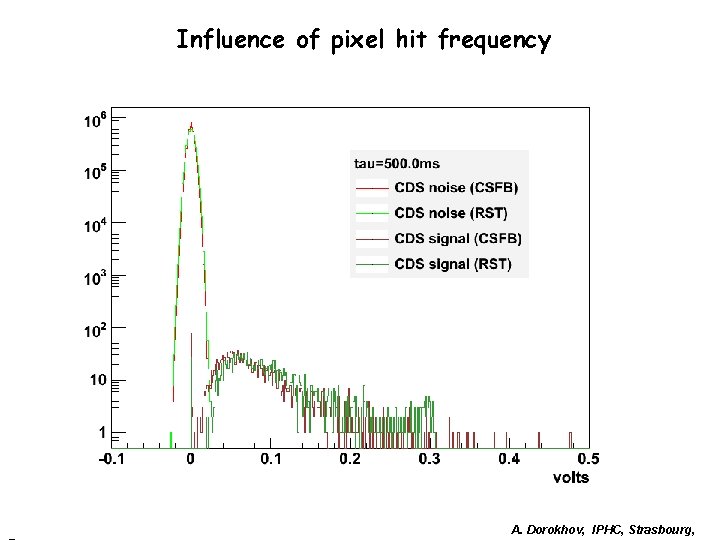
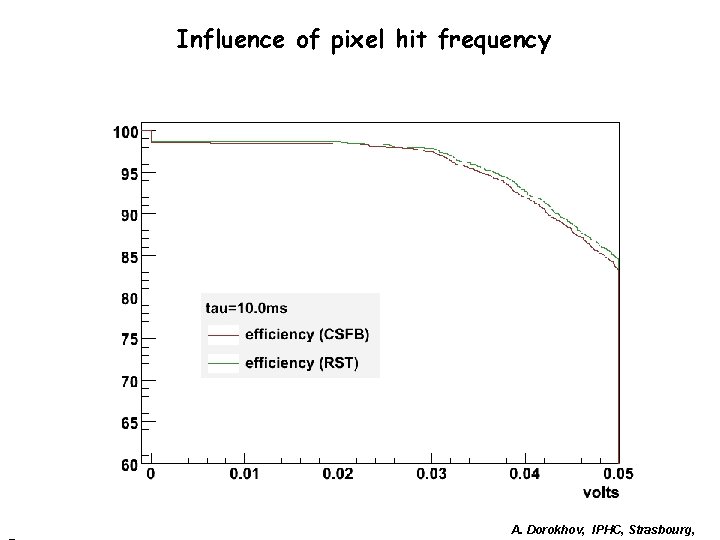
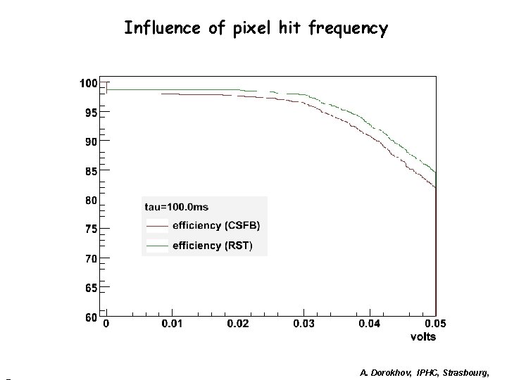
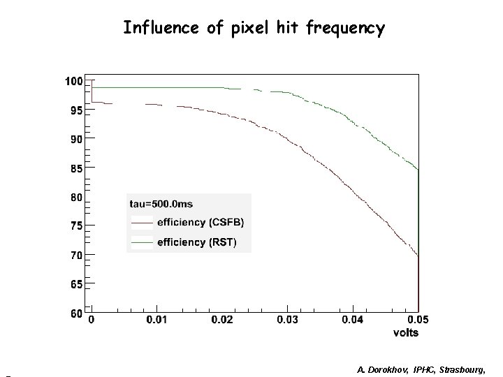
Influence of pixel hit frequency 1. Designs with reset are not sensitive to “memory” effect – charge is always restored to a fixed value 2. Continuously biased diode will store some fraction of charge from previously incident particle, even if the signal completely reconstructed after CDS, there is “internal memory” in the nwell diode -> charge is accumulated and circuit can go to non-linear state A. Dorokhov, IPHC, Strasbourg,
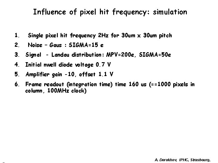
Influence of pixel hit frequency: simulation 1. Single pixel hit frequency 2 Hz for 30 um x 30 um pitch 2. Noise – Gaus : SIGMA=15 e 3. Signal - Landau distribution: MPV=200 e, SIGMA=50 e 4. Initial nwell diode voltage 0. 7 V 5. Amplifier gain -10, offset 1. 1 V 6. Frame readout (integration time) time 160 us (==1000 pixels in column, 100 MHz clock) A. Dorokhov, IPHC, Strasbourg,
Influence of pixel hit frequency A. Dorokhov, IPHC, Strasbourg,
Influence of pixel hit frequency A. Dorokhov, IPHC, Strasbourg,
Influence of pixel hit frequency A. Dorokhov, IPHC, Strasbourg,
Influence of pixel hit frequency A. Dorokhov, IPHC, Strasbourg,
Influence of pixel hit frequency A. Dorokhov, IPHC, Strasbourg,
Influence of pixel hit frequency A. Dorokhov, IPHC, Strasbourg,
Influence of pixel hit frequency A. Dorokhov, IPHC, Strasbourg,
Influence of pixel hit frequency A. Dorokhov, IPHC, Strasbourg,
Influence of pixel hit frequency A. Dorokhov, IPHC, Strasbourg,
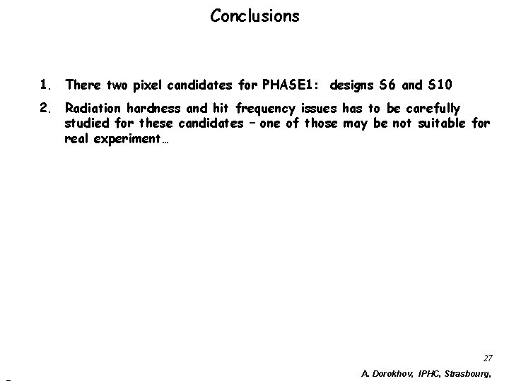
Conclusions 1. There two pixel candidates for PHASE 1: designs S 6 and S 10 2. Radiation hardness and hit frequency issues has to be carefully studied for these candidates – one of those may be not suitable for real experiment… 27 A. Dorokhov, IPHC, Strasbourg,