
Deployment of MPLS VPN in Large ISP Networks


- Slides: 23
Deployment of MPLS VPN in Large ISP Networks Luyuan Fang IP Network Architecture AT&T 1
Outline n n n Requirements Associated with the Deployment of MPLS VPN in an ISP Network Strategy for the Incremental Deployment of MPLS VPN - Implementation Options Carrier’s Carrier and Inter-provider Backbone VPN Deployment Issues and Future Work NANOG 21, February 2001, Atlanta 2
Requirements Associated with the Deployment of MPLS VPN in an ISP Network n Preservation of network integrity n n the new service features must not entail the risk of degrading the reliability and availability of the existing network Scalability n n Scaleable to large number of provider-based VPN Network of network VPN services n n n Carrier’s Carrier and Inter-provider backbone VPN Satisfaction of customers’ security requirements Proactive management and fast restoration in case of failure NANOG 21, February 2001, Atlanta 3
Strategy for the Incremental Deployment of MPLS VPN n n n The steps described here are simplified for illustrative purposes The steps may not be followed in the exact order proposed in a production environment Different steps may also be taken simultaneously, depending on the business needs, feature availability, and interoperability NANOG 21, February 2001, Atlanta 4
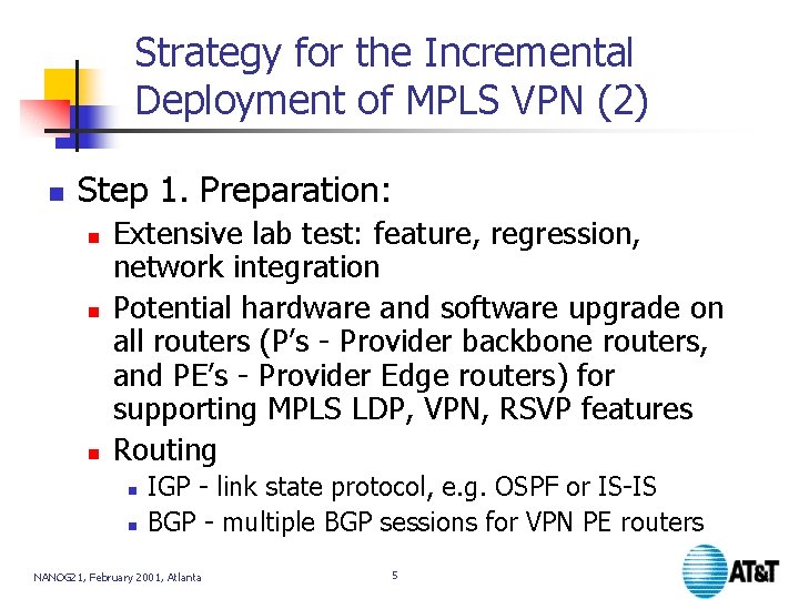
Strategy for the Incremental Deployment of MPLS VPN (2) n Step 1. Preparation: n n n Extensive lab test: feature, regression, network integration Potential hardware and software upgrade on all routers (P’s - Provider backbone routers, and PE’s - Provider Edge routers) for supporting MPLS LDP, VPN, RSVP features Routing n n IGP - link state protocol, e. g. OSPF or IS-IS BGP - multiple BGP sessions for VPN PE routers NANOG 21, February 2001, Atlanta 5
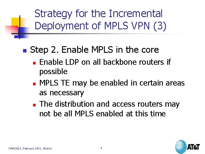
Strategy for the Incremental Deployment of MPLS VPN (3) n Step 2. Enable MPLS in the core n n n Enable LDP on all backbone routers if possible MPLS TE may be enabled in certain areas as necessary The distribution and access routers may not be all MPLS enabled at this time NANOG 21, February 2001, Atlanta 6
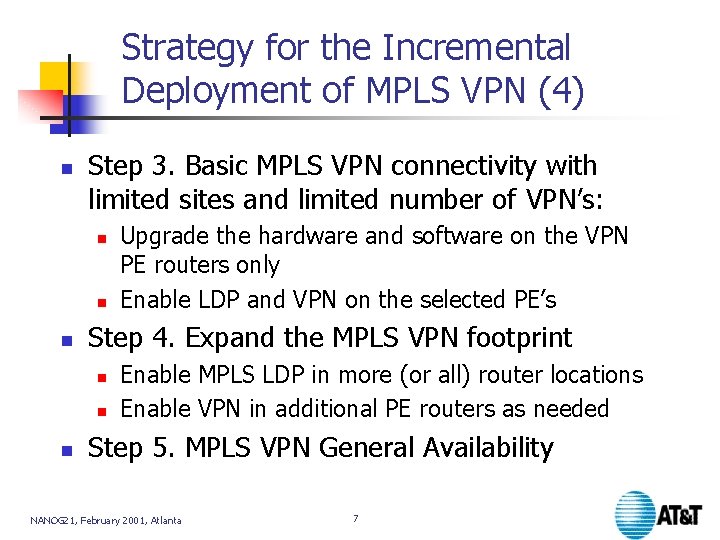
Strategy for the Incremental Deployment of MPLS VPN (4) n Step 3. Basic MPLS VPN connectivity with limited sites and limited number of VPN’s: n n n Step 4. Expand the MPLS VPN footprint n n n Upgrade the hardware and software on the VPN PE routers only Enable LDP and VPN on the selected PE’s Enable MPLS LDP in more (or all) router locations Enable VPN in additional PE routers as needed Step 5. MPLS VPN General Availability NANOG 21, February 2001, Atlanta 7
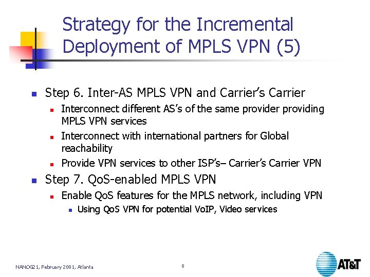
Strategy for the Incremental Deployment of MPLS VPN (5) n Step 6. Inter-AS MPLS VPN and Carrier’s Carrier n n Interconnect different AS’s of the same provider providing MPLS VPN services Interconnect with international partners for Global reachability Provide VPN services to other ISP’s– Carrier’s Carrier VPN Step 7. Qo. S-enabled MPLS VPN n Enable Qo. S features for the MPLS network, including VPN n Using Qo. S VPN for potential Vo. IP, Video services NANOG 21, February 2001, Atlanta 8
MPLS VPN - Implementation Options 9
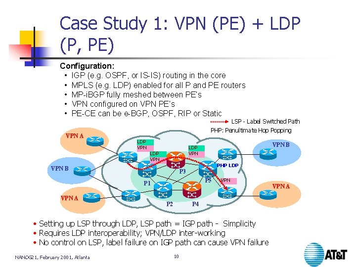
Case Study 1: VPN (PE) + LDP (P, PE) Configuration: • IGP (e. g. OSPF, or IS-IS) routing in the core • MPLS (e. g. LDP) enabled for all P and PE routers • MP-i. BGP fully meshed between PE’s • VPN configured on VPN PE’s • PE-CE can be e-BGP, OSPF, RIP or Static VPN A LSP - Label Switched Path PHP: Penultimate Hop Popping LDP VPN PHP LDP VPN B P 3 P 5 P 1 VPN A VPN B LDP VPN P 2 VPN P 4 • Setting up LSP through LDP, LSP path = IGP path - Simplicity • Requires LDP interoperability; VPN/LDP inter-working • No control on LSP, label failure on IGP path can cause VPN failure NANOG 21, February 2001, Atlanta 10 VPN A
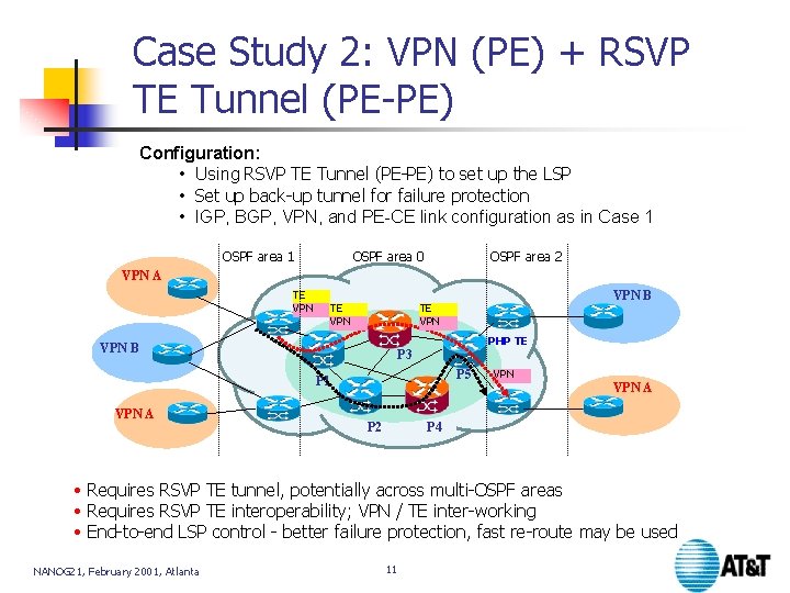
Case Study 2: VPN (PE) + RSVP TE Tunnel (PE-PE) Configuration: • Using RSVP TE Tunnel (PE-PE) to set up the LSP • Set up back-up tunnel for failure protection • IGP, BGP, VPN, and PE-CE link configuration as in Case 1 OSPF area 0 OSPF area 2 VPN A TE VPN PHP TE VPN B P 3 P 5 P 1 VPN A VPN B TE VPN P 2 VPN A P 4 • Requires RSVP TE tunnel, potentially across multi-OSPF areas • Requires RSVP TE interoperability; VPN / TE inter-working • End-to-end LSP control - better failure protection, fast re-route may be used NANOG 21, February 2001, Atlanta 11
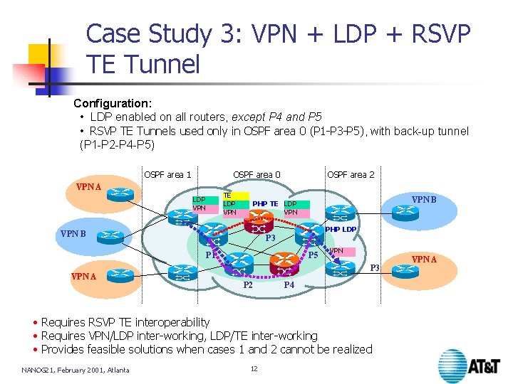
Case Study 3: VPN + LDP + RSVP TE Tunnel Configuration: • LDP enabled on all routers, except P 4 and P 5 • RSVP TE Tunnels used only in OSPF area 0 (P 1 -P 3 -P 5), with back-up tunnel (P 1 -P 2 -P 4 -P 5) OSPF area 1 OSPF area 0 VPN A TE LDP VPN OSPF area 2 PHP LDP VPN B P 3 P 1 VPN A VPN B PHP TE LDP VPN P 5 VPN P 3 P 2 P 4 • Requires RSVP TE interoperability • Requires VPN/LDP inter-working, LDP/TE inter-working • Provides feasible solutions when cases 1 and 2 cannot be realized NANOG 21, February 2001, Atlanta 12 VPN A
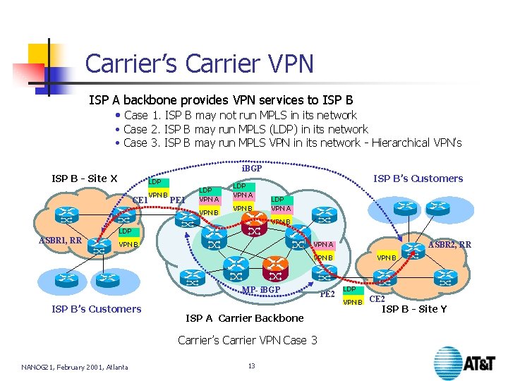
Carrier’s Carrier VPN ISP A backbone provides VPN services to ISP B • Case 1. ISP B may not run MPLS in its network • Case 2. ISP B may run MPLS (LDP) in its network • Case 3. ISP B may run MPLS VPN in its network - Hierarchical VPN’s i. BGP ISP B - Site X LDP CE 1 VPN B PE 1 LDP VPN A VPN B ISP B’s Customers LDP VPN A VPN B LDP ASBR 1, RR VPN A VPN B ASBR 2, RR VPN B MP- i. BGP ISP B’s Customers ISP A Carrier Backbone Carrier’s Carrier VPN Case 3 NANOG 21, February 2001, Atlanta 13 PE 2 VPN B LDP VPN B CE 2 ISP B - Site Y
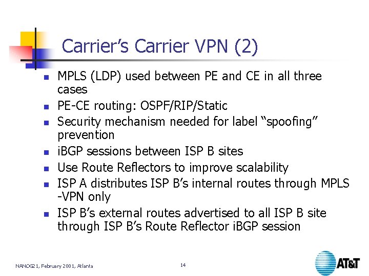
Carrier’s Carrier VPN (2) n n n n MPLS (LDP) used between PE and CE in all three cases PE-CE routing: OSPF/RIP/Static Security mechanism needed for label “spoofing” prevention i. BGP sessions between ISP B sites Use Route Reflectors to improve scalability ISP A distributes ISP B’s internal routes through MPLS -VPN only ISP B’s external routes advertised to all ISP B site through ISP B’s Route Reflector i. BGP session NANOG 21, February 2001, Atlanta 14
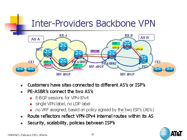
Inter-Providers Backbone VPN RR-A AS A RR-B AS B LDP PE 1 CE 1 VPN AB LDP VPN A PE-ASBR 1 LDP VPN A n n CE 2 PE 2 MP- i. BGP Customers have sites connected to different AS’s or ISP’s PE-ASBR’s connect the two AS’s n n VPN B PE-ASBR 2 MP- e. BGP MP- i. BGP n VPN B E-BGP sessions for VPN-IPv 4 single VPN label, no LDP label no VRF assigned, based on policy agreed by the two ISP’s (AS’s) Route reflectors reflect VPN-IPv 4 internal routes within its AS Security, scalability, policies between ISP’s NANOG 21, February 2001, Atlanta 15
MPLS VPN Deployment Issues n MPLS Feature availability n n n Multi-vendor inter-operability n n VPN, LDP, RSVP, CR-LDP: individually, and Interworking amongst subsets of these Coping with reality of feature availability Required in an heterogeneous IP network Deployment strategy n n n Partially enable MPLS vs. Fully enable MPLS in the entire IP backbone TE tunnels, use only as needed vs. fully meshed Qo. S VPN: map VPN into guaranteed bandwidth tunnels with class of service NANOG 21, February 2001, Atlanta 16
MPLS VPN Deployment Issues (2) n Scalability n n Load sharing between PE-CE links n n The use of Route Reflectors Performance impact on PE’s needs to be measured Carrier of Carriers and Inter-AS backbone Assign different RDs to different sites vs. single RD for each VPN Security n n One VPN’s route does not exist in other nonconnected VPN’s VRF or the global routing table FR/ATM equivalent security - more study needed NANOG 21, February 2001, Atlanta 17
MPLS VPN Network Management n Available MIBs today n n LSR MIB, LDP MIB, VPN MIB, MBGP MIB, RSVP TE MIB, FTN MIB, … Configuration and Provisioning n Auto-provisioning tools needed for large scale VPN deployment NANOG 21, February 2001, Atlanta 18
MPLS VPN Network Management (2) n Performance n n n All MPLS features impact on performance, including basic VPN on PE routers, and need to be studied More study needed for VPN supporting Qo. S Network performance: delay, jitter, loss, throughput, availability Element performance: utilization Security management n Authentication, control access, monitoring NANOG 21, February 2001, Atlanta 19
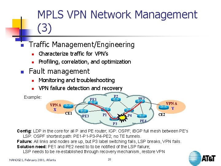
MPLS VPN Network Management (3) n Traffic Management/Engineering n n n Characterize traffic for VPN’s Profiling, correlation, and optimization Fault management n n Monitoring and troubleshooting VPN failure detection and recovery Example: P 2 PE 1 VPN A X CE 1 PE 3 PE 2 VPN A Y P 1 CE 2 P 4 P 3 PE 4 Config: LDP in the core for all P and PE router; IGP: OSPF; i. BGP full mesh between PE’s LSP: OSPF shortest path: PE 1 -P 3 -P 4 -PE 2; no TE tunnels. Failure: All links and nodes are up, but P 3 label switching fails, LSP breaks, VPN fails. Solution need: PE 1 and PE 2 need to to be notified of the LSP failure; LSP needs to be re-established through recovery mechanism, restore VPN NANOG 21, February 2001, Atlanta 20
Summary n Incremental deployment of BGP/MPLS VPN in IP backbone is feasible n n n Implementation alternatives and examples illustrated here are being experimented with through lab testing Deployment Challenges Feature availability Interoperability Manageability NANOG 21, February 2001, Atlanta 21
Summary (2) n Future work n n Resolve open issues on scalability, load sharing, and security Better understand service deployment and management NANOG 21, February 2001, Atlanta 22
Thank You Luyuan Fang Principal Technical Staff Member IP Network Architecture AT&T luyuanfang@att. com 23