Delta Electronics G G Illustrations See figure below

ЧПУ Delta Electronics G-коды. Примеры
![Формат команд G-кодов [Illustrations] See figure below for moving cutters from point A to](http://slidetodoc.com/presentation_image/56a028c4598e0c02802b33f4f3b4577c/image-7.jpg "Формат команд G-кодов [Illustrations] See figure below for moving cutters from point A to")
Формат команд G-кодов [Illustrations] See figure below for moving cutters from point A to point B at fast speed. Expressed in absolute values: G 90 G 00 X 92. Y 35. Expressed in incremental values: G 91 G 00 X 62. Y-25. 7

Формат команд G-кодов G 01: Linear Cutting Command Формат команды: G 01 XˍYˍZˍFˍ XˍYˍZˍ: End point coordinates. Fˍ: Feed rate in unit of mм/мин Command description: This command enables a cutter to linear cut from the current position to a given position at F feed rate. The ending position of the cutting is given by the X, Y, and Z coordinates. The feed rate is set by the F parameter along with the optional Feed Rate of the secondary control panel in unit of mm/ min. 8
![Формат команд G-кодов [Illustrations] Regarding the method of G 01, see figure below for](http://slidetodoc.com/presentation_image/56a028c4598e0c02802b33f4f3b4577c/image-9.jpg "Формат команд G-кодов [Illustrations] Regarding the method of G 01, see figure below for")
Формат команд G-кодов [Illustrations] Regarding the method of G 01, see figure below for milling in direction of +Y from program origin. G 00 G 90 G 54 X 0 Y 0 G 90 G 01 Y 40. 0 F 80 X-60. 0 G 91 Y-20. 0 X 35. 0 Y-20. 0 G 90 X 0 Y 0 The F parameter remains active unless being changed as shown in program codes listed above where the F parameters are omitted in subsequent statements. 9

Формат команд G-кодов G 90: Absolute Coordinate System Command syntax: G 90 Xˍ Yˍ Zˍ [Illustrations] From point 1 of coordinates (X 10, Y 10) to point 2 (X 30, Y 30), the tool moves an actual distance of X 20 and Y 20 as shown in the figure below. O 1000 G 01 G 90 X 10. 0 Y 10. 0 F 500. 0 X 30. 0 Y 30. 0 10

Формат команд G-кодов G 91: Incremental Coordinate System Command Формат команды: G 91 Xˍ Yˍ Zˍ [Illustrations] From point 1 of coordinates (X 10, Y 10) to point 2 (X 20, Y 20) the tool moves an actual distance of X 20 and Y 20 to point (X 30, Y 30) of the actual mechanical coordinates as shown in the figure below. O 1001 G 91 X 10. 0 Y 10. 0 F 500. 0 X 20. 0 Y 20. 0 11

Формат команд G-кодов Example of using G 90 and G 91 commands together: O 0010 G 01 G 90 X 0 Y 0 F 1000 X 40. 0 G 91 Y 20. 0 X-5. 0 Y 5. 0 G 90 X 5. 0 X 0 Y 20. 0 Y 0 M 30

Формат команд G-кодов G 54~G 59: Workpiece Coordinate System Selection Command Формат команды: G 90 G 54 Xˍ Yˍ Zˍ or; G 90 G 55 Xˍ Yˍ Zˍ or; G 90 G 56 Xˍ Yˍ Zˍ or; G 90 G 57 Xˍ Yˍ Zˍ or; G 90 G 58 Xˍ Yˍ Zˍ or; G 90 G 59 Xˍ Yˍ Zˍ A workpiece coordinates system is created by moving the tool from the mechanical origin to the desired program origin (with proper X and Y distance), registering this position data in the workpiece coordinates system setup (G 54~G 59) in the controller OFS group function, and executing the workpiece coordinates system code, then you can set up the workpiece coordinates origin. The system also features a designation function out of 64 sets of expansive workpiece coordinates system options. This is done by assigning values to argument P_ (with valid value range of 1~64) in command G 54. For example, G 54 P 10 X_ Y_ Z_. It means the tenth coordinates system of expanded workpiece coordinates system is used. 13

Формат команд G-кодов Work reference point of G 55 coordinate system , this point is decided based on user’s request. 14

Формат команд G-кодов G 28: Homing to the First Reference Point Формат команды: G 90 G 28 Xˍ Yˍ Zˍ or; G 91 G 28 Xˍ Yˍ Zˍ Xˍ Yˍ Zˍ: Coordinates of reference point Command description: This command instructs the tool to fast move (G 00) from the reference point given by the command to the mechanical origin. It is designed to return to the mechanical origin by moving to the reference point given by the command to avoid any intersection with the workpiece or the machine equipment. 15

Формат команд G-кодов G 90 G 28 Z 50 → Return to mechanical origin from point A through reference point B (Z-axis). M 06 T 02 → Switch to tool 2. 16
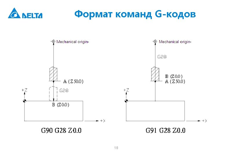
![Формат команд G-кодов [Illustrations] Status of G 90/G 91 differs in the process of](http://slidetodoc.com/presentation_image/56a028c4598e0c02802b33f4f3b4577c/image-17.jpg "Формат команд G-кодов [Illustrations] Status of G 90/G 91 differs in the process of")
Формат команд G-кодов [Illustrations] Status of G 90/G 91 differs in the process of returning to the mechanical origin when command G 28 is executed. See figure below for details. 17

Формат команд G-кодов G 02/G 03: Arc Cutting Command Arcs in the X – Y plane G 17 G 02 (or G 03) Xˍ Yˍ Rˍ Fˍ or G 17 G 02 (or G 03) Xˍ Yˍ Iˍ Jˍ Fˍ You may add parameter Zˍ in the command to spiral move in the X – Y plane. Arcs in the Z – X plane G 18 G 02 (or G 03) Zˍ Xˍ Rˍ Fˍ or G 18 G 02 (or G 03) Zˍ Xˍ Kˍ Iˍ Fˍ You may add parameter Yˍ in the command to spiral move in the Z – X plane. Arcs in the Y – Z plane G 19 G 02 (or G 03) Yˍ Zˍ Rˍ Fˍ or G 19 G 02 (or G 03) Yˍ Zˍ Jˍ Kˍ Fˍ You may add parameter Xˍ in the command to spiral move in the Y – Z plane. 19
 arc cutting. G 03: Counterclockwise (CCW) arc")
Формат команд G-кодов G 02: Clockwise (CW) arc cutting. G 03: Counterclockwise (CCW) arc cutting. X, Y, and Z: Coordinates of the end point in absolute or incremental values determined by command G 90 and G 91. R: Arc radius (expressed in the so-called Radius method). I: The X-axis distance between arc center and starting point. The increment amount from the starting point to arc center. J: The Y-axis distance between arc center and starting point. The increment amount from the starting point to arc center. K: The Z-axis distance between arc center and starting point. The increment amount from the starting point to arc center. (The I, J, and K expression is also known as the Center method. ) F: The cut feeding speed in unit of mм/мин. 20

Формат команд G-кодов Command description: G 02 or G 03 is the arc cutting command. The arc cutting direction (G 02 or G 03) for a three-dimensional workpiece in individual planes is shown in Figure 1. The cutting direction is defined by the right hand coordinate system. Look against the positive direction of the plane's vertical axis; G 02 is for clockwise direction while G 03 is for counterclockwise. 21

G 02/G 03: круговая интерполяция Radius method: R is the radius of the arc and shows in radius value. This method represents an arc by its starting point, ending point, and arc radius. There are two equivalent arcs in a circle as shown in the figure below. For the positive R value, it is an arc of central angle ≤ 180° and an arc of central angle > 180° for the negative R value. β > 180° -> the B arc with negative R α ≤ 180° -> the A arc with positive R In the figure above if R = 50 mm and the absolute coordinates of the end point are (100. 0, 80. 0), then (1) the arc of central angle > 180° (path B) can be expressed as "G 90 G 03 X 100. 0 Y 80. 0 R-50. 0 F 80" and; (2) The arc of central angle ≤ 180° (path A) can be expressed as "G 90 G 03 X 100. 0 Y 80. 0 R 50. 0 F 80" 22

G 02/G 03: круговая интерполяция Center method: Here parameters I, J, and K define the relative distance from the arc start point to the arc center (the end point). That is, the increments from the start point to the center in X, Y, and Z directions respectively. The arc motion expressed in the radius or center method can be used in program coding for selecting conditions. 23

G 02/G 03: круговая интерполяция To cut milling a sphere you can use the center but not the radius method. Generating a sphere by connecting two semi-spheres bears too large a roundness deviation to be acceptable. The command syntax for cut milling a sphere as shown in the figure "G 02 I-50. 0". 24

Формат команд G-кодов Use of commands G 01, G 02, and G 03 is illustrated in the figure below. Here is the tool cut milling from program origin upward along the shape. O 0100 G 90 G 54 X 0 Y 0 S 500 M 3 G 90 G 01 Y 15. 0 F 80 G 02 X 41. 0 Y 40. 0 R 41. 0 G 91 G 01 X 40. 0 G 02 X 10. 0 Y-10. 0 R 10. 0 G 01 Y-20. 0 X-15. 0 Y-10. 0 X-20. G 90 G 03 X 20. 0 R 18. 0 G 01 X 0. 0 =>program origin → A => A → B => B → C => C → D => D → E => E → F => F → G => G → H => H → program origin 26

Формат команд G-кодов G 04: Pause Command Формат команды: G 04 Xˍ or G 04 Pˍ [Illustrations] G 04 X 1. 5 or. G 04 P 1500 Both commands cause a pause span during program execution for 1. 5 seconds. 27

Формат команд G-кодов G 10/G 11: Data Entry Setup and Cancel Формат команды: G 10 L 2 Pˍ Xˍ Yˍ Zˍ G 10 L 10 Pˍ Rˍ: Tool length compensation G 10 L 11 Pˍ Rˍ: Tool length wear compensation G 10 L 12 Pˍ Rˍ: Tool radius compensation G 10 L 13 Pˍ Rˍ: Tool radius wear compensation G 10 L 20 Pˍ Xˍ Yˍ Zˍ: Expansive workpiece coordinate system entry In absolute status(G 90): the G 10 command is the absolute input. In incremental status(G 91): the G 10 command input the value in incremental way. 28
![Формат команд G-кодов [Illustrations] G 10 L 10 P 1 R-300. 0 or G](http://slidetodoc.com/presentation_image/56a028c4598e0c02802b33f4f3b4577c/image-29.jpg "Формат команд G-кодов [Illustrations] G 10 L 10 P 1 R-300. 0 or G")
Формат команд G-кодов [Illustrations] G 10 L 10 P 1 R-300. 0 or G 10 L 10 P 2 R-100. 0 Set length compensation value of Tool 1 to H-300. 0 and H-100. 0 for Tool 2. P: Compensation number or workpiece coordinate number R: Tool compensation value The examples of absolute and incremental status are as followings: G 90 G 10 L 10 P 1 R-300. 0 Input the data to H-300. 0 of Tool 1 in absolute way. G 91 G 10 L 10 P 1 R-100. 0 Input the data to Tool 1 and add H-100. 0 to it in incremental way. 29

Формат команд G-кодов G 17/G 18/G 19: Plane Designation Command Формат команды: X - Y plane G 17 {G 01~G 03} Xˍ Yˍ{Iˍ Jˍ or Rˍ}Fˍ Z - X plane G 18 {G 01~G 03} Zˍ Xˍ{Kˍ Iˍ or Rˍ}Fˍ Y - Z plane G 19 {G 01~G 03} Yˍ Zˍ{Jˍ Kˍ or Rˍ}Fˍ 30

Формат команд G-кодов G 31: Skip Function Command Формат команды: G 31 Xˍ Yˍ Zˍ Fˍ [Illustration 1] G 90 G 00 X 0 Y 0 G 01 G 31 X 80. 0 F 500. 0 Y 40. 0 [Illustration 1] G 90 G 00 X 0 Y 0; G 01 G 90 G 31 X 50. 0 F 150. 0; X 80. 0 Y 40. 0; 31

Формат команд G-кодов G 43/G 44: Tool Length Compensation Command Формат команды: G 43 Zˍ Hˍ G 44 Zˍ Hˍ G 43: Tool length positive compensation. For positive tool length the tool axis moves in the positive direction. G 44: Tool length negative compensation. For negative tool length the tool axis moves in the negative direction. G 49: Tool Length Compensation Cancelling Command Формат команды: G 49
![Формат команд G-кодов [Illustrations] Tool length compensation setup](http://slidetodoc.com/presentation_image/56a028c4598e0c02802b33f4f3b4577c/image-33.jpg "Формат команд G-кодов [Illustrations] Tool length compensation setup")
Формат команд G-кодов [Illustrations] Tool length compensation setup

Формат команд G-кодов G 50 /G 51: Scaling Up/Down Command/Cancelling Command指令格式: Формат команды: G 51 Xˍ Yˍ Zˍ Pˍ Xˍ Yˍ Zˍ: Coordinates center for scaling Pˍ0: Scaling ratio 34

Формат команд G-кодов G 53: Mechanical Coordinate System Setup Command Формат команды: G 53 Xˍ Yˍ Zˍ: Position of actually arrived mechanical coordinates Command description: Coordinates X, Y, and Z are the actual ending point in mechanical coordinates system specified by the program coordinates. Machine suppliers use this command to set up the tool replacement position with the reference point given in mechanical coordinates. Note: (1) Command G 53 functions only at G 90 status. It is ignored in G 91 mode. However, a status command contained in the same statement of G 53, G 00/G 01 or G 90/G 91, changes the status and affects the motion status of the next node. (2) If the statement containing command G 53 also contains a specific axial command, then the axis moves to a specified point. Otherwise, there is no position command. (3) If both commands G 53 and G 28 are set in the same statement, the one read later becomes active. When command G 53 is active, the motion position refers to the mechanical coordinates. If command G 28 is active, then the absolute coordinates are referred to. 35
 A correct specified coordinate is needed in G 53 Формат")
Формат команд G-кодов (4) A correct specified coordinate is needed in G 53 Формат команды. G 53 has to connect to the specified coordinate. Any other G command is not allowed to insert in the single node command so as to prevent the incorrectness of the motion command. For example, G 90 G 00 G 53 X 10. 0 Y 10. 0 Z-20. 0 ---------(Correct command combination) G 90 G 53 G 00 X 10. 0 Y 10. 0 Z-20. 0 --------(Incorrect command combination) Example 1. G 91 G 53 X 150. Y-150. X-30. Y-30. →This command is ignored. →This command is changed to incremental motion mode. Example 2. G 90 G 53 X 50. Y-50. Z 0. → Move to X 50. Y-50. Z 0. in actual mechanical coordinates. Example 3. G 1 G 53 X 100. Y-100. F 1000 X 50. Y 50. → This command executes in G 00 status. → The system moves in G 01 F 1000 motion status. 36

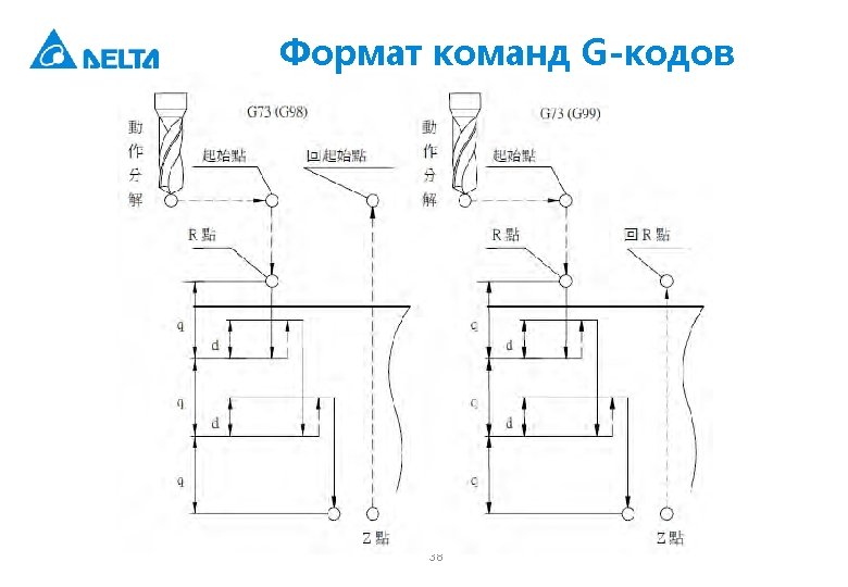
Формат команд G-кодов G 73: Peck Drilling Cycle Command Формат команды: G 73 Xˍ Yˍ Zˍ Rˍ Qˍ Fˍ Kˍ Dˍ Xˍ Yˍ: Ending position of single step Zˍ: Bottom of hole to be drilled Rˍ: Initial safety height Qˍ: Depth of each peck drilling Fˍ: Feed rate Kˍ: Number of cutting loops Dˍ: Amount of retraction d after each cut Command description: This command sets the machine to retreat a constant distance "d“ after drilling a distance (depth) of "Q" and keeps on drilling to the desired hole depth of "Z". The back-and-forth intermittent Z-axis feeding enables easier chip dispelling during drilling deep hole. 37
![Формат команд G-кодов [Illustrations] M 03 S 1000; G 17 G 90 G 00](http://slidetodoc.com/presentation_image/56a028c4598e0c02802b33f4f3b4577c/image-39.jpg "Формат команд G-кодов [Illustrations] M 03 S 1000; G 17 G 90 G 00")
Формат команд G-кодов [Illustrations] M 03 S 1000; G 17 G 90 G 00 G 54 X 0. Y 0. ; G 00 Z 100. ; G 99 G 73 X 0. Y 0. Z-30. R 10. Q 4. K 1 F 100. --- (1) X-15. ; ---------------- (2) X-30. ; ---------------- (3) X-30. Y 15. ; -------------(4) G 80 G 91 G 28 X 0. Y 0. Z 0. ; M 05; 39
![Формат команд G-кодов G 80: Cycle Cancelling Command Формат команды: G 80 [Illustrations] G](http://slidetodoc.com/presentation_image/56a028c4598e0c02802b33f4f3b4577c/image-40.jpg "Формат команд G-кодов G 80: Cycle Cancelling Command Формат команды: G 80 [Illustrations] G")
Формат команд G-кодов G 80: Cycle Cancelling Command Формат команды: G 80 [Illustrations] G 17 G 90 G 00 G 54 X 0. Y 0. ; Z 100. ; G 99 G 73 X 0. Y 0. Z-20. R 10. Q 4. K 1 F 100. ; G 80; -----------(Cancel cycles set by command G 73) G 17 G 90 G 00 G 54 X 0. Y 0. ; Z 100. ; 40

Формат команд G-кодов G 81: Drilling Cycle Command Формат команды: G 81 Xˍ Yˍ Zˍ Rˍ FˍKˍ Xˍ Yˍ: Ending position of single step Zˍ: Cutting depth position Rˍ: Initial safety height Fˍ: Feed rate Kˍ: Number of cycles 41

Формат команд G-кодов G 84: Right Spiral Tapping Cycle Command Формат команды: G 84 Xˍ Yˍ Rˍ Zˍ Pˍ Fˍ Kˍ Xˍ Yˍ: Ending position of single step Zˍ: Cutting depth position Rˍ: Initial safety height Pˍ: Pause time (in the least unit of 1/1000 second), without decimal point. Fˍ: Spiral feed rate Kˍ: Number of cycles 42
![Формат команд G-кодов [Illustrations] G 17 G 90 G 00 G 54 X 0.](http://slidetodoc.com/presentation_image/56a028c4598e0c02802b33f4f3b4577c/image-43.jpg "Формат команд G-кодов [Illustrations] G 17 G 90 G 00 G 54 X 0.")
Формат команд G-кодов [Illustrations] G 17 G 90 G 00 G 54 X 0. Y 0. ; G 00 Z 100. ; M 29 S 1000; G 99 G 84 X 0. Y 0. Z-30. R 10. P 1000 K 1 F 1000. ; -- (1) X-15. ; ------------------- (2) X-30. ; ------------------- (3) X-30. Y 15. ; --------------- (4) M 28; G 80 G 91 G 28 X 0. Y 0. Z 0. ; M 05; 43

Формат команд G-кодов G 98: Return to the Initial Point of the Fixed Cycle Формат команды: G 98 G 8_ Xˍ Yˍ Zˍ Rˍ Fˍ 44

Формат команд G-кодов G 99: Return to the R Point of the Fixed Cycle Формат команды: G 99 G 8_ Xˍ Yˍ Zˍ Rˍ Fˍ 45

- Slides: 46