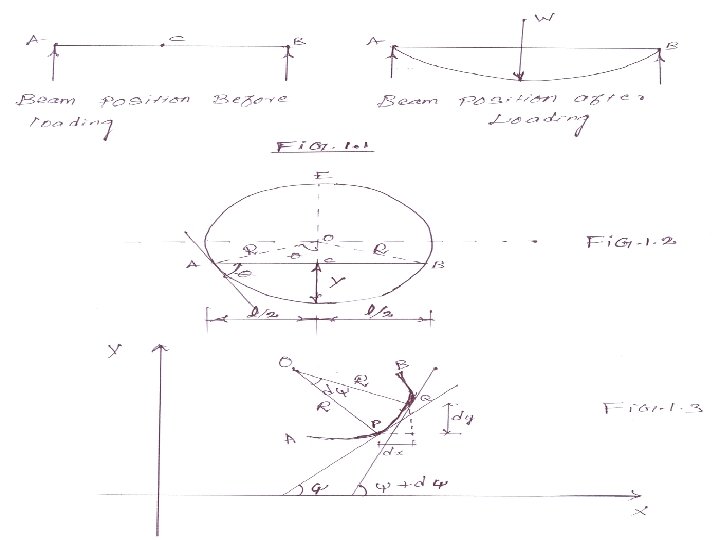
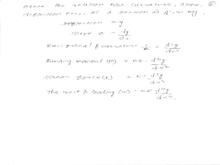
Deflection of beam If the beam carries UDL

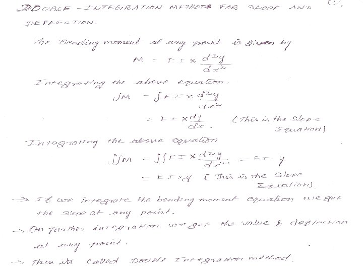
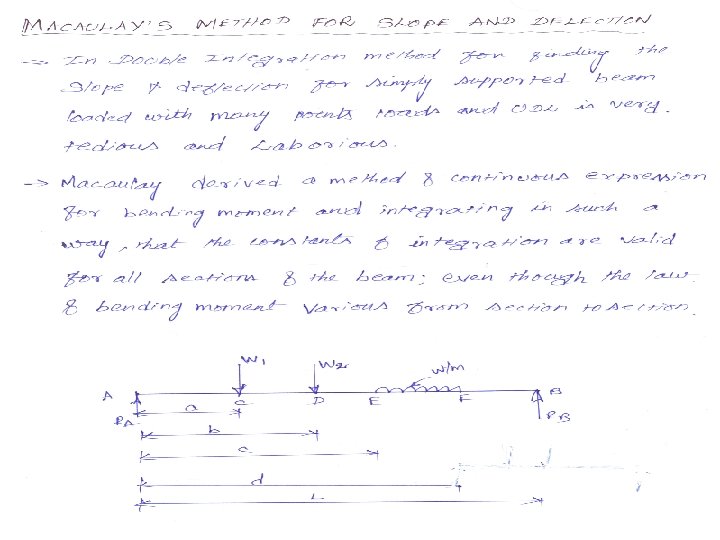
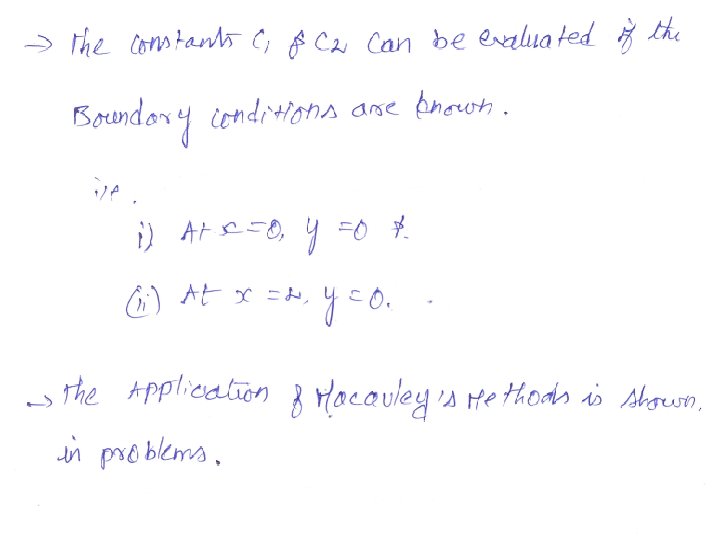
Deflection of beam If the beam carries UDL or point load , the beam is deflected from its original portion Due to the loads acting on the beam , it will be subjected to bending moment SLOPE & DEFLECTION OF THE BEAM MAY BE DETERMINED ANALYTICALLY BY FOLLOWING METHOD I. Double Integration Method II. Macaulay's methods III. Moment area methods IV. Conjugate beam method

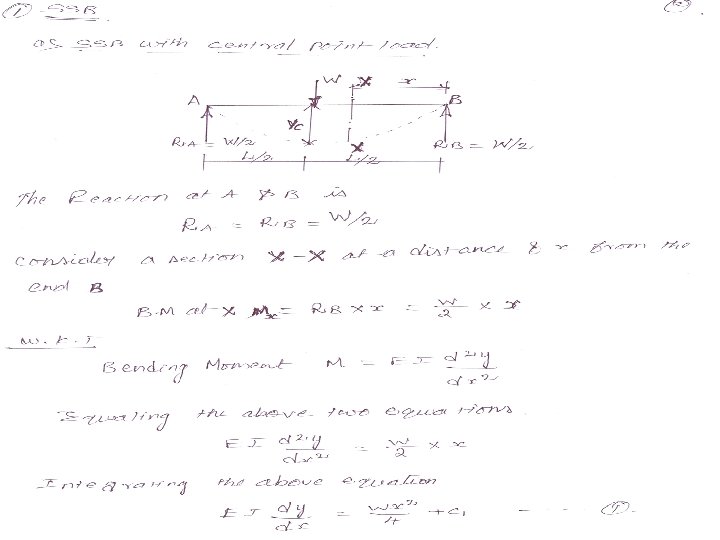
SSB with Point load 1.")
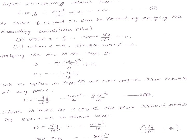
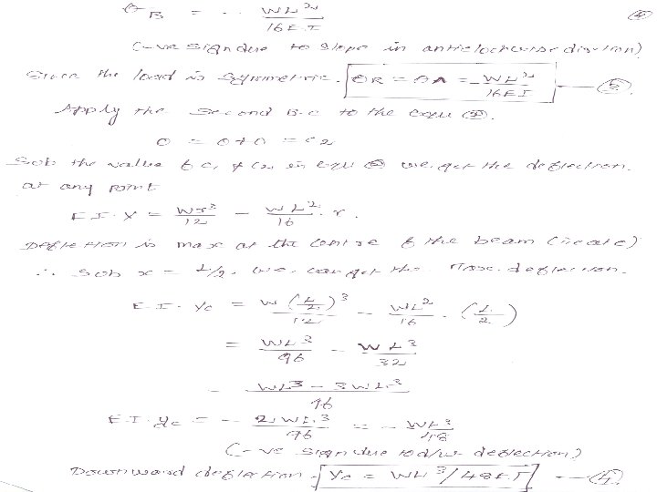
PRACTICE PROBLEMS BY DOUBLE INTEGRATION METHOD SIMPLY SUPPORTED BEAM a)SSB with Point load 1. A beam 6 m long , simply supported ends is carrying a point load of 50 kn at its centre. The M. O. I of the beam is 78× 106 mm 4. If E for the material of the beam is 2. 1× 10⁵ n/ mm 2 , calculate; i) deflection at the centre of the beam & ii) slope at the supports 2. A beam 4 m long simply supported its ends carries a point load W at its centre. If the slope at the ends of the beam is not to exceed 1°, find the deflection at the centre of the beam.
SSB with UDL 1. A beam of length 5 m and")
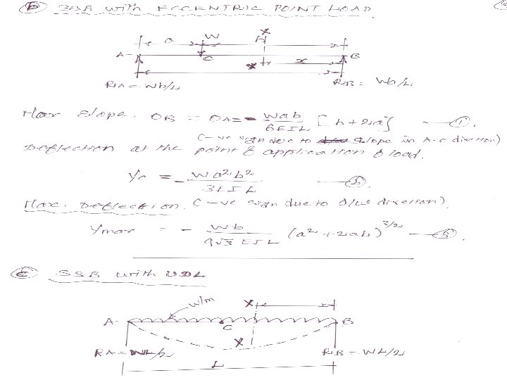
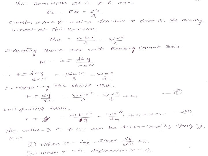
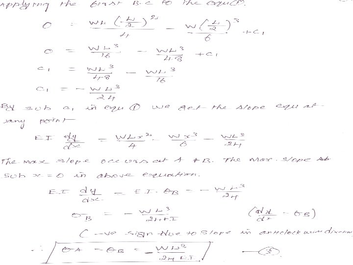
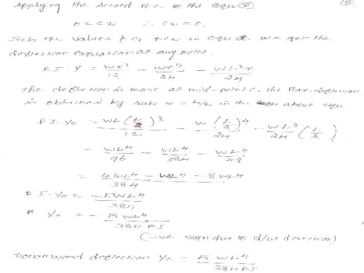
SIMPLY SUPPORTED BEAM b)SSB with UDL 1. A beam of length 5 m and the uniform rectangular section is supported at its ends and carries UDL over the entire length. Calculate the depth of the section if the maximum permissible bending stress is 8 N/mm 2 and central deflection is not to exceed 10 mm. Take E= 1. 2 × 10 4 n/ mm 2 c) SSB with Eccentric load 1.

PRACTICE PROBLEM 1. A horizontal beam is freely supported at its ends 8 m apart & carries UDL of 15 kn/m over the entire span. Find the maximum deflection. Take E = 2× 10⁵ n/ mm 2 & I = 2× 10⁹ n/ mm 2 2. A SSB of 8 m span carries a point load of 10 kn at its centre. It also subjected to a UDL of 1 kn/m over its entire span find the maximum deflection of beam. MOMENT AREA METHOD FOR SLOPE & DEFLECTION 1. SSB WITH POINT LOAD 2. SSB WITH UDL

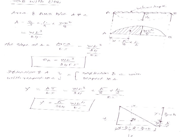

PRACTICE PROBLEM by Moment Area Method. 1. A beam of simply supported 6 m long supported at its ends is carrying a point load of 50 kn at its centre. The moment of inertia of the beam is equal to 1. 2× 10⁸ n/ mm 2. If E for the material of the beam is 2. 1 × 10⁵ n/ mm 2. Calculate the deflection of the centre. 2. A horizontal beam is freely supported at its ends 8 m apart & carries UDL of 15 kn/m over the entire span. Find the maximum deflection. Take E = 2× 10⁵ n/ mm 2 & I = 2× 10⁹ n/ mm 2

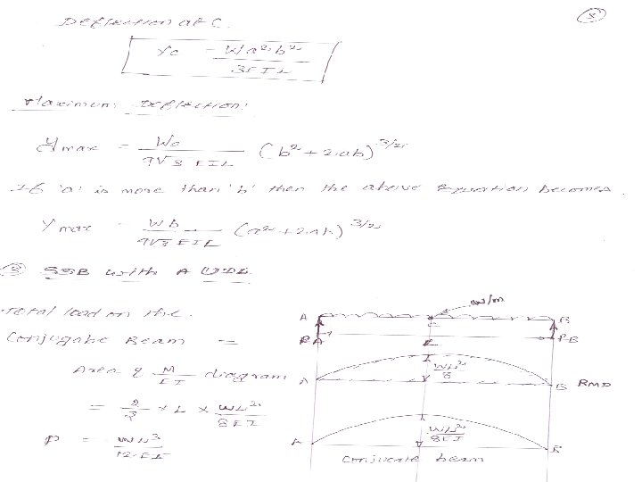
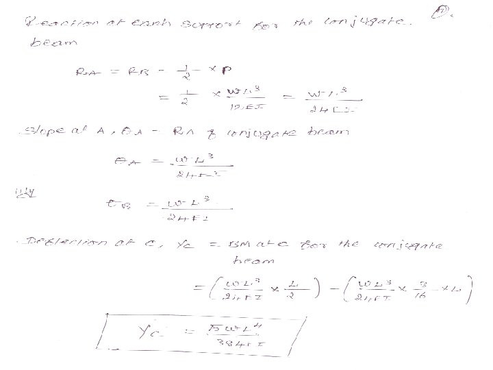
CONJUGATE BEAM METHOD The slope & deflection of such beams can be easily obtained by conjugate beam method. This is a modified form of moment area method. Conjugate beam is an imaginary beam of length equal that of original beam but for which load diagram is M/EI (i. e. , the load at any point on the conjugate beam is equal to the BM at that point divided by EI) The slope & deflection is then found out by the following two theorems which are also called Mohr's theorems. 1. The slope at any section for given beam is equal to the shear force at the corresponding section of the conjugate beam. 2. The deflection at any section for the given beam is equal to the bending moment at the corresponding section of the conjugate beam.


PRACTICE PROBLEM by Conjugate Beam Method 1. A beam of simply supported 6 m long supported at its ends is carrying a point load of 50 kn at its centre. The moment of inertia of the beam is equal to 78× 106 mm 4. If E for the material of the beam is 2. 1 × 10⁵ N/ mm 2. Calculate the deflection of the centre. 2. A simply supported beam of length 8 m is loaded as shown in fig. calculate the slope and deflection at each point by conjugate beam method. Take : E = 2. 1 × 10⁵ N/ mm 2 and I = 78× 106 mm 4 3. A horizontal beam is freely supported at its ends 8 m apart and carries a UDL of 15 KN/m over the entire span. Find the maximum deflection. Take : E = 2 × 10⁵ N/ mm 2 and I = 2× 109 mm 4

UNIVERSITY QUESTIONS 1. A beam AB simply supported at ends is subjected to a point load at C, as shown in fig. using moment area method compute i) the deflection at the point C ii) the slope at point A, B & C Take : E = 2 × 10⁵ N/ mm 2 and I = 6× 108 mm 4 2. A beam ABCD of length 4 m is simply supported at A and D. the beam carries two concentrated loads of 30 KN and 60 KN at points B and C, 2 m and 3 m from the left support A respectively. Determine the slope at supports and maximum deflection. EI is constant throughout.

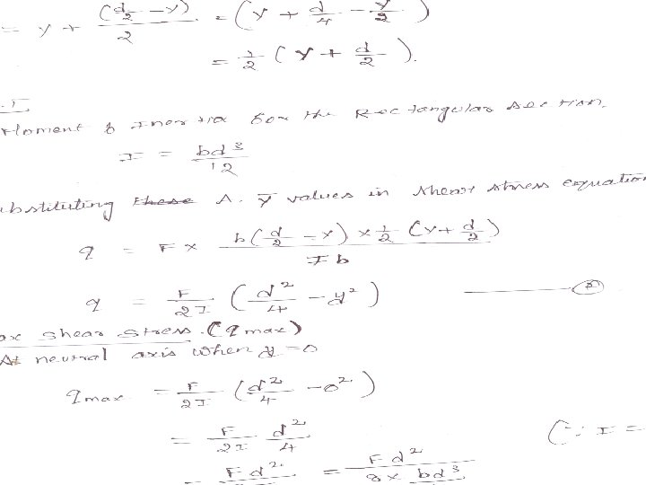
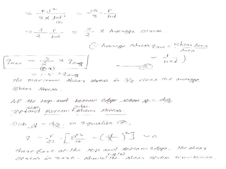
PART –B SHEAR STRESS IN BEAM Theory of simple bending we assumed that no. shear force is acting on the section But in actual practice , under the action of load both shear force & bending moment are in induced. SHEAR STRESS DISTRIBUTION The distribution of the shear stress along the depth of the beam We have to calculate the intensity of shear stress at important sections of a beam & sketch a shear stress distribution diagram. The following section the shear stress distribution to be obtained 1. Rectangular section 2. Circular section 3. I- section 4. T- section 5. Triangular section


PRCTICE PROBLEMS BY RECTANGULAR SECTION 1. A rectangular beam 150 mm wide and 250 mm deep subjected to a maximum shear force of 30 KN. Determine , i) average shear stress ii) maximum shear stress iii) shear stress at a distance 25 mm above the neutral axis 2. A wooden beam 150 mm wide & 300 mm deep & 3 m long is carries UDL of 25 KN/m over the entire length. The beam is simply supported at ends. Determine the maximum shear stress & sketch the shear stress variation along depth of the beam. 3. A simply supported wooden beam of span 1. 3 m having a cross section 150 mm wide by 250 mm deep carries a point load W at the centre. The permissible stress are 7 N/mm 2 in bending & 1 N/mm 2 in shearing. Calculate the safe load W.

4. A beam is subjected to a shear force of 20 KN. The cross section of the beam is of rectangular section 8 cm breath & 12 cm depth. Draw shear stress distribution across the depth of every 2 cm. 5. A timber beam of rectangular section is simply supported at the ends & carries a point load at the centre of the beam. The maximum bending stress is 12 N/mm 2 & maximum shear stress is 1 N/mm 2, find the ratio of the span to the depth.

UNIT – V : TORSION AND SPRINGS PART –A Stresses and deformation in circular (solid and hollow shafts) Stepped shafts Shafts fixed at both ends PART –B Leaf springs Stresses in helical springs Deflection of springs

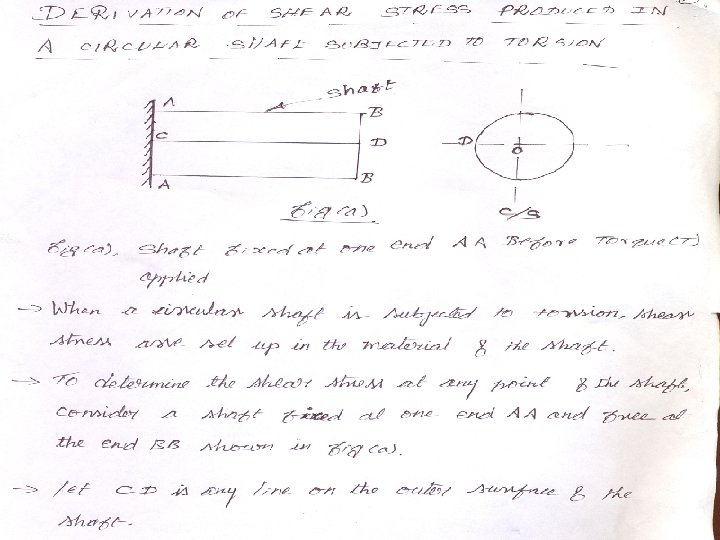
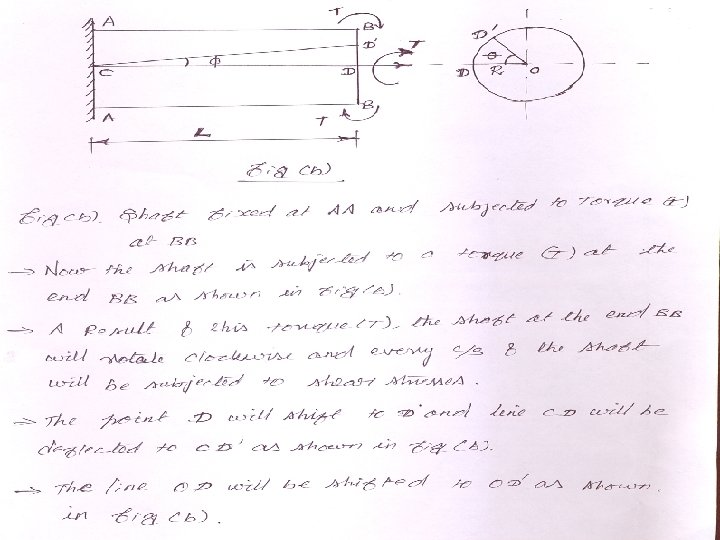
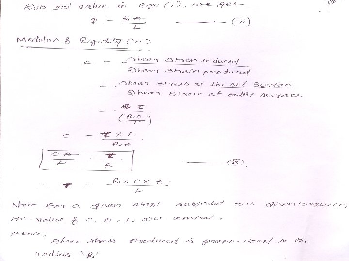
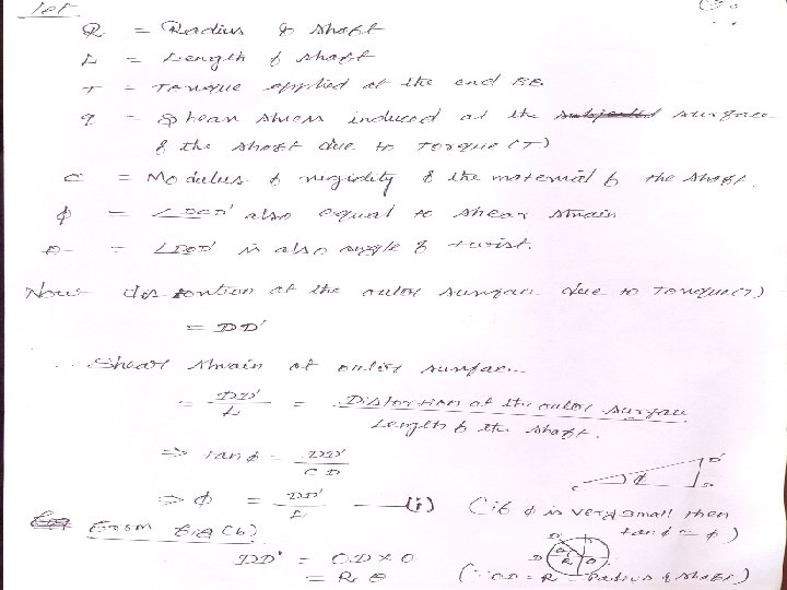
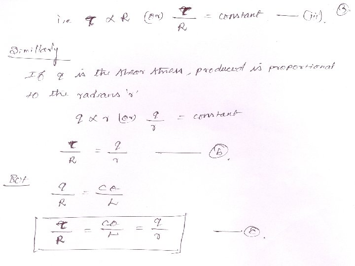
TORSION OF SHAFT A shaft is said to be in torsion, when equal and opposite torque are applied at the two ends of the shaft. Due to the application of the torque at the two ends, the shaft is subjected to a twisting moment. This causes the shear stress and shear strain in the material of the shaft. ASSUMPTION IN THEORY OF PURE TORSION The material of the shaft is homogeneous, perfectly elastic & obeys hookes law. Twist is uniform along the length of the shaft. The stress doest not exceed the limit of proportionality. Cross section of the shaft , which are plane before twist remain plane after twist. Strain & deformation are small.

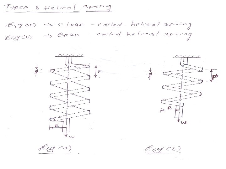
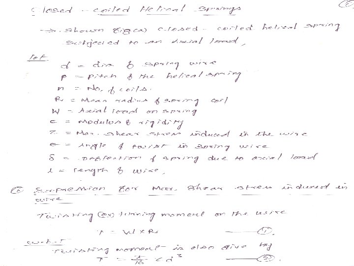
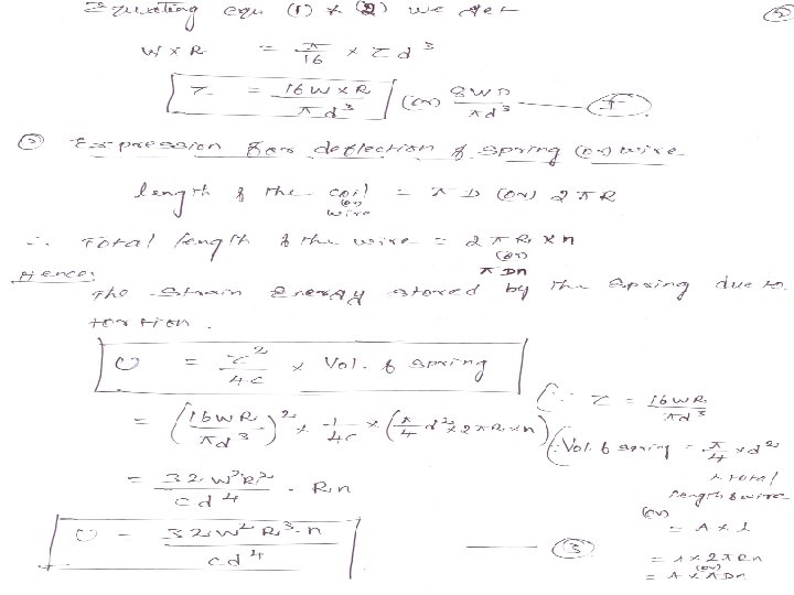
SPRING A spring is a device which is used to absorb energy by taking very large change in its from without permanent deformation and then release the same when it is required. For example, a carrying spring or leaf spring in an automobile which absorb road shock by continuously absorbing energy due to shock by their deformation and then dissipating the same by vibrating. TYPES OF SPRING 1. Helical Spring 2. Laminated or Leaf spring HELICAL SPRING A torsion spring is subjected to a twisting moment & the resilience is mainly due to torsion. The helical spring subjected to axial pull fall under this above category. Its are formed by winding a wire around a cylindrical mandrill in the form of helix. Its are the two types. i) Closed – Coiled helical spring ii) Open – Coiled helical spring.

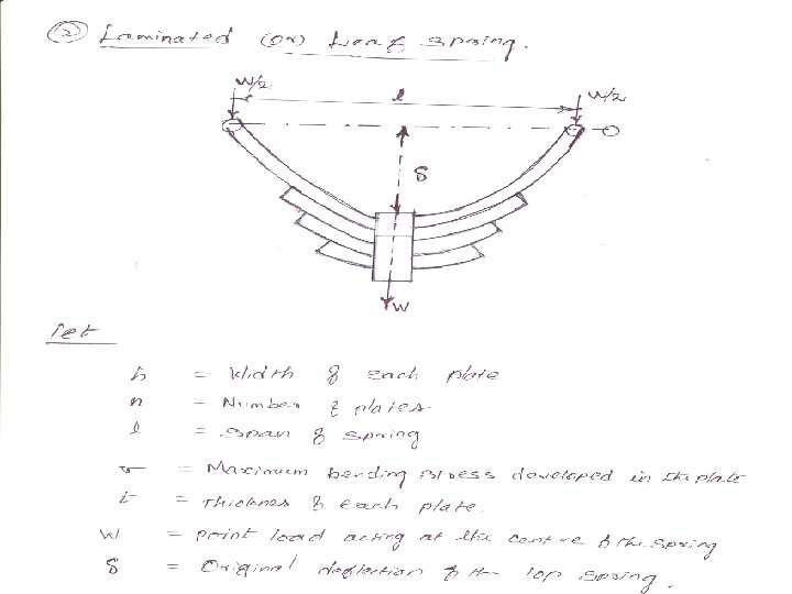
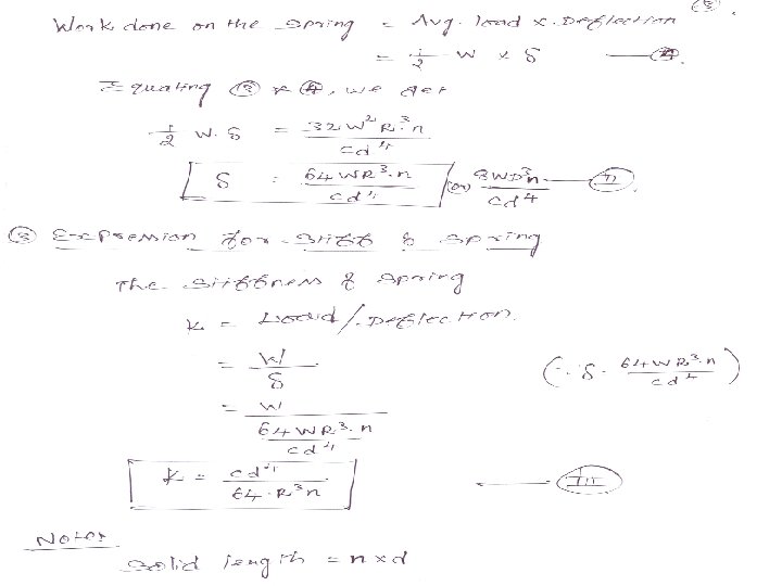
LAMINATED OR LEAF SPRING A leaf spring are used to absorb shock in railway wagons, coaches & road vehicle (cares, lorries etc. , ) Fig © shows a leaf spring consist of a number of parallel strips of a metal having different length & same width, placed one over the other. STIFFENESS(K) The stiffness of a spring is defined as the load required to produce unit deflection. i. e. , W/
- Slides: 53