
DEEP SEA ELECTRONICS PLC Highfield House Hunmanby Industrial
DEEP SEA ELECTRONICS PLC Highfield House, Hunmanby Industrial Estate, Hunmanby, North Yorkshire YO 14 0 PH England TELEPHONE +44 (0) 1723 890099 FASCIMILE +44 (0) 1723 890099 EMAIL sales@deepseaplc. com DSEGENCOMM PROTOCOL DSE SERIAL PORT (RS 232/RS 485) AND ETHERNET CONTROLLERS www. deepseaplc. com
www. deepseaplc. com GENCOMM DESCRIPTION • Common protocol (designed by DSE) for GENerator COMMunication, used by DSE controllers since mid 1990’s. Covered by GENCOMM. doc • Protocol expanded for DSE 7000 and DSE 8000 series controllers. Additional functions covered by addendum documents. These controllers also support functions covered in GENCOMM. doc • Protocol documents are available upon request from support@deepseaplc. com and by specifying the serial number of your controller.
www. deepseaplc. com GENCOMM DESCRIPTION Modbus is a master – slave protocol. The master system queries data from the slave. The DSE controller is the slave device that responds to the master’s query. A query can be requesting information such as generator volts or can be a request for the controller to do something such as starting the generator. An invalid response may indicate that the module is too busy to respond or that the address requested is not supported by the controller. A valid response will either be the requested information, confirmation that a task has taken place or may be a sentinel value indicating some form of measurement error such as a sensor fault, or an out of range value.
www. deepseaplc. com GENCOMM DESCRIPTION To use GENCOMM you will need to be familiar with the following principles, in addition to these items being supported by your modbus master system : Modbus protocol Half duplex, two wire twisted pair transmission lines Hexadecimal and decimal conversion Binary conversion and bit analysis Signed and unsigned numbering 16 bit and 32 bit numbering
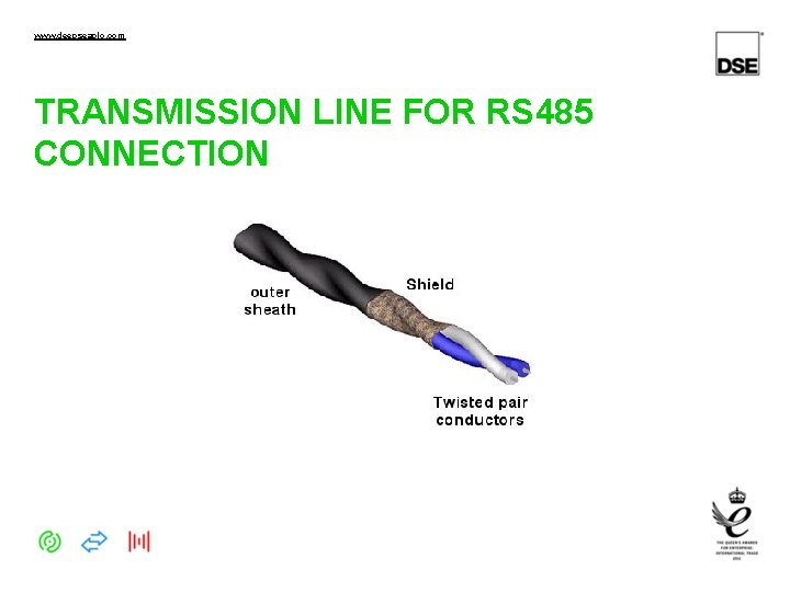
www. deepseaplc. com TRANSMISSION LINE FOR RS 485 CONNECTION
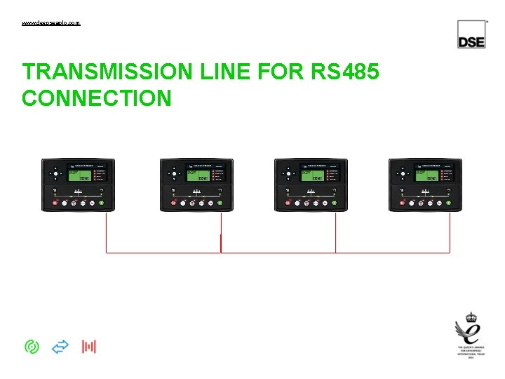
www. deepseaplc. com TRANSMISSION LINE FOR RS 485 CONNECTION
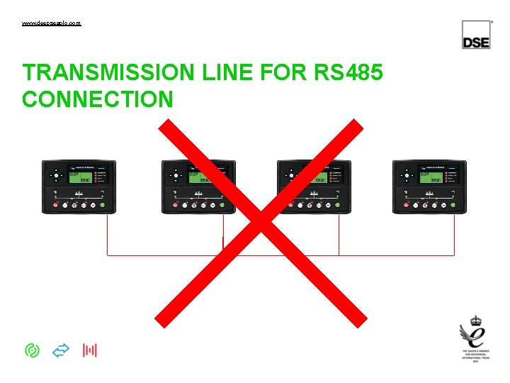
www. deepseaplc. com TRANSMISSION LINE FOR RS 485 CONNECTION
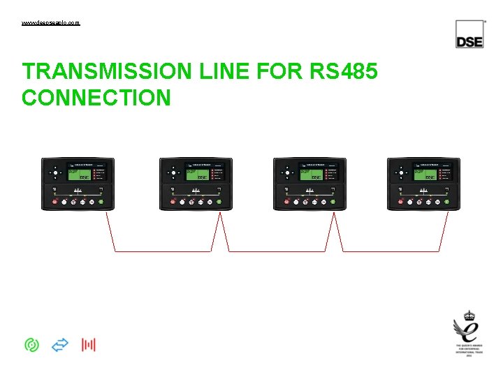
www. deepseaplc. com TRANSMISSION LINE FOR RS 485 CONNECTION
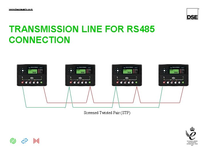
www. deepseaplc. com TRANSMISSION LINE FOR RS 485 CONNECTION Screened Twisted Pair (STP)
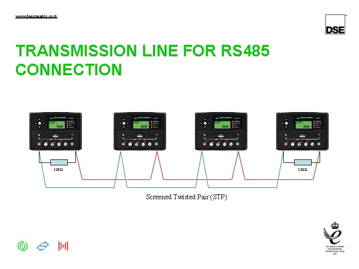
www. deepseaplc. com TRANSMISSION LINE FOR RS 485 CONNECTION 120Ω Screened Twisted Pair (STP)
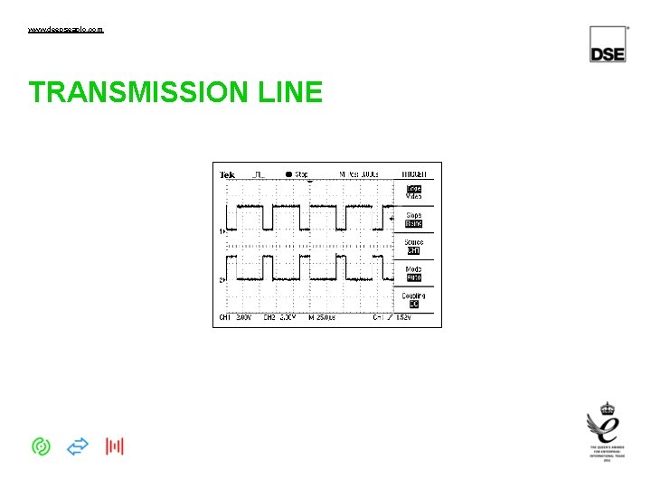
www. deepseaplc. com TRANSMISSION LINE
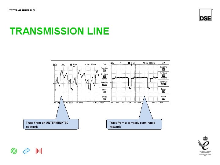
www. deepseaplc. com TRANSMISSION LINE Trace from an UNTERMINATED network Trace from a correctly terminated network
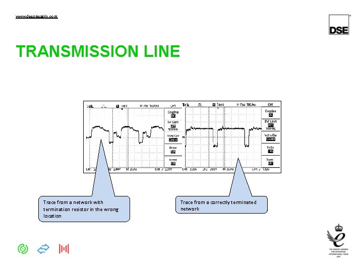
www. deepseaplc. com TRANSMISSION LINE Trace from a network with termination resistor in the wrong location Trace from a correctly terminated network
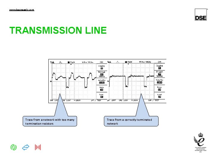
www. deepseaplc. com TRANSMISSION LINE Trace from a network with too many termination resistors Trace from a correctly terminated network
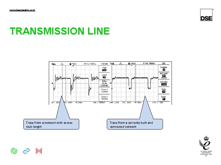
www. deepseaplc. com TRANSMISSION LINE Trace from a network with excess stub length Trace from a correctly built and connected network
www. deepseaplc. com DECIMAL, BINARY AND HEX Using modbus requires the use of no less than three number bases. Base 2 (Binary), Base 10 (Decimal) and Base 16 (Hexadecimal) 01 123456789 ABCDEF
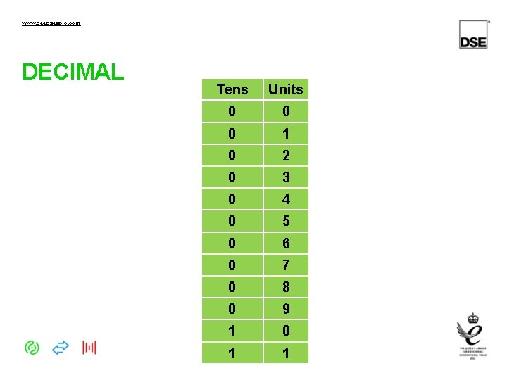
www. deepseaplc. com DECIMAL Tens Units 0 0 0 1 0 2 0 3 0 4 0 5 0 6 0 7 0 8 0 9 1 0 1 1
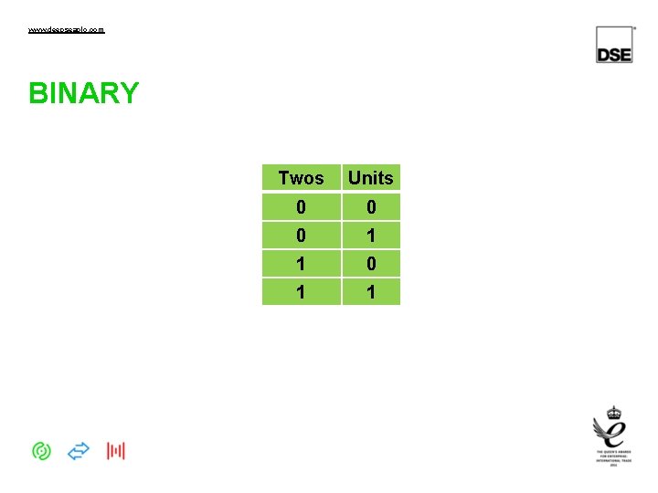
www. deepseaplc. com BINARY Twos Units 0 0 0 1 1
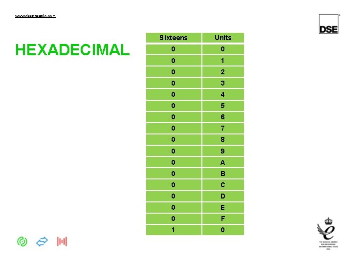
www. deepseaplc. com HEXADECIMAL Sixteens Units 0 0 0 1 0 2 0 3 0 4 0 5 0 6 0 7 0 8 0 9 0 A 0 B 0 C 0 D 0 E 0 F 1 0
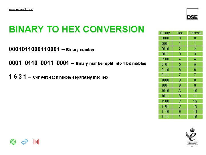
www. deepseaplc. com BINARY TO HEX CONVERSION 00010110001 – Binary number 0001 0110 0011 0001 – Binary number split into 4 bit nibbles 1 6 3 1 – Convert each nibble separately into hex Binary Hex Decimal 0000 0 0 0001 1 1 0010 2 2 0011 3 3 0100 4 4 0101 5 5 0110 6 6 0111 7 7 1000 8 8 1001 9 9 1010 A 10 1011 B 11 1100 C 12 1101 D 13 1110 E 14 1111 F 15
www. deepseaplc. com BUILDING A MODBUS QUERY DO NOT attempt to write your own modbus protocol driver. It is a standard protocol, used widely in the controls industry. Libraries exist for many PC languages and modbus master devices.
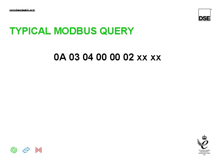
www. deepseaplc. com TYPICAL MODBUS QUERY 0 A 03 04 00 00 02 xx xx
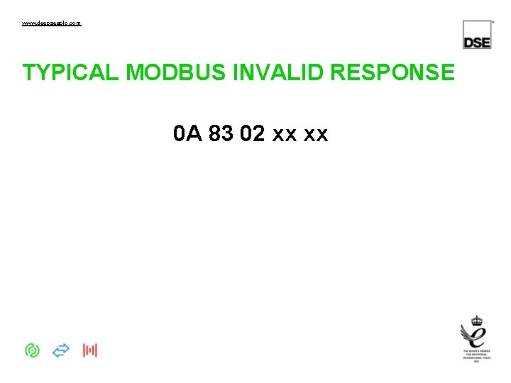
www. deepseaplc. com TYPICAL MODBUS INVALID RESPONSE 0 A 83 02 xx xx
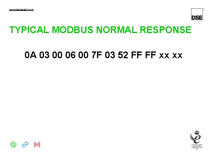
www. deepseaplc. com TYPICAL MODBUS NORMAL RESPONSE 0 A 03 00 06 00 7 F 03 52 FF FF xx xx
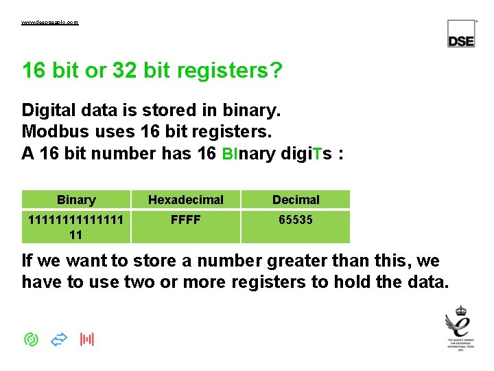
www. deepseaplc. com 16 bit or 32 bit registers? Digital data is stored in binary. Modbus uses 16 bit registers. A 16 bit number has 16 BInary digi. Ts : Binary Hexadecimal Decimal 1111111 11 FFFF 65535 If we want to store a number greater than this, we have to use two or more registers to hold the data.
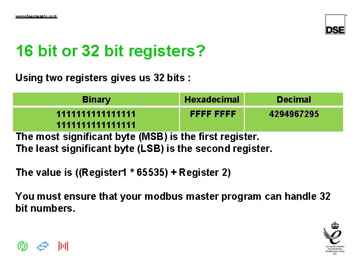
www. deepseaplc. com 16 bit or 32 bit registers? Using two registers gives us 32 bits : Binary Hexadecimal Decimal 1111111111111111 FFFF 4294967295 The most significant byte (MSB) is the first register. The least significant byte (LSB) is the second register. The value is ((Register 1 * 65535) + Register 2) You must ensure that your modbus master program can handle 32 bit numbers.
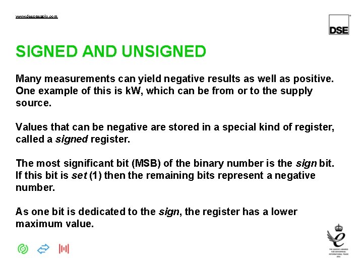
www. deepseaplc. com SIGNED AND UNSIGNED Many measurements can yield negative results as well as positive. One example of this is k. W, which can be from or to the supply source. Values that can be negative are stored in a special kind of register, called a signed register. The most significant bit (MSB) of the binary number is the sign bit. If this bit is set (1) then the remaining bits represent a negative number. As one bit is dedicated to the sign, the register has a lower maximum value.
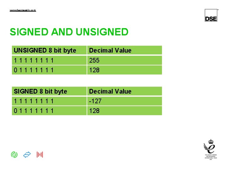
www. deepseaplc. com SIGNED AND UNSIGNED 8 bit byte Decimal Value 1111 255 01111111 128 SIGNED 8 bit byte Decimal Value 1111 -127 01111111 128
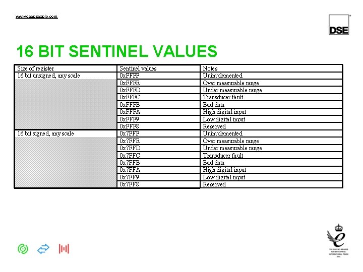
www. deepseaplc. com 16 BIT SENTINEL VALUES Size of register 16 bit unsigned, any scale 16 bit signed, any scale Sentinel values 0 x. FFFF 0 x. FFFE 0 x. FFFD 0 x. FFFC 0 x. FFFB 0 x. FFFA 0 x. FFF 9 0 x. FFF 8 0 x 7 FFF 0 x 7 FFE 0 x 7 FFD 0 x 7 FFC 0 x 7 FFB 0 x 7 FFA 0 x 7 FF 9 0 x 7 FF 8 Notes Unimplemented Over measurable range Under measurable range Transducer fault Bad data High digital input Low digital input Reserved
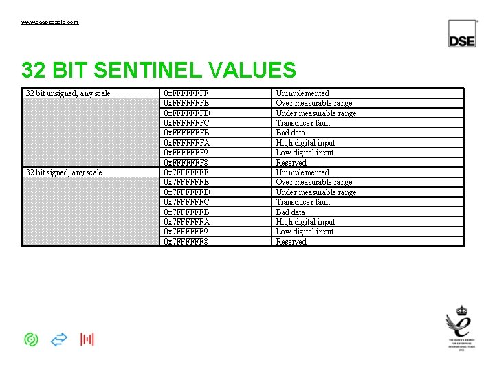
www. deepseaplc. com 32 BIT SENTINEL VALUES 32 bit unsigned, any scale 32 bit signed, any scale 0 x. FFFFFFFE 0 x. FFFFFFFD 0 x. FFFFFFFC 0 x. FFFFFFFB 0 x. FFFFFFFA 0 x. FFFFFFF 9 0 x. FFFFFFF 8 0 x 7 FFFFFFF 0 x 7 FFFFFFE 0 x 7 FFFFFFD 0 x 7 FFFFFFC 0 x 7 FFFFFFB 0 x 7 FFFFFFA 0 x 7 FFFFFF 9 0 x 7 FFFFFF 8 Unimplemented Over measurable range Under measurable range Transducer fault Bad data High digital input Low digital input Reserved
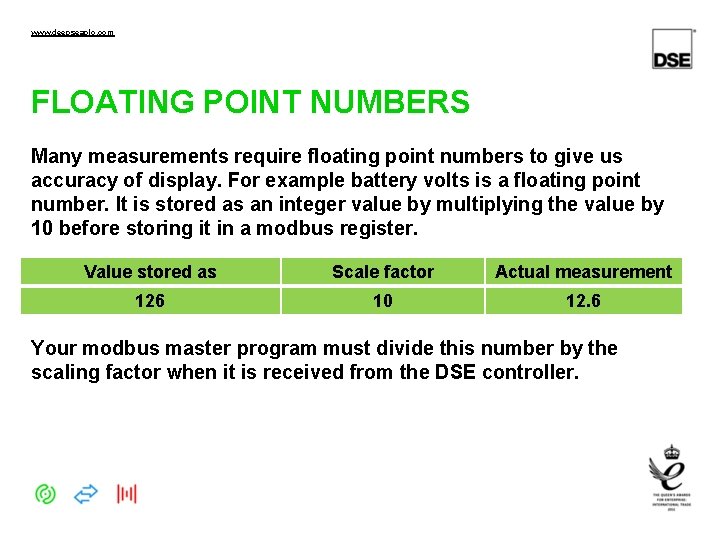
www. deepseaplc. com FLOATING POINT NUMBERS Many measurements require floating point numbers to give us accuracy of display. For example battery volts is a floating point number. It is stored as an integer value by multiplying the value by 10 before storing it in a modbus register. Value stored as Scale factor Actual measurement 126 10 12. 6 Your modbus master program must divide this number by the scaling factor when it is received from the DSE controller.
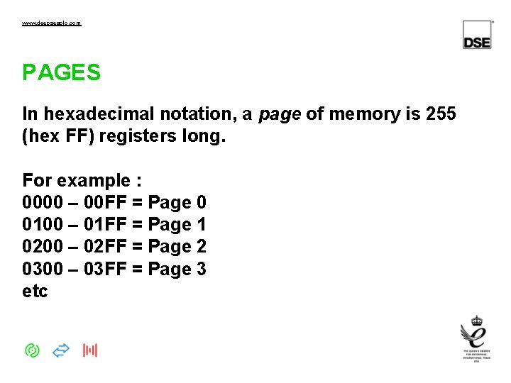
www. deepseaplc. com PAGES In hexadecimal notation, a page of memory is 255 (hex FF) registers long. For example : 0000 – 00 FF = Page 0 0100 – 01 FF = Page 1 0200 – 02 FF = Page 2 0300 – 03 FF = Page 3 etc
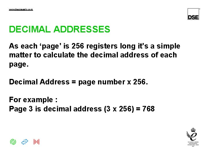
www. deepseaplc. com DECIMAL ADDRESSES As each ‘page’ is 256 registers long it’s a simple matter to calculate the decimal address of each page. Decimal Address = page number x 256. For example : Page 3 is decimal address (3 x 256) = 768
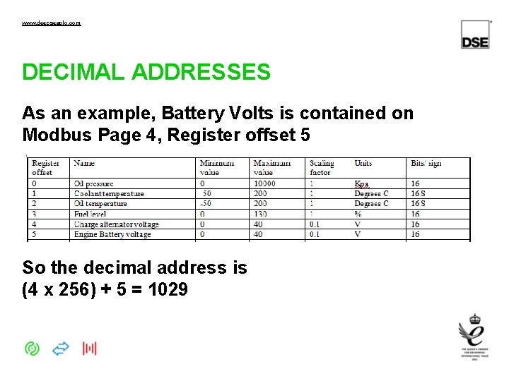
www. deepseaplc. com DECIMAL ADDRESSES As an example, Battery Volts is contained on Modbus Page 4, Register offset 5 So the decimal address is (4 x 256) + 5 = 1029
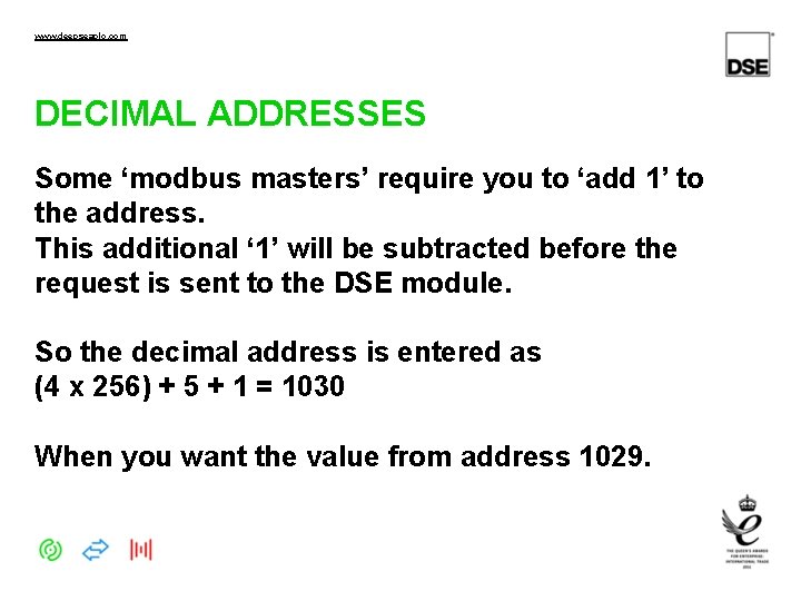
www. deepseaplc. com DECIMAL ADDRESSES Some ‘modbus masters’ require you to ‘add 1’ to the address. This additional ‘ 1’ will be subtracted before the request is sent to the DSE module. So the decimal address is entered as (4 x 256) + 5 + 1 = 1030 When you want the value from address 1029.
www. deepseaplc. com DECIMAL ADDRESSES Some ‘modbus masters’ use different numbering schemes, such as requiring you to ‘add 40, 000’ to the address. This type of addressing is not covered by this training course.
www. deepseaplc. com GENCOMM ADDRESSES The DSE module has a lot of information accessible through Gencomm. It uses the full modbus address range of 0000 – FFFF (hexadecimal) 0 – 65535 (decimal) So you need to ensure your modbus master supports full ‘ 32 bit addressing’ to cover the range of registers in the DSE module.
www. deepseaplc. com FURTHER TRAINING Further training on DSE Gencomm can be obtained from the following presentations and documents Documents 056 -045 PLC as Load Demand Controller 056 -051 Gencomm Control Keys 056 -080 Modbus Training Presentations 056 -076 Gencomm Alarms 056 -079 Gencomm Status
- Slides: 38