DC motor and PWM Sepehr Naimi www Nicer


- Slides: 32

DC motor and PWM Sepehr Naimi www. Nicer. Land. com

Topics n n Making Robots with Motors DC motor n n n Unidirectional control Bidirectional control PWM n n generating waves with different duty cycles Controlling motor speed using PWM 2

Some robots with 2 DC motors 3

DC motor 4

Unidirectional control +12 V Analog Ground M VCC MCU GND TIP 120 Analog Power +3. 3 V Digital Ground 5

Bidirectional control 6

Bidirectional (clock wise) 7

Bidirectional (counter clockwise) 8

Bidirectional 9

L 298 10

Using L 298 N 11

L 298 module 12

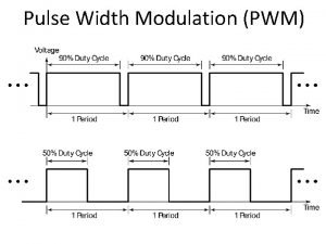
PWM and Duty Cycle 13

PWM in STM 32 F 10 x 14

CNT, ARR, and PSC 15

Counting Direction CMS 00 00 01 10 11 DIR 0 1 X X X Counting mode Counting up Counting down Count up and down Counting event (interrupt flag set) When the counter reaches ARR When the counter reaches 0 and ARR 16

Timer channels 17

CCMR 1 and CCMR 2 OCn. M: Output Compare n Mode OCn. M Mode n OCn. PE: Output Compare n Preload Enable. n 000 Frozen Compare match has no effect on the GPIO pin TIMx_CCRn notoutput buffered, 001 n 0: Active on match is The activates when CNT is equal to CCRn. 010 n 1: Inactive match The output becomes inactive when CNT=CCRn. It is on buffered. 011 Toggle on match The output toggles when CNT is equal to CCRn. n CCn. S: Compare/Capture n Selection 100 Force inactive It forces the GPIO pin to inactive level. output 101 n 00: Force activecompare, It forces the GPIO pin to active level. 110 n otherwise: PWM 1 input capture The output is active when CNT is less than CCRn. 111 PWM 2 (inverted) The output is inactive when CNT is less than CCRn. 18

PWM in Up-Counting Mode 19

PWM 1 20

Duty cycle & Frequency n ARR = 8, CCRn= 5, OCn. M = 110 (PWM 1) 21

Example n Find the frequency (F) and pulse width (DC, duty cycle) of a PWM if TIMx_ARR=999 and TIMx_CCRn=250. Assume OCn. M = 110 (PWM 1), no prescaler, and TIMx clock frequency of 72 MHz. Solution: Frequency=72 M/(999+1)=72 KHz=72000 Hz. The Duty Cycle is [TIMx_CCR/(TIMx_ARR +1)] × 100 = (250/1000) × 100 = 25%. 22

Shadow registers and Preloading ARPE: Auto-reload Preload Enable 1: ARR is buffered 23

TIMx_EGR (Event Generating Register) n If the UG (update generation) bit of TIMx_EGR is set, an update signal is generated and then hardware clears the UG bit automatically. 24

Example: generating a 100 Hz wave with D. C. of 30% #include <stm 32 f 10 x. h> int main( ) { RCC->APB 2 ENR |= 0 x. FC; RCC->APB 1 ENR |= (1<<0); GPIOA->CRL = 0 x 4444444 B; /* enable GPIO clocks */ /* enable TIM 2 clock */ /* PA 0: alternate func. output */ TIM 2 ->CCER = 0 x 1 << 0; /* CC 1 P = 0, CC 1 E = 1 */ TIM 2 ->CCMR 1 = 0 x 0068; /* OC 1 M=PWM 1, OC 1 PE=1 */ TIM 2 ->CR 1 = 0 x 80; /* Auto reload preload enable */ TIM 2 ->PSC = 720 -1; TIM 2 ->ARR = 1000 -1; TIM 2 ->CCR 1 = 300; /* prescaler = 720 */ /* ARR = 999 */ /* duty cycle = (300/1000)*100 */ TIM 2 ->EGR = 1; /* UG = 1 (generate update) */ TIM 2 ->CR 1 |= 0 x 01; /* timer enable (CEN = 1) */ while(1) { } } 25

PWM in Down-Counting Mode 26

Up-down Counting (Center-aligned) 27

Duty Cycle and frequency n 28

Example: Generating a wave with frequency of 1 k. Hz and duty cycle of 70% #include <stm 32 f 10 x. h> int main( ) { RCC->APB 2 ENR |= 0 x. FC; /* enable GPIO clocks */ RCC->APB 1 ENR |= (1<<1); /* enable TIM 3 clock */ GPIOA->CRL = 0 x. B 4444444; /* PA 7: alternate func. output */ TIM 3 ->CCER = 0 x 1 << 4; /* CC 2 P = 0, CC 2 E = 1 */ TIM 3 ->CCMR 1 = 0 x 6800; /* OC 2 M=PWM 1, OC 2 PE=1 */ TIM 3 ->CR 1 = 0 x. A 0; // Auto reload preload enable, up down counting mode TIM 3 ->PSC = 0; /* prescaler = 1 */ TIM 3 ->ARR = 32000; /* ARR = 32000 */ TIM 3 ->CCR 2 = 25200; /* duty cycle = (25200/32000)*100 */ TIM 3 ->EGR = 1; /* UG = 1 (generate update) */ TIM 3 ->CR 1 |= 0 x 01; /* timer enable (CEN = 1) */ while(1) { } } 29

Edge-aligned vs. Center-aligned 30

Unidirectional Speed Control +12 V VCC GND MCU AVR OC 0 A TIMx_CHn Analog Ground M TIP 120 Analog Power +3. 3 V Digital Ground 31

Bidirectional Speed Control 32
 Memory map
 Nicer globe
 Nicer land
 Sepehr sani
 Sarah naimi
 Adjective comparative superlative nice
 Nicerland
 Nicer land
 Trackinger1
 Nicer
Nicer Nicerland
 Nicer land
 Motor neuron
 Svm pwm
 Pwm sinyali
 Pwm with 555 timer
 Space vector pwm
 Pwm advantages
 176x5
176x5 Pwm in embedded system
 Pulsos: pam, ppm, pwm, pcm, ask, fsk, psk, qam
 Center aligned pwm
 Contoh aplikasi pwm
 Arduino pwm örnek
 Arduino multi task
 Avr block diagram
 Pwm block diagram
 Pwm arduino frequenza
 Pulse width
 Semnal pwm definitie
 Pwm arduino ø´ø±ø
 Ccp 1
Ccp 1 556 pwm circuit


