DC Generators Construction Working Principle Classification of windings


- Slides: 15
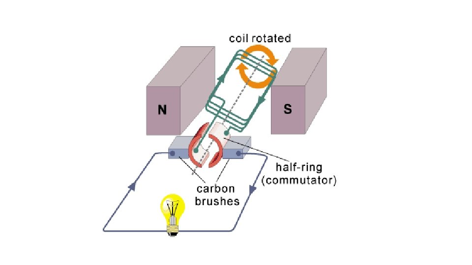
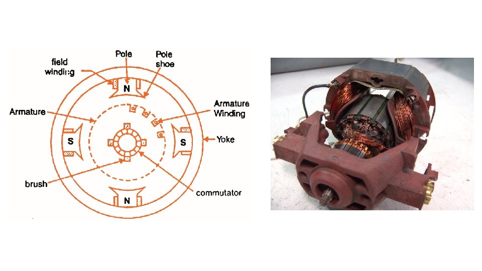
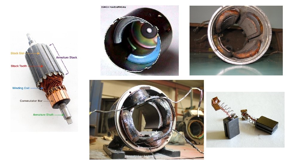
DC Generators Construction, Working Principle
Classification of windings: Closed type and open type winding Closed type windings: In this type of winding there is a closed path around the armature or stator. Starting from any point, the winding path can be followed through all the turns and starting point can be reached. Such windings are used in DC machines. Open windings: There is no closed path in the windings. Such windings are used in AC machines. DC Windings: Two types of windings (a) Lap winding (b) Wave winding These two types of windings differ in two ways (i) number of circuits between positive and negative brushes (ii) the manner in which the coil ends are connected. However the coils of both lap and wave windings are identically formed.
Lap winding
14 Slot, 4 pole, 2 coil sides per slot 23 25 27 2 4 6 3 1 2 25 27 7 5 4 6 9 8 10 11 12 13 14 15 16 17 18 19 20 21 22 23 24 25 26 27 28
Draw the winding diagram of a D C Machine with 4 poles, 14 slots, progressive, double winding. Show the position of brushes and direction of induced emf. layer lap Soln: back pitch yb = 2 c/p ± k For lap winding both Yb and Yf must be odd and differ by 2 Satisfying the above condition Yb = 7 and Yf = 5 (Winding diagram and ring diagrams are shown below)
Lap winding: -Number of parallel paths=No. of poles No. of brushes= No. of poles
Ring diagram
Wave winding: -Number of parallel paths=2 No. of brushes=2
WINDING DIAGRAM - WAVE
WINDING DIAGRAM – WAVE…
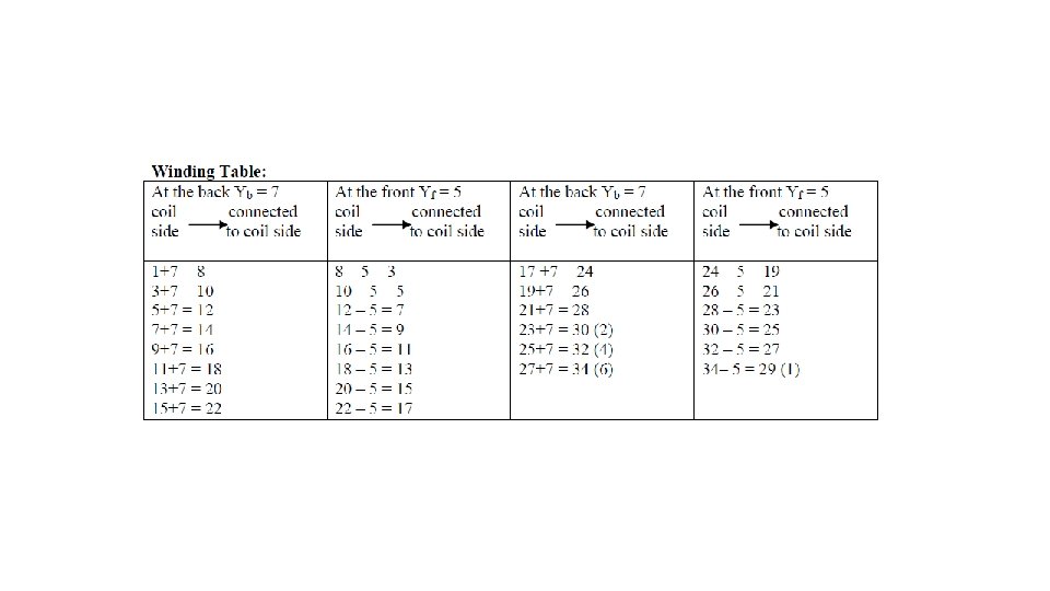
Develop a wave winding diagram for a DC machine having 34 armature conductors accommodated in 17 slots and 4 poles. Draw the sequence diagram indicate the position of the brushes, show the direction of induced emf. Soln: Number of poles = 4, slots = 17 No of conductors = 34 For wave winding (Yb + Yf)/2 = (Z ± 2)/p (Yb + Yf )/ 2 = 18 Taking Yb = Yf Yb = 9 and Yf = 9 (If fraction take nearest lower integer)