DC CIRCUITS CHAPTER 3 Methods of Circuit Analysis


- Slides: 147

DC CIRCUITS: CHAPTER 3

Methods of Circuit Analysis and Circuit Theorems: ¡ ¡ ¡ ¡ Nodal Analysis (Node-Voltage Method) Mesh Analysis (Mesh-Current Method) Superposition Theorem Source Transformation Thevenin’s Theorem Norton’s Theorem Maximum Power Transfer

Introduction ¡ ¡ ¡ Direct methods are not suitable to solve complex and large circuits or as we demand many unknowns. To aid the analysis of complex circuit structures-need to develop more powerful techniques from the basic laws by systematic approaches: Nodal Analysis and Mesh Analysis. These two techniques can be used to solve almost any kind of circuit analysis problems by means of a set of simultaneous equations.

Introduction (Continued…) Four ways of solving simultaneous equations: 1. Cramer’s rule 2. Calculator (real numbers only) 3. Normal substitution and elimination (not more than two equations) 4. Computer program packages: matcad, maple, mathematica etc. ¡

Introduction (Continued…) ¡ ¡ Circuit analysis problems in this course will be limited to three linear simultaneous equations for conventional hand solutions. Circuit theorems merely developed to simplify circuit analysis applicable to linear circuits such as Thevenin’s and Norton’s theorems, superposition theorem, source transformation and maximum power transfer.

Introduction (Continued…) ¡ ¡ Circuit theorems are not analysis techniques, rather they add up to the list of simplifying/reduction techniques such as the series-parallel reductions and -Y transformations. Although many computer aids facilitate us as effective mathematics tools to solve engineering problems they cannot replace the compulsory needs to study the circuit theories govern circuit behavior in performing both circuit analysis and design.

Circuit Analysis Method NODAL ANALYSIS

Concept Developed based on the systematic approach of Kirchhoff’s current law (KCL) to find all circuit variables without having to sacrifice any of the elements. ¡ General procedure which is making use of node voltages in circuit analysis as key solutions. ¡

Importance terms Node Voltage: Potential difference between a marked node and the selected reference node. ¡ Element Voltage: Potential difference across any element or branch in the circuit. ¡ When Node Voltage = Element Voltage? ¡

Why use Node Voltage? Further reduce the number of equations to be solved simultaneously. ¡ No of independent equations = No of the marked nodes exclusive of the reference node. ¡ Element voltages and currents can be obtained in few steps using the solved node voltages. ¡

Assumptions KCL is performed with current going out from a node as positive (+ve) while current entering a node as negative (-ve). in – negative (subtract) out – positive (add) ¡ All unknown currents assumed to be leaving a particular node. ¡

Nodal Analysis Procedures: 1. 2. 3. Mark all essential nodes and assign proper voltage designations except for the appointed reference node. Apply KCL to each nonreference nodes. Use Ohm’s law to formulate the equation in terms of node voltages. Assume all unknown currents are directing out of the nodes. Solve the resulting simultaneous equations to obtain the unknown node voltages.

Applying Nodal Analysis on Simple Circuit Example 1 (3 unknowns)

Solution Step 1: V 1 ¡ Mark all essential nodes ¡ Assign unknown node voltages ¡ Indicate the reference node. V 2 V 3

Solution (continued…) ¡ Step 2: Perform KCL at each marked nonreference nodes using Ohm’s law to formulate the equations in terms of the node voltages.

Solution (continued…) ¡ KCL V 1: (1) or ¡ KCL V 2: (2) ¡ KCL V 3: (3)

Solution (continued…) ¡ Step 3: Solve the resulting simultaneous equations from step 2 above.

Solution (continued…) ¡ KCL V 1: Simplify to ¡ (1) KCL V 2: Simplify to ¡ V 1 - V 2 = 50 -2 V 1 + 11 V 2 - 4 V 3 = 0 (2) KCL V 3: Simplify to -2 V 2 + 7 V 3 = -30 (3)

Solution (continued…) ¡ Cramer’s rule: Put the equations in matrix forms. Col-1 Col-2 Col-3 = Left Col-1: Col-2: Col-3: ¡ ¡ ¡ Matrix: coefficients of V 1 i. e. a 1, a 2 and a 3 coefficients of V 2 i. e. b 1, b 2 and b 3 coefficients of V 3 i. e. c 1, c 2 and c 3 Middle Matrix: Right Matrix: Unknown variables i. e. V 1, V 2 and V 3 Constants i. e. d 1, d 2 and d 3

Solution (continued…) ¡ ¡ For third-order determinants, we use shorthand methods of expansion solution. Shorthand method consists of repeating the first two columns of the determinant to the right of the determinant and then summing the products along the specific diagonals as shown below.

Solution (continued…) ¡ Use determinants to solve for each variable: 1 -2 0 -1 11 -2

Solution (continued…) ¡ Determinant 1 when coefficients for V 1 is replaced by the constants. 50 0 -30 -1 11 -2

Solution (continued…) ¡ Determinant 2 when coefficients for V 2 is replaced by the constants. 1 50 -2 0 0 -30

Solution (continued…) ¡ Determinant 3 when coefficients for V 3 is replaced by the constants. 1 -2 0 -1 11 -2

Solution (continued…) V 1 = 1/ = 3330/55= 60. 55 V ¡ V 2 = 2/ = 580/55 =10. 55 V ¡ V 3 = 3/ = -70/55 =-1. 27 V ¡ ¡ You should verify your answers using calculator for three unknowns.

Solution (continued…) ¡ Knowing all the node voltages, we can obtain the element voltages, element currents and even power dissipated by the passive elements such as: VR 1= V 1 – V 2 IR 1 = (V 1 – V 2)/R 1 PR 1 = IR 12 R 1 = VR 12/R 1 VR 2= V 2 – V 3 IR 1 = (V 2– V 3)/R 2 PR 2 = IR 22 R 2 = VR 22/R 2 **VR 3= V 2 IR 1 = V 2/R 3 PR 3 = IR 32 R 3 = VR 32/R 3 **VR 4= V 3 IR 4 = V 32/R 4 PR 4 = IR 42 R 3 = VR 42/R 4 **In these two cases, the element voltages identical to node voltages because one of its terminals is at reference node.

Can you find the power dissipated by the 10 k resistor? ¡ ¡ Need to find the element voltage of 10 -k resistor because power calculation formula uses element voltage. P 10 k = (V 1 – V 2)2/10 k = (60. 55 – 10. 55)2/10 k = 502/10 k = 0. 25 W

Applying Nodal Analysis on Simple Circuit Example 2 (2 unknowns) Q: Find the power dissipated in the 20 - resistor?

Solution Step 1: ¡ Mark all essential nodes ¡ Assign unknown node voltages ¡ Indicate the reference node.

Solution (Continued…) ¡ Step 2: Perform KCL at each KCL V 1: marked nonreference Hence nodes using Ohm’s law to formulate the KCL V 2: equations in terms of node voltages. Hence (1) (2)

Solution (Continued…) ¡ Step 3: Solve the resulting simultaneous equations which have been simplified in step 2 above using Cramer’s rule.

Solution (Continued…) Hence, V 1 = 1/ = 6. 8/17 = 0. 4 V V 2 = 2/ = 1. 7 /17 = 0. 1 V P 20 = V 22/20 = 0. 12(20) = 0. 2 W #

Applying Nodal Analysis on Circuit with Voltage Sources Three different effects depending on placement of voltage source in the circuit. ¡ Does the presence of a voltage source complicate or simplify the analysis? ¡

Case 1: Voltage source between two nonreference essential nodes. Supernode Equation:

Case 2: Voltage source between a reference essential node and a nonreference essential node. Known node voltage:

Case 3: Voltage source between an essential node and a non-essential node. Node voltage at non-essential node:

Example 3 (Supernode or Known node voltage) ¡ Q: Find the power of the 10 -V voltage source? Is it supplying energy to the circuit or absorbing energy from the circuit? Show your work according to the nodal analysis procedure.

Solution 1 (Supernode) ¡ Step 1: Mark essential nodes and assign unknown node voltages and indicate the reference node. Checklist: 3 essential nodes – 1 ref node – 1 supernode = 1 KCL Eqn. + 1 Supernode Eqn.

Solution 1 (Continued…) ¡ Step 2: Perform KCL at each marked nonreference nodes using Ohm’s law to formulate the equations in terms of node voltages. KCL supernode V 1/V 2: Hence Supernode Equation: (1) (2)

Solution 1 (Continued…) Step 3: Solve the resulting simultaneous equations which have been simplified in step 2 above. ¡ Solving Eqn. (1) and (2) simultaneously yields, ¡ V 1 = 30. 91 V and V 2 = 20. 91 V ¡ (You can check this answer by calculator or Cramer’s rule). ¡

Solution 1 (Continued…) ¡ ¡ Finding current through the voltage source, KCL at V 1: Hence, P 10 -V = Vi= (10)(-0. 636) = -6. 36 W. (Delivering energy)

Solution 2 (Known node voltage) ¡ Step 1: Mark essential nodes and assign unknown node voltages and indicate the reference node. Checklist: 3 essential nodes – 1 ref node – 1 known node voltage = 1 KCL Eqn.

Solution 2 (Continued…) ¡ Step 2: Perform KCL at each marked nonreference nodes using Ohm’s law to formulate the equations in terms of node voltages. Immediately known node voltage at V 1: KCL V 2: (1)

Solution 2 (Continued…) ¡ Step 3: Solve the resulting simultaneous equations which have been simplified in step 2 above. Solving Eqn. (1) yields, Finding current through the voltage source, KCL at V 1:

Solution 2 (Continued…) Hence, ¡ P 10 -V = Vi= (10)(-0. 636) = -6. 36 W. (Delivering energy) ¡

Example 4 (One of the terminals not an essential node) ¡ Q: Find the current through the 10 -k resistor. Show your work according to the nodal analysis procedure.

Solution ¡ Step 1: Mark essential nodes and assign unknown node voltages and indicate the reference node. For voltage sources, indicate the node voltages at both ends with respect to the assigned unknown node voltages at the essential nodes Checklist: 4 essential nodes – 1 ref node = 3 KCL Eqns.

Solution (Continued…) ¡ Step 2: Perform KCL at each marked nonreference nodes using Ohm’s law to formulate the equations in terms of node voltages. KCL V 1: Hence (1) KCL V 2: Hence (2)

Solution (Continued…) KCL V 3: Hence (3)

Solution (Continued…) Step 3: Solve the resulting simultaneous equations which have been simplified in step 2 above. ¡ Solving Eqn. (1) till (3) simultaneously yields, V 1 = -5. 43 V, V 2 = -10. 17 V and V 3 = 12. 13 V (You can check this answer by calculator and Cramer’s rule). ¡

Solution (Continued…) Finding current through the 10 -k resistor, ¡ KCL at V 2: ¡

Applying Nodal Analysis on Circuit with Dependent Sources ¡ ¡ ¡ Circuits contain dependent sources either VCVS, CCVS, VCCS or CCCS. The presence of the dependent sources require ‘Constraint Equation’ (CE). CE describes the dependent term of the dependent sources in relation to the assigned unknown node voltages or known values at the essential nodes.

Example 5 (Circuit with dependent sources) ¡ Q: Use the node-voltage method to find both dependent terms i. O and Vx of the dependent sources of the circuit in Figure below.

Solution ¡ Step 1: Mark essential nodes and assign unknown node voltages and indicate the reference node. Checklist: 4 essential nodes – 1 ref node – 1 s/node – 1 known = 1 KCL Eqn. + 1 s/node Eqn. + 2 contraint Eqns.

Solution (Continued…) ¡ Step 2: Perform KCL at each marked nonreference nodes using Ohm’s law to formulate the equations in terms of node voltages. Known node voltage: KCL s/node V 2: Hence S/node equation: (1) (2)

Solution (Continued…) Constraint equations: (3) and Hence (4) Substituting Eqn. (3) into (2) yields (2’)

Solution (Continued…) ¡ ¡ Step 3: Solve the resulting simultaneous equations which have been simplified in step 2 above. Solving Eqn. (1), (2’) and (4) simultaneously yields, V 1 = -6. 51 V, V 2 = 1. 83 V and io = -0. 264 A ¡ (You can check this answer by calculator and Cramer’s rule).

Chapter 3, Problem 16. ¡ Determine voltages v 1 through v 3 in the circuit of Fig. 3. 64 using nodal analysis. (Ans: V 1=18. 86 V, v 2=6. 29 V, V 3=13 V) Figure 3. 64

Chapter 3, Problem 30. ¡ Using nodal analysis, find vo and io in the circuit of Fig. 3. 78. (Ans: Vo=-1. 344 k. V, io=-5. 6 A) Figure 3. 78

Chapter 3, Problem 31. ¡ Find the node voltages for the circuit in Fig. 3. 79. (Ans: V 1=4. 97 V, V 2=4. 85 V, V 3=-0. 1212 V) Figure 3. 79

Chapter 3, Problem 32. ¡ Obtain the node voltages v 1, v 2, and v 3 in the circuit of Fig. 3. 80. (Ans: V 1=2 V, V 2=12 V, V 3=-8 V) Figure 3. 80

Circuit Analysis Method MESH ANALYSIS

Concept Similar to nodal analysis. ¡ Developed based on the systematic approach of Kirchhoff’s voltage law (KVL) to find all circuit variables without having to sacrifice any of the elements. ¡ General procedure which is making use of mesh current in circuit analysis as key solutions. ¡

Importance terms Mesh Current: Assigned unknown current flows around the perimeter of the particular mesh/loop. ¡ Element Current: Actual current thru any element or branch in the circuit. ¡ When Mesh Current = Element Current? ¡

Assumptions ¡ KVL is performed in clockwise direction. Voltage rise – negative (subtract) Voltage drop– positive (add)

Mesh Analysis Procedures: 1. 2. 3. Label all independent meshes and assign proper unknown mesh currents in clockwise direction. Do the checklist. Formulate KVL/Supermesh/Constraint Equation. Solve the resulting simultaneous equations to obtain the unknown mesh current.

Applying Mesh Analysis on Simple Circuit PP 3. 5 (2 unknowns) Q: Find power dissipated in 12 -resistor and 3 -resistor using mesh analysis. ¡

Solution 1. Label all independent meshes and assign proper unknown mesh currents in clockwise direction. Checklist: 2 meshes = 2 KVL Eqns.

Solution (Continued…) 2. ¡ ¡ Formulate KVL/Supermesh/Constraint Eq. KVL I 1: 18 I 1 – 12 I 2 = 12 KVL I 2: -12 I 1 + 24 I 2 = -8 (1) (2)

3. ¡ ¡ Solve the Solution resulting (Continued…) simultaneous equations to obtain the unknown mesh current. I 1 = 1/ I 2 = 2/

Solution (Continued…) ¡ ¡ ¡ Using calculator/Cramer’s rule we obtain: I 1 = 0. 667 A and I 2 = 0 A P 12 = (I 1 -I 2)2(12) = 5. 33 W P 3 = I 22(3) = 0 W Notice that the branch (3 -resistor) forming the outer most boundary of the circuit will have mesh current = element current.

Circuit with current sources and dependent sources ¡ ¡ ¡ Two different effects depending on placement of voltage source in the circuit. Does the presence of a current source complicate or simplify the analysis? The presence of dependent source in the circuit need to impose constraint equation to describe the r/ship btw. dependent term of the dependent sources in relation to the mesh currents.

Case 1: Current source located at the outer most boundary ¡ ¡ ¡ Connecting mesh current immediately known. No need to apply KVL around that loop/mesh. Mesh Current = Element Current = Current Source Value Immediately known mesh current, I 3 = -Is

Case 2: Current source located at the boundary between 2 meshes ¡ ¡ ¡ Enclose the current source and combine the two meshes to form a SUPERMESH. KVL is performed around the supermesh – do not consider voltage across cur. source. Formulate s/mesh equation – express the r/ship btw mesh currents that form the s/mesh and cur. source that it encloses.

SUPERMESH ¡ KVL S/Mesh I 2/I 3: -12 + I 2 R 2 +I 3 R 3 + I 3 R 4=0 S/Mesh Eq: I 3 – I 2 = 3 m. A ¡

Practice Problem 3. 7 (S/Mesh) ¡ Use the mesh analysis to determine i 1, i 2 and i 3. Figure 3. 25

Solution ¡ Step 1: Checklist: 3 meshes – I s/m = 2 KVL Eqns. + 1 s/node Eq.

Solution (Continued…) Step 2: Formulate KVL/s. mesh equation. (1) ¡ KVL i 3: -2 i 1 – 4 i 2 + 8 i 3 = 0 ¡ KVL s/mesh i 1/i 2: 2 i 1 + 12 i 2 – 6 i 3 = 6 (2) ¡ S/Mesh Eq: i 1 – i 2 = 3 (3) ¡

Solution (Continued…) Step 3: Solve the simultaneous equations using Cramer rule or by calculator. ¡ We obtain, i 1 = 3. 474 A i 2 = 0. 4737 A i 3 = 1. 1053 A ¡

Example 6 ( Known current & dependent source) ¡ Find the voltage of the dependent source (CCCS).

Solution ¡ Step 1: Assign mesh currents in CW direction and perform checklist. Checklist: 2 meshes – I known = 1 KVL Eqn. + 1 CE

Solution (Continued…) ¡ Step 2: Formulate KVL/Constraint equations. ¡ Immediately known, I 1 = 5 ix ¡ KVL I 2: 21 I 2 = -8 ¡ CE: ix = I 2 (1) (2) (3)

Solution (Continued…) Step 3: Solve the simultaneous equations. ¡ Substitute (3) into (1) and solve (1) and (2) simultaneously, we obtain ¡ I 1 = -1. 9048 A I 2 = -0. 3810 A ¡

Solution (Continued…) ¡ To find voltage across the CCCS, perform KVL around loop I 1. KVL I 1: -V + 9 I 1 – 8 = 0 V = 9(-1. 9048) – 8 = 25. 1432 V

Chapter 3, Problem 55. ¡ In the circuit of Fig. 3. 97, solve for i 1, i 2, and i 3. (Ans: i 1=-1 A, i 2=0 A, i 3=2 A) Figure 3. 97

Circuit Theorem SUPERPOSITION

Advantages Use of superposition theorem: to find solution to circuits with multiple independent sources which are neither series nor parallel. ¡ Advantage: no need to solve simultaneous equations (tedious computation for complex cct) in order to find the circuit variables by simplification techniques. ¡

Concept ¡ Concept: each independent source is treated independently and the algebraic sum is found to determine a particular unknown quantity or circuit variable of the circuit under study.

Superposition Theorem ST states that: “ The current or voltage of any element in a bilateral circuit is equal to the algebraic sum of the currents or voltages produced independently by each source. ” ¡

Principle of Operation ¡ ¡ To consider the effect of each source independently requires that source to be removed and replaced without affecting the final results. To remove voltage source – s. c the terminals. To remove current source – o. c the terminals. Any dependent source treated as though they are passive element (must be left intact during the process).

Example 6 (P 3. 5) ¡ Find the voltage across the 12 resistor using superposition hence the power dissipated by this resistor.

Solution ¡ i) Consider 12 V/removed 8 V.

Solution (Continued…) ¡ ii) Replace 8 V/removed 12 V

Solution (Continued…) Hence, V = V’ + V’ = 6 V + 2 V = 8 V. ¡ P 12 = V 2/R = 82/12 = 5. 33 W ¡

Example 7 ¡ Find the current in the 23 resistor using the concept of superposistion. (Ans: 11. 23 A)

Exercise 1 ¡ Using superposition, find the voltage V in the circuit? (Ans: 40 V)

Circuit Theorem SOURCE TRANSFORMATON

What benefits from source transformation? Another tool to simplify circuit – the simpler the cct, the easier will be the solution. ¡ How to simplify? – rearrange the resistors/sources by S. Trans so that they end up with series/parallel connections. ¡

Principle of Operation The terminal v-i characteristics must retain before and after transformation as this concept is based on equivalence. ¡ S. Trans also applies to dependent sources. ¡ It does not affect the remaining part of the circuit. ¡

Definition ¡ A Source Transformation is the process of replacing a voltage source Vs in series with resistor Rs by a current source is in parallel with the same resistor Rs or vice versa.

Equivalent Circuits ¡ The connections of each case should be between the same terminals before and after transformation. In order for the circuits in the left and right sides to be equivalent:

Example 8 ¡ Use series of source transformations to find io in the circuit below.

Solution ¡ Transform 4 A and 5 into voltage source.

Solution (cntd…) ¡ ¡ Transform 10 A and 1 into voltage source. Transform 10 V and 40 into current source.

Solution (ctnd…) ¡ Transform 10 V and 10 into current source.

Solution (cntd…) ¡ ¡ ¡ Combine the current sources 2 A and 0. 25 A. Combine resistors 10 and 40. Solve for I using CDR.

Practice Problem 4. 6 ¡ Find io in the circuit of Figure 4. 19 using source transformation. (Ans: 1. 78 A)

Practice Problem 4. 7 ¡ Use S. Trans to find ix in the cct shown in Figure 4. 22. (Ans: 1. 176 A)

Exercise 2 ¡ Use STrans to find Vo. (Ans: -135 V)

Circuit Theorem THEVENIN’S THEOREM

Purpose ¡ ¡ ¡ Used when we are interested ONLY in the terminal behavior of the circuit particularly where a variable load is connected to. Provides a technique to replaced the fixed part of the circuit by a simple equivalent circuit. Avoid the re-do on the analysis of the entire circuit except for the changed load.

Thevenin’s Theorem ¡ States that “ A linear two-terminal circuit can be replaced by an equivalent circuit consisting of an open-circuit voltage source at the terminals, VTh in series with a resistor RTh where RTh is the input or equivalent resistance at the terminals when all independent source are turned off. ”

Replacing linear two-terminal (a-b) circuit by its Thevenin equivalent ¡ Original circuit

Replacing linear two-terminal (a-b) circuit by its Thevenin equivalent (Cntd) ¡ Thevenin equivalent circuit VTh - Thevenin voltage RTh - Thevenin resistance

Procedures to obtain VTh and RTh ¡ ¡ ¡ Step 1: Priliminary – Omitting load resistor RL (Not applicable if no load resistor) Step 2: Find RTh – setting all independent sources to zero. Find the resultant resistance between the marked terminals. Voltage source – s. c Current sorce – o. c Step 3: Find VTh – calculate VTh by returning all sources back to their original positions. Find the o. c voltage btw the marked terminals using the method which takes least effort.

Example 9 ¡ Find the Thevenin equivalent between terminal a-b. (Ans: VTh=32 V, RTh=8 )

Example 10 ¡ Find the Thevenin equivalent circuit at the terminal ab of the circuit below. (Ans: VTh=-4. 8 V, RTh=2. 4 )

Practice Problem 4. 8 ¡ Use the Thevenin’s theorem to find the equivalent circuit to the left of the terminals a-b in the circuit below. Then find i. (Ans: VTh=6 V, RTh=3 , i=1. 5 A)

Circuit Theorem NORTON’s THEOREM

Norton’s Theorem ¡ ¡ The purpose of its use is similar to the Thevenin’s theorem. States that “A linear two-terminal circuit can be replaced by an equivalent circuit consisting of a short circuit current source through the terminals, IN in parallel with a resistor RN where RN is the input or equivalent resistance at the terminals when all independent source are turned off. ”

Replacing linear two-terminal (a-b) circuit by its Norton equivalent (a) Original Circuit ¡ (b) Norton Equivalent Circuit ¡

Finding Norton current, IN

Procedures to obtain VTh and RTh ¡ ¡ ¡ Step 1: Priliminary – Omitting load resistor RL (Not applicable if no load resistor) Step 2: Find RTh – setting all independent sources to zero. Find the resultant resistance between the marked terminals. Voltage source – s. c Current sorce – o. c Step 3: Find VTh – calculate VTh by returning all sources back to their original positions. Find the o. c voltage btw the marked terminals using the method which takes least effort.

Procedures to obtain IN and RN ¡ ¡ ¡ Step 1: Priliminary – Omitting load resistor RL (Not applicable if no load resistor) Step 2: Find RN – setting all independent sources to zero. Find the resultant resistance between the marked terminals. Voltage source – s. c Current sorce – o. c Step 3: Find IN – calculate IN by returning all sources back to their original positions. Find the o. cs. c current btw the marked terminals using the method which takes least effort.

Example 10 ¡ Find the Norton Equivalent circuit with respect to the terminals a-b.

Practice Problem 4. 11 ¡ Find the Norton equivalent circuit in Figure below. (Ans: IN=4. 5 A, RN=3 )

Circuit Theorem THEVENIN & NORTON’s THEOREMS WITH DEPENDENT SOURCE

Procedures to obtain VTh/IN and RTh/RN ¡ ¡ ¡ Step 1: Priliminary – Omitting load resistor RL (Not applicable if no load resistor) Step 2: Find VTh = Vo. c or IN = Is. c using the method that takes the least effort. Step 3: Find RTh/RN Method 1: If circuit contains independent source. Rth = RN = Vo. c/Is. c = VTh/IN Method 2: If circuit contains independent source and without independent source.

Using Method 2 to find RTh/RN ¡ ¡ ¡ Turn off all independent sources but dependent sources left intact because they are controlled by circuit variables. Because of the presence of the dependent source, we excite the circuit with a voltage source or current source between the terminals. Set Vo=1 V to ease calculation since the circuit is linear. Goal? To find io so that RTh=RN=1/io Alternatively, we may set io=1 A. Goal? To find Vo so that RTh=RN=Vo/1

Illustration of Method 2 to find RTh/RN

Example 11 ¡ Find the Thevenin and Norton equivalent circuit for the circuit containing dependent sources below between terminals a-b. (Ans: VTh=-5 V, RTh=100 , IN=-50 m. A)

Example 12 ¡ Find the Thevenin and Norton equivalent circuit for the circuit containing dependent source below between terminals a-b. (Ans: VTh=20 V, RTh=0. 625 , IN=32 A)

Practice Problem 4. 9 ¡ Find the Thevenin equivalent circuit of the circuit in Figure 4. 34 the left of terminals a-b. (Ans: VTh=5. 33 V, RTh=0. 44 )

Practice Problem 4. 10 ¡ Obtain the Thevenin equivalent of the circuit in Figure 4. 36. (Ans: VTh=0 V, RTh=-7. 5 )

Circuit Theorem MAXIMUM POWER TRANSFER

Introduction ¡ ¡ Power transfer from source to the load can be analyzed and discussed from two basic types of systems: 1. Efficiency – eg: power utility systems concerned with generation, transmission and distribution of large quantities of electric power. 2. Amount – eg. Comm. & instrumentation sys because in the transmission of info or data via electric signals, the power available at the transmitter or detector is limited or small. At this moment our concern is on the 2 nd type of system that is the amount of maximum power transfer in purely resistive circuit.

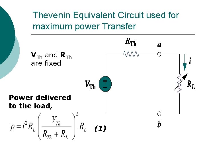
Thevenin Equivalent Circuit Thevenin equivalent circuit is useful in finding the max. power a linear cct. can deliver to a load. ¡ The entire cct can be replaced by its Thevenin eq. except for the adjustable load. ¡

Thevenin Equivalent Circuit used for maximum power Transfer VTh and RTh are fixed Power delivered to the load, (1)

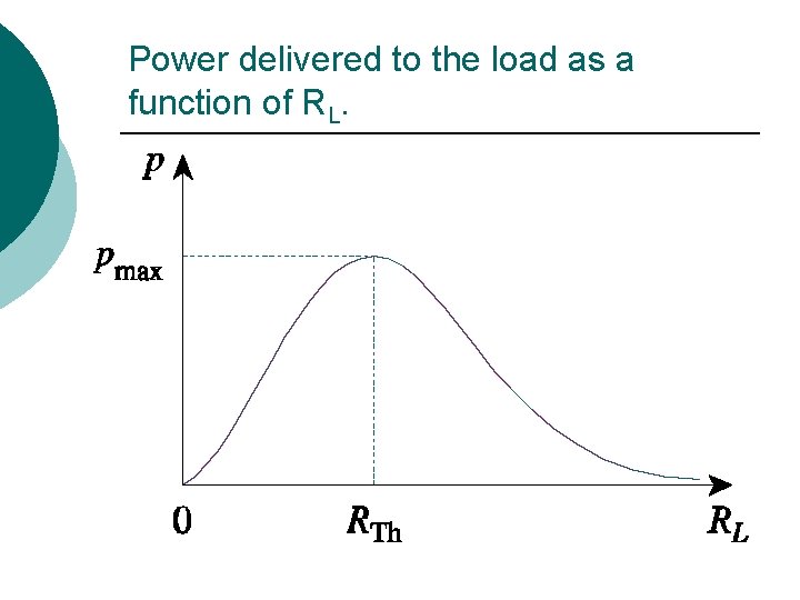
Power delivered to the load as a function of RL.

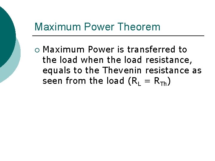
Maximum Power Theorem ¡ Maximum Power is transferred to the load when the load resistance, equals to the Thevenin resistance as seen from the load (RL = RTh)

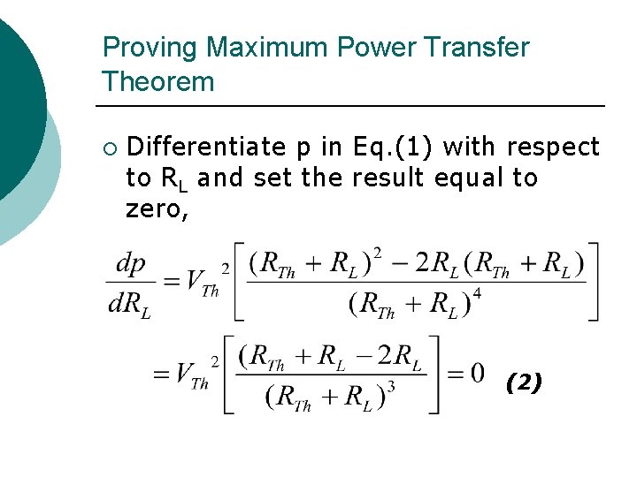
Proving Maximum Power Transfer Theorem ¡ Differentiate p in Eq. (1) with respect to RL and set the result equal to zero, (2)

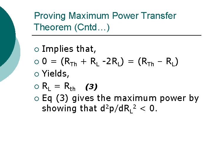
Proving Maximum Power Transfer Theorem (Cntd…) Implies that, ¡ 0 = (RTh + RL -2 RL) = (RTh – RL) ¡ Yields, ¡ RL = Rth (3) ¡ Eq (3) gives the maximum power by showing that d 2 p/d. RL 2 < 0. ¡

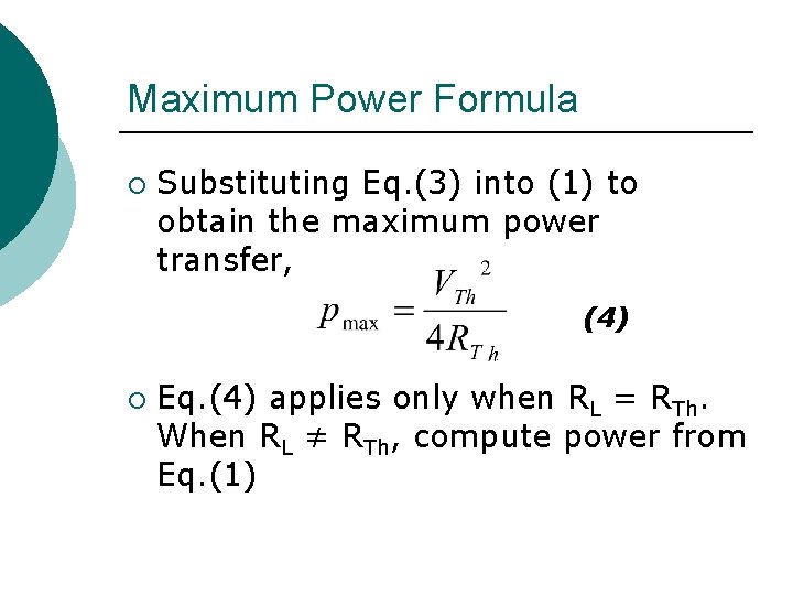
Maximum Power Formula ¡ Substituting Eq. (3) into (1) to obtain the maximum power transfer, (4) ¡ Eq. (4) applies only when RL = RTh. When RL ≠ RTh, compute power from Eq. (1)

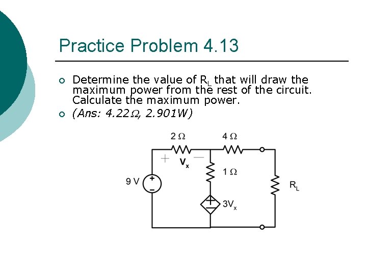
Practice Problem 4. 13 ¡ ¡ Determine the value of RL that will draw the maximum power from the rest of the circuit. Calculate the maximum power. (Ans: 4. 22 , 2. 901 W)

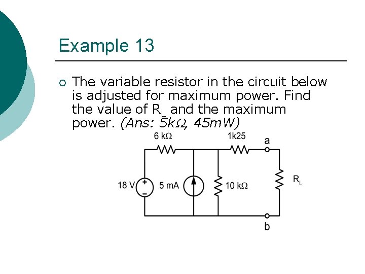
Example 13 ¡ The variable resistor in the circuit below is adjusted for maximum power. Find the value of RL and the maximum power. (Ans: 5 k , 45 m. W)

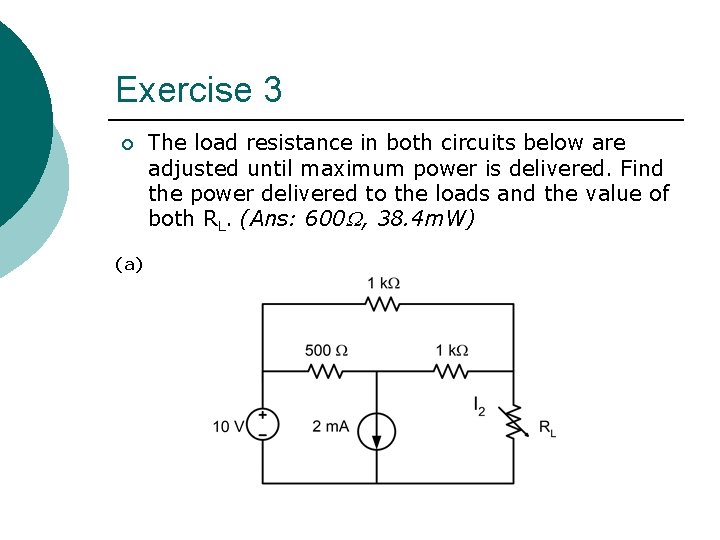
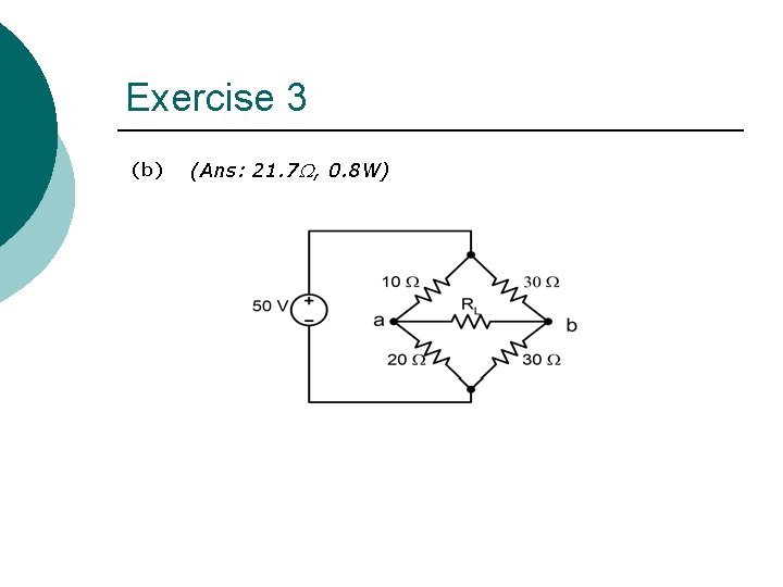
Exercise 3 ¡ (a) The load resistance in both circuits below are adjusted until maximum power is delivered. Find the power delivered to the loads and the value of both RL. (Ans: 600 , 38. 4 m. W)

Exercise 3 (b) (Ans: 21. 7 , 0. 8 W)