DBMS Entity Relationship ER Model The Entity Relationship
 Model")
DBMS Entity Relationship (E-R) Model
 Model 4 E-R Model Components u Entities l l u")
The Entity Relationship (E-R) Model 4 E-R Model Components u Entities l l u Attributes l l l u In E-R models an entity refers to the entity set. An entity is represented by a rectangle containing the entity’s name. Attributes are represented by ovals and are connected to the entity with a line. Each oval contains the name of the attribute it represents. Attributes have a domain -- the attribute’s set of possible values. Attributes may share a domain. Primary keys are underlined. Relationships

The Attributes of the STUDENT Entity

Basic E-R Model Entity Presentation
 Model 4 Classes of Attributes u A simple attribute cannot")
The Entity Relationship (E-R) Model 4 Classes of Attributes u A simple attribute cannot be subdivided. l u Examples: Age, Sex, and Marital status A composite attribute can be further subdivided to yield additional attributes. l Examples: – ADDRESS Street, City, State, Zip – PHONE NUMBER Area code, Exchange number
 Model 4 Classes of Attributes u A single-valued attribute can")
The Entity Relationship (E-R) Model 4 Classes of Attributes u A single-valued attribute can have only a single value. l u Examples: – A person can have only one social security number. – A manufactured part can have only one serial number. Multivalued attributes can have many values. l Examples: – A person may have several college degrees. – A household may have several phones with different numbers l Multivalued attributes are shown by a double line connecting to the entity.
 Model 4 Multivalued Attribute in Relational DBMS The relational DBMS")
The Entity Relationship (E-R) Model 4 Multivalued Attribute in Relational DBMS The relational DBMS cannot implement multivalued attributes. u Possible courses of action for the designer u l l Within the original entity, create several new attributes, one for each of the original multivalued attribute’s components. Create a new entity composed of the original multivalued attribute’s components

Splitting the Multivalued Attributes into New Attributes

A New Entity Set Composed of Multivalued Attribute’s Components
 Model u A derived attribute is not physically stored within")
The Entity Relationship (E-R) Model u A derived attribute is not physically stored within the database; instead, it is derived by using an algorithm. l Example: AGE can be derived from the data of birth and the current date. Figure: A Derived Attribute
 Model 4 Relationships A relationship is an association between entities.")
The Entity Relationship (E-R) Model 4 Relationships A relationship is an association between entities. u Relationships are represented by diamond-shaped symbols. u Figure : An Entity Relationship
 Model 4 A relationship’s degree indicates the number of associated")
The Entity Relationship (E-R) Model 4 A relationship’s degree indicates the number of associated entities or participants. A unary relationship exists when an association is maintained within a single entity. u A binary relationship exists when two entities are associated. u A ternary relationship exists when three entities are associated. u
 Model 4 Connectivity u The term connectivity is used to")
The Entity Relationship (E-R) Model 4 Connectivity u The term connectivity is used to describe the relationship classification (e. g. , one-to-one, one-tomany, and many-to-many). Figure : Connectivity in an ERD
 Model 4 Cardinality u Cardinality expresses the specific number of")
The Entity Relationship (E-R) Model 4 Cardinality u Cardinality expresses the specific number of entity occurrences associated with one occurrence of the related entity. Figure : Cardinality in an ERD
 Model 4 Relationship Participation u The participation is optional if")
The Entity Relationship (E-R) Model 4 Relationship Participation u The participation is optional if one entity occurrence does not require a corresponding entity occurrence in a particular relationship. u An optional entity is shown by a small circle on the side of the optional entity. Figure : An ERD With An Optional Entity

Figure : CLASS is Optional to COURSE Figure : COURSE and CLASS in a Mandatory Relationship
 Model 4 Weak Entities u A weak entity is an")
The Entity Relationship (E-R) Model 4 Weak Entities u A weak entity is an entity that l Is existence-dependent and l Has a primary key that is partially or totally derived from the parent entity in the relationship. u The existence of a weak entity is indicated by a double rectangle. u The weak entity inherits all or part of its primary key from its strong counterpart.

A Weak Entity in an ERD
 Model 4 Recursive Entities u A recursive entity is one")
The Entity Relationship (E-R) Model 4 Recursive Entities u A recursive entity is one in which a relationship can exist between occurrences of the same entity set. u A recursive entity is found within a unary relationship. Figure : An E-R Representation of Recursive Relationships
 Model 4 Composite Entities u A composite entity is composed")
The Entity Relationship (E-R) Model 4 Composite Entities u A composite entity is composed of the primary keys of each of the entities to be connected. u The composite entity serves as a bridge between the related entities. u The composite entity may contain additional attributes.

The M: N Relationship Between STUDENT and CLASS

A Composite Entity in the ERD

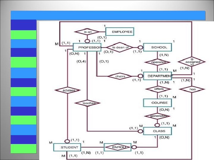
Developing an E-R Diagram 4 The process of database design is an iterative rather than a linear or sequential process. 4 It usually begins with a general narrative of the organization’s operations and procedures. 4 The basic E-R model is graphically depicted and presented for review. 4 The process is repeated until the end users and designers agree that the E-R diagram is a fair representation of the organization’s activities and functions.
 u College is divided")
Developing an E-R Diagram 4 B. D. College Database (1) u College is divided into several schools. Each school is administered by a dean. A 1: 1 relationship exists between DEAN and SCHOOL. u Each dean is a member of a group of administrators (ADMINISTRATOR). Deans also hold professorial rank and may teach a class (PROFESSOR). Administrators and professors are also Employees.
 Each school is composed")
Developing an E-R Diagram 4 B. D. College Database (2) Each school is composed of several departments. u The smallest number of departments operated by a school is one, and the largest number of departments is indeterminate (N). u Each department belongs to only a single school. u Figure : The First B. D. College ERD Segment
 u Each department offers")
Developing an E-R Diagram 4 B. D. College Database (3) u Each department offers several courses. Figure : The Second B. D. College ERD Segment
 A department may offer")
Developing an E-R Diagram 4 B. D. College Database (4) A department may offer several sections (classes) of the same course. u A 1: M relationship exists between COURSE and CLASS. u CLASS is optional to COURSE u Figure : The Third B. D. College ERD Segment
 Each department has many")
Developing an E-R Diagram 4 B. D. College Database (5) Each department has many professors assigned to it. u One of those professors chairs the department. Only one of the professors can chair the department. u DEPARTMENT is optional to PROFESSOR in the “chairs” relationship. u Figure : The Fourth B. D. College ERD Segment
 Each professor may teach")
Developing an E-R Diagram 4 B. D. College Database (6) Each professor may teach up to four classes, each one a section of a course. u A professor may also be on a research contract and teach no classes. u Figure : The Fifth B. D. College ERD Segment
 A student may enroll")
Developing an E-R Diagram 4 B. D. College Database (7) A student may enroll in several classes, but (s)he takes each class only once during any given enrollment period. u Each student may enroll in up to six classes and each class may have up to 35 students in it. u STUDENT is optional to CLASS. u Figure : The Sixth B. D. College ERD Segment
 Each department has several")
Developing an E-R Diagram 4 B. D. College Database (8) Each department has several students whose major is offered by that department. u Each student has only a single major and associated with a single department. u Figure : The Seventh B. D. College ERD Segment
 Each student has an")
Developing an E-R Diagram 4 B. D. College Database (9) Each student has an advisor in his or her department; each advisor counsels several students. u An advisor is also a professor, but not all professors advise students. u Figure : The Eighth B. D. College ERD Segment

Developing an E-R Diagram Entities for the B. D. College Database 4 SCHOOL 4 COURSE 4 DEPARMENT 4 CLASS 4 EMPLOYEE 4 ENROLL (Bridge between STUDENT and CLASS) 4 PROFESSOR 4 STUDENT

Components of the E-R Model

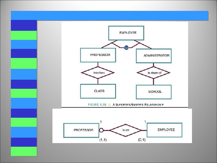
Extended E-R Features: Specialization 4 Top-down design process; we designate subgroupings within an entity set that are distinctive from other entities in the set. 4 These subgroupings become lower-level entity sets that have attributes or participate in relationships that do not apply to the higher-level entity set. 4 Depicted by a triangle component labeled ISA (E. g. customer “is a” person). 4 Attribute inheritance – a lower-level entity set inherits all the attributes and relationship participation of the higher-level entity set to which it is linked.

Specialization Example

Extended ER Features: Generalization 4 A bottom-up design process – combine a number of entity sets that share the same features into a higherlevel entity set. 4 Specialization and generalization are simple inversions of each other; they are represented in an E-R diagram in the same way. 4 The terms specialization and generalization are used interchangeably.
 4 Can have multiple specializations of an entity set")
Specialization and Generalization (Cont. ) 4 Can have multiple specializations of an entity set based on different features. 4 E. g. permanent_employee vs. temporary_employee, in addition to officer vs. secretary vs. teller 4 Each particular employee would be ua member of one of permanent_employee or temporary_employee, uand also a member of one of officer, secretary, or teller 4 The ISA relationship also referred to as superclass subclass relationship

Aggregation n Consider the ternary relationship works_on n Suppose we want to record managers for tasks performed by an employee at a branch
 4 Relationship sets works_on and manages represent overlapping information u Every")
Aggregation (Cont. ) 4 Relationship sets works_on and manages represent overlapping information u Every manages relationship corresponds to a works_on relationship u However, some works_on relationships may not correspond to any manages relationships l So we can’t discard the works_on relationship 4 Eliminate this redundancy via aggregation u Treat relationship as an abstract entity u Allows relationships between relationships u Abstraction of relationship into new entity 4 Without introducing redundancy, the following diagram represents: u An employee works on a particular job at a particular branch u An employee, branch, job combination may have an associated manager

E-R Diagram With Aggregation

Summary of Symbols Used in E-R Notation
- Slides: 44