Database Management Systems Course Objectives To understand purpose

Database Management Systems

Course Objectives • To understand purpose of database management system • Apply concepts like database design and database languages in managing data • Importance of normalization in dbms and SQL in implementation of database access • Knowledge of transaction control , recovery strategies , storage and indexing etc

Course Outcomes
, 3 rd Edition,")
Text Book 1. Database Management Systems, Raghurama Krishnan, Johannes Gehrke (2007), 3 rd Edition, Tata Mc. Graw-Hill, New Delhi, India 2. Database System Concepts Abraham Silberschatz, Henry F. Korth, S. Sudarshan (2010), 6 th Edition, Mc. Graw-Hill, New Delhi, India.

Roles • Data Engineer • Data Scientist etc

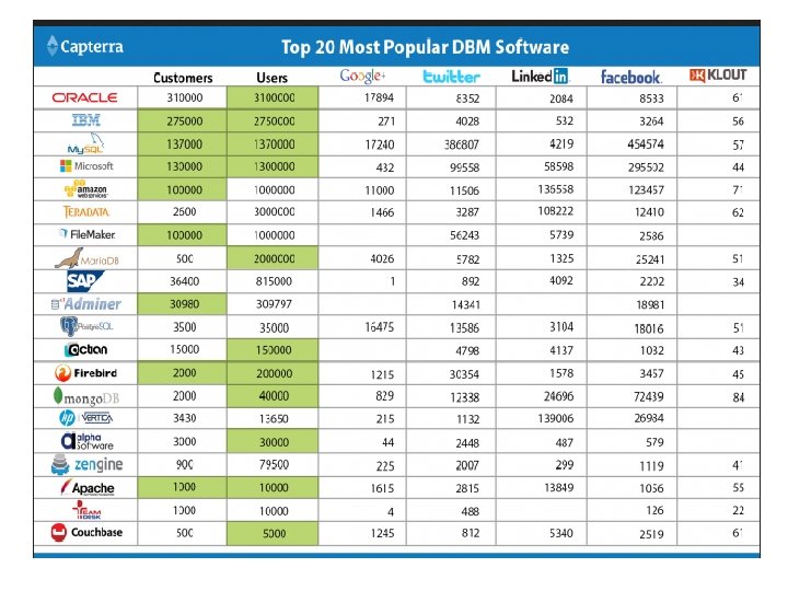
History of database systems • • • Integrated Data Store, First general purpose DBMS by charles bachman at General Electric. [Network Model] IBM’s Information Management System(IMS)[hierachial data model] SABRE system for making airline reservations By American airlines and IBM In 1970, at IBM’s San Jose Research laboratory proposed relational data model In 1980’s, SQL for relational databases by IBM Database transaction management james gray 1999 IBM’s DB 2, Oracle 8, Informix UDS ERP and MRP DBMS with internet Multimedia databases, streaming data, digital libraries , NASA’s earth observation system project Decision making and mining data repositories

Introduction to database management systems • Data: Data represents known facts or raw information in unorganized form (such as alphabets or numbers or symbols ). • Database: Database is a organized collection of data describing the activities of one or more related organizations. • Database management system(DBMS) is a software designed to assist in storing, maintaining and utilizing large collections of data. or A database-management system (DBMS) is a computer-software application which interacts with end-users, other applications, and the database itself to access, update, manage and analyze data with the help of set of application programs.

Advantages of Database management systems • • • Data Independence Efficient data access Data integrity and security Data administration Concurrent access and crash recovery Reduced application development time

Database systems applications

Database systems Vs file systems • File storage refers to a collection of operating system files. • DBMS features to manage the data in a robust and efficient manner.

Advantages of dbms over file system • No redundant data – Redundancy removed by data normalization • Data Consistency and Integrity – data normalization takes care of it too • Secure – Each user has a different set of access • Privacy – Limited access • Easy access to data • Easy recovery • Flexible

View of data • Abstraction • Data Abstraction • Instance and schema

• Abstraction : Hiding unnecessary details from the user and providing abstract view of data which is required to users. • Data Abstraction: Database systems are made-up of complex data structures. To ease the user interaction with database, the developers hide internal irrelevant details from users. This process of hiding irrelevant details from user is called data abstraction.

Schema • Design of a database is called schema. • 3 types: – Physical schema – Logical schema – View schema

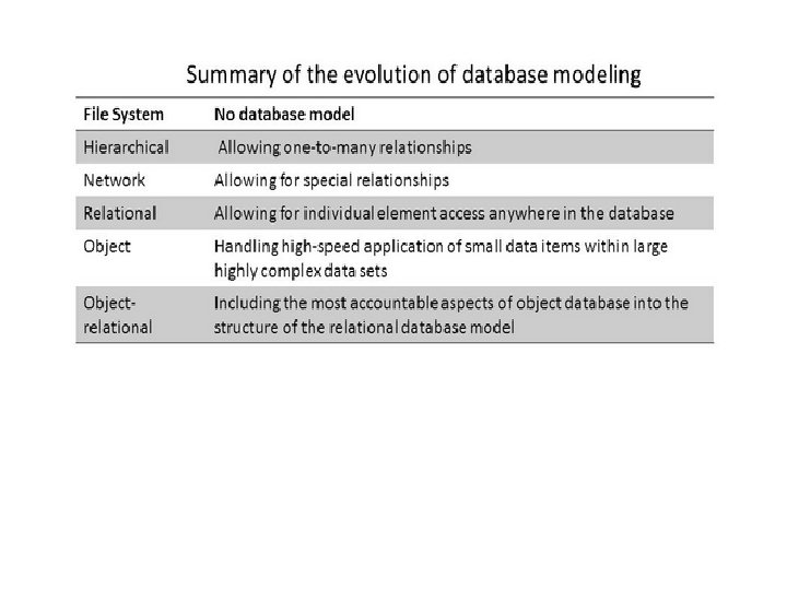
Data models • Data models determines the logical structure of a database • A Data Model is a logical structure of Database. It describes the design of database to reflect entities, attributes, relationship among data, constrains etc.

Data models • • Relational data model Entity – relationship model Hierarchical data model Network model Object oriented model Object relational model Semi structured data model Flat data model

Hierarchical data model • A hierarchical database model is a data model in which the data is organized into a tree-like structure. The data is stored as records which are connected to one another through links. • A record is a collection of fields, with each field containing only one value.

Example for hierarchical model

Example of hierarchical model

Hierarchical model

Network model • In the network model, entities are organized in a graph, in which some entities can be accessed through several paths.

Network data model example

Example for network model

Object oriented data model • This data model is another method of representing real world objects. • It considers each object in the world as objects and isolates it from each other. • It groups its related functionalities together and allows inheriting its functionality to other related sub-groups.

Object oriented model
, or object-relational database management system")
Object relational data model • An object-relational database (ORD), or object-relational database management system (ORDBMS), is a database management system (DBMS) similar to a relational database, but with an object-oriented database model: objects, classes and inheritance are directly supported in database schemas and in the query language

Semi structured data model: The semi-structured data model is designed as an evolution of the relational data model that allows the representation of data with a flexible structure. Semi-structured data model is model where schema is part of data
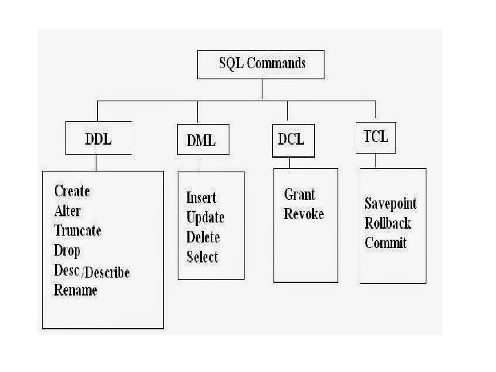

• Select – Unique – Distinct – Count – As – In – Sum – IS NULL – IS NOT NULL – ORDER BY – AND, OR

Database users and administration • Database users 1. 2. 3. 4. 5. Application Programmers Sophisticated users Specialized users Stand-alone users Native Users

Database administrators • Responsibilities of DBA: – Installing and upgrading DBMS servers – Design and implementation of databases – Schema definition , storage structure, access method definition – Performance Tuning – Migrate database servers – Backup and recovery – Security – Documentation etc

Types of database administrators • • • Administrative DBA Development DBA Database Architect Data warehouse DBA Application DBA OLAP DBA

Transaction management • • • • Transaction Partial transactions Concurrent execution of transactions Locking protocol Locks Shared locks Exclusive locks Incomplete transactions System crashes Log Write Ahead Log (WAL) Checkpoint Periodic checkpoints

Introduction to database design Database design process steps • • • Requirement Analysis Conceptual database design Logical database design Schema refinement Physical database design Application and security design

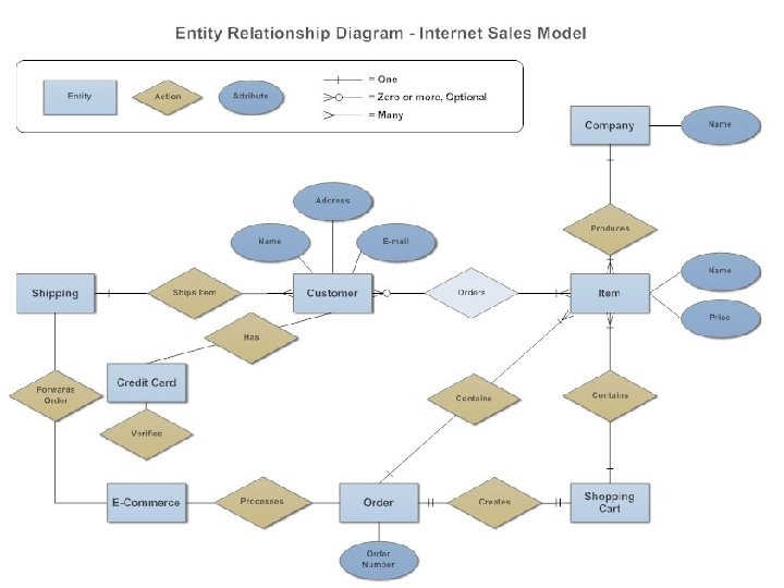
E -R diagrams • The E-R data model allows us to describe the data involved in a real-world enterprise in terms of objects and their relationships and is widely used to develop an initial database design.

entities • An entity is an object in the real world that is distinguishable from other objects. • An Entity can be any object, place, person or class. • an entity is represented using rectangles. Employee Works for Department

Weak entity is an entity that depends on another entity. Weak entity doesn't have key attribute of their own. Double rectangle represents weak entity.

attributes • An Attribute describes a property or characteristic of an entity. For example, Name, Age, Address etc can be attributes of a Student. An attribute is represented using eclipse

Types of attributes • Key attribute • Composite attributes • Derived attributes

relationships • A Relationship describes relations between entities. Relationship is represented using diamonds • Relationship is an association among 2 or more entities • There are three types of relationship that exist between Entities. • Binary Relationship • Recursive Relationship • Ternary Relationship

relationship sets • Collection of set of similar relationships is called a relationship set.

additional features of the E -R model • • • Key constraints for ternary relationships Participation constraints(partial and complete) Class hierarchies Aggregation

conceptual design with the E-R model • • Entity versus attribute Entity versus relationship Binary versus ternary relationships Aggregation versus ternary relationships

conceptual design for large enterprises

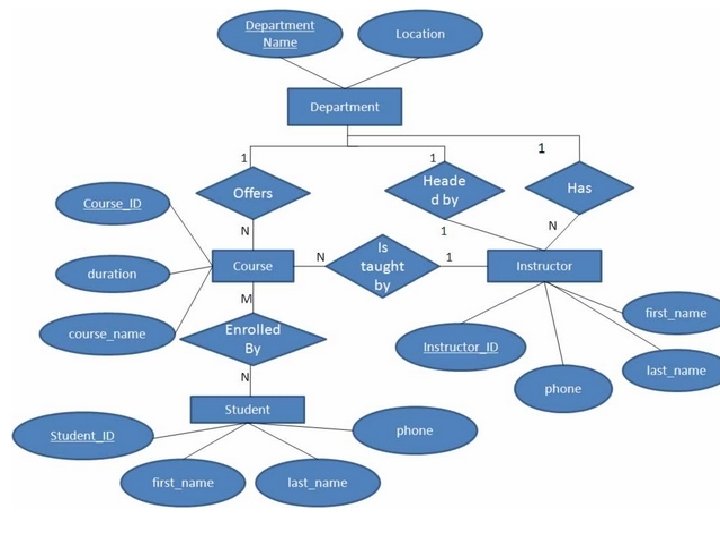
• • • A college contains many departments Each department can offer any number of courses Many instructors can work in a department An instructor can work only in one department For each department there is a Head An instructor can be head of only one department Each instructor can take any number of courses A course can be taken by only one instructor A student can enroll for any number of courses Each course can have any number of students

• • • Step 1 : Identify the Entities Stem 2 : Identify the relationships Step 3: Identify the key attributes Step 4: Identify other relevant attributes Step 5: Draw complete ER diagram

• Step 1 : Identify the Entities What are the entities here? From the statements given, the entities are • Department • Course • Instructor • Student

Stem 2 : Identify the relationships • One department offers many courses. But one particular course can be offered by only one department. hence the cardinality between department and course is One to Many (1: N) • One department has multiple instructors. But instructor belongs to only one department. Hence the cardinality between department and instructor is One to Many (1: N) • One department has only one head and one head can be the head of only one department. Hence the cardinality is one to one. (1: 1) • One course can be enrolled by many students and one student can enroll for many courses. Hence the cardinality between course and student is Many to Many (M: N) • One course is taught by only one instructor. But one instructor teaches many courses. Hence the cardinality between course and instructor is Many to One (N : 1)

• Step 3: Identify the key attributes • "Departmen_Name" can identify a department uniquely. Hence Department_Name is the key attribute for the Entity "Department". • Course_ID is the key attribute for "Course" Entity. • Student_ID is the key attribute for "Student" Entity. • Instructor_ID is the key attribute for "Instructor" Entity.

• Step 4: Identify other relevant attributes • For the department entity, other attributes are location • For course entity, other attributes are course_name, duration • For instructor entity, other attributes are first_name, last_name, phone • For student entity, first_name, last_name, phone

• A typical example could be entities Customer, Order, and Product. • An instance of the Customer entity is identified by a unique customer number, • an instance of the Order entity is identified by a unique order number, and • an instance of the Product entity is identified by a unique product number.
- Slides: 56