Database Design The Entity Relationship Model Chapter 8

Database Design – The Entity Relationship Model Chapter 8

Project – Design a Database
 data model has existed over 35")
Entities, Attributes, and Relationships The entity relationship (ER) data model has existed over 35 years. An entity is like a noun: it is a person, place, thing, or event An attribute is a property of an entity A relationship is an association between entities

Database Keys PRIMARY KEY Primary Key is a unique and non-null key which identify a record uniquely in table. A table can have only one primary key. FOREIGN KEY A Foreign Key creates a link between tables. It references the primary key in another table and links it. For example, the Dept. ID in the Employee table is a foreign key −

PK AND FK relationship Above, you can see the two tables. The Foreign Key of the Employee table is the Primary Key of the Department table.

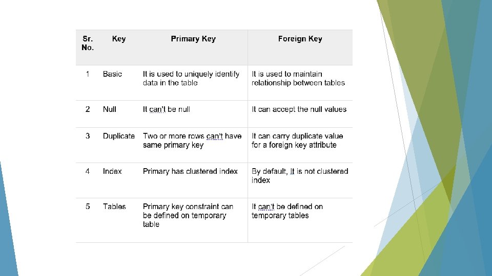
DIFFERENCE BETWEEN PRIMARY KEY AND FOREIGN KEY In the relational database key is the most important element to maintain the relationship between two tables or to uniquely identify data from the table. Primary key is used to identify data uniquely therefore two rows can’t have the same primary key. It can’t be null. On the other hand, foreign key is used to maintain relationship between two tables. Primary of a table act as foreign key in the other table. Foreign key in a table enforces Referential Integrity constraint. It can be more than one in the table.

CANDIDATE KEY Candidate key is also a unique key to identify a record uniquely in a table but a table can have multiple candidate keys. Each table has only a single primary key. Each relation may have one or more candidate key. One of these candidate key is called Primary Key. Each candidate key qualifies for Primary Key. Therefore, candidates for Primary Key is called Candidate Key. Candidate key can be a single column or combination of more than one column. A minimal super key is called a candidate key. Example Employee. ID and Employee. Email, both can be a Primary key; and both are candidate keys. Select any of the as Primary Key for your table, since a table can have only a single Primary Key.

Another example Above, Student_ID, Student_Enroll and Student_Email are the candidate keys. They are considered candidate keys since they can uniquely identify the student record. Both Primary Key and Candidate key are used to get records from tables. These keys are also used to create relationship between tables. Primary Key and Candidate key both are used to identify records uniquely in a table.

DIFFERENCE BETWEEN PRIMARY KEY AND CANDIDATE KEY

COMPOSITE KEY A primary key having two or more attributes is called composite key. It is a combination of two or more columns. An example can be − Here our composite key is Order. ID and Product. ID −

ANOTHER EXAMPLE Above, our composite keys are Student. ID and Student. Enroll. No. The table has two attributes as primary key. Therefore, the Primary Key consisting of two or more attribute is called Composite Key.

SECONDARY KEY What is a Secondary Key is the key that has not been selected to be the primary key. However, it is considered a candidate key for the primary key. Therefore, a candidate key not selected as a primary key is called secondary key. Candidate key is an attribute or set of attributes that you can consider as a Primary key. Note: Secondary Key is not a Foreign Key.

SECONDARY KEY EXAMPLE Student_ID, Student_Enroll and Student_Email are the candidate keys. They are considered candidate keys since they can uniquely identify the student record. Select any one of the candidate key as the primary key. Rest of the two keys would be Secondary Key. Let’s say you selected Student_ID as primary key, therefore Student_Enroll and Student_Email will be Secondary Key (candidates of primary key).

ANOTHER SECONDARY KEY EXAMPLE Above, Employee_ID, Employee_No and Employee_Email are the candidate keys. They uniquely identify the Employee record. Select any one of the candidate key as the primary key. Rest of the two keys would be Secondary Key.

SUPER KEY Definition of Super Key in DBMS: A super key is a set of one or more attributes (columns), which can uniquely identify a row in a table. People get confused between super key and candidate key. How candidate key is different from super key? Candidate keys are selected from the set of super keys, the only thing we take care while selecting candidate key is: It should not have any redundant attribute. That’s the reason they are also termed as minimal super key.
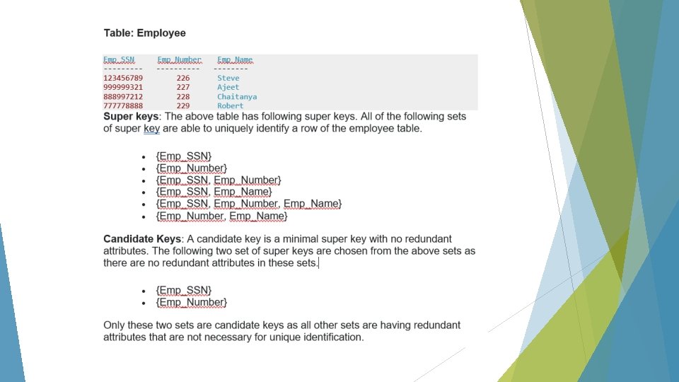

Super key vs Candidate Key First all the candidate keys are super keys. This is because the candidate keys are chosen out of the super keys. Second, how do we choose candidate keys from the set of super keys? We look for those keys from which we cannot remove any fields. In the above example, we have not chosen {Emp_SSN, Emp_Name} as candidate key because {Emp_SSN} alone can identify a unique row in the table and Emp_Name is redundant.

ALTERNATE KEYS Alternate Key or Secondary Key is a key that has not been selected to be the primary key but are candidate keys. However, it is considered a candidate key for the primary key. In other words, a candidate key not selected as a primary key is called alternate or secondary key.

ALTERNATE KEY EXAMPLE

ANOTHER ALTERNATE KEY EXAMPLE
 Relational database design documentation generally identifies")
Documenting a Relational Database Design (1 of 3) Relational database design documentation generally identifies the following items: The attributes needed for each normalized entity The primary key field for each entity The indexes and other properties needed to describe each attribute and entity The proper one-to-many relationships between the entities One approach for expanding the definition of each table uses an extended notation called Database Design Language (DBDL) DBDL fields expands the definition of an entity by specifying different types of key
 The expanded rules for defining tables")
Documenting a Relational Database Design (2 of 3) The expanded rules for defining tables and their keys using DBDL are as follows: Tables (relations), columns (attributes), and primary keys are written by first listing the table name and then, in parentheses, listing the columns that make up the table. The column(s) that make up the primary key are underlined Alternate keys are identified by the abbreviation AK, followed by the column(s) that make up the alternate key These A are all candidate keys not chosen to be a primary key. candidate key is a simple or composite key that is unique and minimal. A composite key is composed of two or more attributes and must be minimal. (i. e. Last Name and Department ID) Secondary keys are identified by the abbreviation SK, followed by the column(s) that make up the secondary key, they are usually an attributed used for retrieval purposes Foreign keys are identified by the abbreviation FK, followed by the column(s) that make up the foreign key. Foreign keys are followed by an arrow pointing to the table identified by the foreign key. They reference a primary key in another table and must be the same data type.
")
Documenting a Relational Database Design (3 of 3)

Database Design Examine the requirements and identify the entities, or objects, involved Identify a unique identifier for each entity Identify the attributes for all the entities Identify the functional dependencies that exist among the attributes Use the functional dependencies to identify the tables Determine and implement relationships among the entities One-to-many Foreign key Many-to-many
 Diagrams (1 of 7) An E-R diagram uses rectangles to represent the")
Entity-Relationship (E-R) Diagrams (1 of 7) An E-R diagram uses rectangles to represent the entities (tables) and lines to represent the relationships between the tables Provides a more visual representation of the entities, attributes, and relationships between the entities than DBDL notation A one-to-many relationship between two tables is created with a field that is common to each table The linking field in the table on the “many” side of a one-to-many relationship is called the foreign key field A foreign key field is never also the one-field primary key field for a particular table
 Diagrams (2 of 7)")
Entity-Relationship (E-R) Diagrams (2 of 7)
 Diagrams (3 of 7) Crow’s foot notation Symbol on the side of")
Entity-Relationship (E-R) Diagrams (3 of 7) Crow’s foot notation Symbol on the side of the “many” entity that resembles a crow’s foot Specific attributes for each entity are not listed within each entity rectangle
 Diagrams (4 of 7) Another popular representation of an E-R diagram is")
Entity-Relationship (E-R) Diagrams (4 of 7) Another popular representation of an E-R diagram is the one used by Microsoft Access Displays the number 1 and the infinity symbol at the ends of the link line to identify the two sides of a one-to-many relationship The 1 and infinity symbols are only displayed on one-to-many relationships that enforce referential integrity Recall that referential integrity prevents the creation of orphan records, records in the “many” side of a relationship that do not have a matching value in the “one” side of the relationship In Access, the link line specifically points to the fields that create the relationship instead of pointing to the edge of the entity’s rectangle in general
 Diagrams (5 of 7)")
Entity-Relationship (E-R) Diagrams (5 of 7)
 Diagrams (6 of 7) Another E-R diagram in Access shows the “one”")
Entity-Relationship (E-R) Diagrams (6 of 7) Another E-R diagram in Access shows the “one” and infinity symbols on each link line indicating that referential integrity is enforced on every relationship Another term that describes relational databases is cardinality In general, cardinality refers to the number of items in a set In the context of a database, cardinality refers to the uniqueness of data values contained in a single field High cardinality means that a field contains many unique or uncommon values, and low cardinality means that a field contains only a few unique values
 Diagrams (7 of 7)")
Entity-Relationship (E-R) Diagrams (7 of 7)
 (1 of 5) Another way to document a relational database")
The Entity-Relationship Model (ERM) (1 of 5) Another way to document a relational database is the entity-relationship model The E-R model (also called ERM) uses rectangles for entities and diamonds for relationships The lines that connect the entities contain notation to identify whether they are on the “one” or “many” side of a relationship
 (2 of 5)")
The Entity-Relationship Model (ERM) (2 of 5)
 (3 of 5) An ERM can also be used to")
The Entity-Relationship Model (ERM) (3 of 5) An ERM can also be used to identify a “many-to-many” relationship between two tables
 (4 of 5) Many-to-many relationships cannot be directly created between")
The Entity-Relationship Model (ERM) (4 of 5) Many-to-many relationships cannot be directly created between two tables in a relational database management system To implement a many-to-many relationship in a relational database, you must insert a physical entity between the two tables to link them together In the ERM, the middle entity is called a composite entity In a physical implementation of the relational database, the composite entity is called a junction table The junction table serves on the “many” side of a one-to-many relationship with each of the two original tables
 (5 of 5)")
The Entity-Relationship Model (ERM) (5 of 5)
- Slides: 39