
Data Plane Testing on USN ESnet and Internet

- Slides: 14
Data Plane Testing on USN, ESnet, and Internet 2 Networks ESCC/Internet 2 Joint Techs Summer Meeting July 16, 2007 Fermi Lab Batavia, Illinois US Dept. of Energy Office of Science Tom Lehman (USC/ISI) Nasir Ghani (Tennessee Tech) Chin Guok (ESnet) Nagi Rao (ORNL) John Vollbrecht (Internet 2) John Moore (MCNC) Hybrid MLN
Outline • • • Dataplane testing configuration Dataplane test data Dataplane simulation Dataplane test conclusions Future Work 2
Hybrid Network Data Planes • Basic premise of hybrid networks is the availability of both best effort routed service and deterministic dedicated resource paths, i. e. , circuits • There are many technologies available over which to construct these circuits – IP router-based Multiprotocol Label Switching (MPLS) Label Switched Paths (LSPs) “circuits” – Ethernet VLAN based “circuits” – SONET/SDH TDM “circuits” – Wavelength Division Multiplexing (WDM) “circuits” 3
What Data Plane Technologies to Use? • What do you want to do with your circuits? – Dedicated bandwidth connections for deterministic file transfers? – Dedicated bandwidth & low jitter for instrument control or interactive applications? – Connector backhaul to your IP Network? – Traffic engineering of your IP Network? • Dynamic router-to-router circuits for traffic cut thru? – Computer to Computer communications? • Processor to memory? block data storage system access? – Setting up application specific topologies to create & optimize distributed application or data storage systems? 4
Data Plane Testing • Test characteristics/performances of “circuits” constructed via different technologies; and also “end-to-end paths” constructed via concatenation of individual circuits • Questions – – What is difference between the different technologies? How well does the concatenation/stitching work? How well does policing/shaping work at the edge? What happens to a flow that is policed/shaped at the ingress edge by the time it exits the egress edge? 5
Data Plane Testing Data Paths Across: • ESnet • USN • Abilene • Internet 2 Network • DRAGON http: //hybrid. east. isi. edu 6
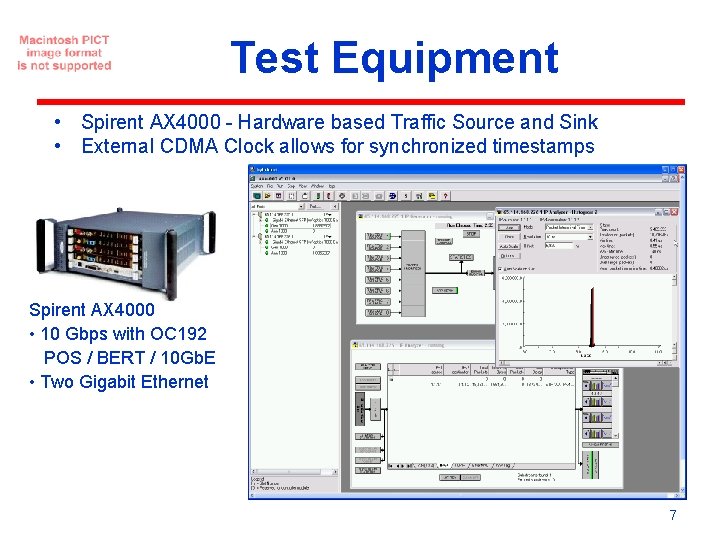
Test Equipment • Spirent AX 4000 - Hardware based Traffic Source and Sink • External CDMA Clock allows for synchronized timestamps Spirent AX 4000 • 10 Gbps with OC 192 POS / BERT / 10 Gb. E • Two Gigabit Ethernet 7
Data Collection • Approximately 75 individual tests (generally a unique path) – tests were sourced from 1 Gbps interfaces, some from 10 Gbps – some of the measured flows had cross traffic introduced • Tests generally included 9 measured data collection runs – 64, 500, 8000 byte MTU – 100, 500, 800 Mbps for 1 Gbps paths – 1, 5, 8 Gbps for 10 Gbps paths • For each test run, the following data was collected: – – – average datarate total packet loss average latency jitter profile (histogram) transfer delay (histogram) 8
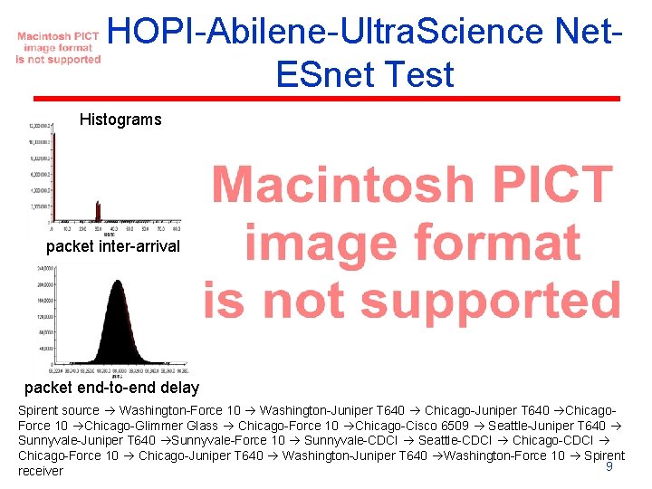
HOPI-Abilene-Ultra. Science Net. ESnet Test Histograms packet inter-arrival packet end-to-end delay Spirent source Washington-Force 10 Washington-Juniper T 640 Chicago-Juniper T 640 Chicago. Force 10 Chicago-Glimmer Glass Chicago-Force 10 Chicago-Cisco 6509 Seattle-Juniper T 640 Sunnyvale-Juniper T 640 Sunnyvale-Force 10 Sunnyvale-CDCI Seattle-CDCI Chicago-Force 10 Chicago-Juniper T 640 Washington-Juniper T 640 Washington-Force 10 Spirent 9 receiver
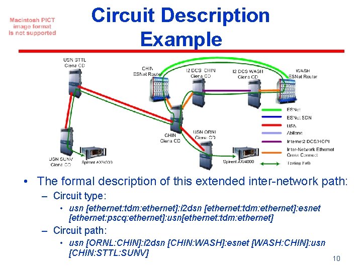
Circuit Description Example • The formal description of this extended inter-network path: – Circuit type: • usn [ethernet: tdm: ethernet]: i 2 dsn [ethernet: tdm: ethernet]: esnet [ethernet: pscq: ethernet]: usn[ethernet: tdm: ethernet] – Circuit path: • usn [ORNL: CHIN]: i 2 dsn [CHIN: WASH]: esnet [WASH: CHIN]: usn [CHIN: STTL: SUNV] 10
Modeling & Simulation OPNET Modeler. TM Environment Overview • Discrete event simulation • GUI interface, high re-use • Full C/C++ interface • Hierarchical modeling: Subnet-node-link-process “In-House” Development • MPLS/GMPLS control: RSVP-TE, OSPF-TE, PCE • Layer 2/3 data plane: IP/MPLS, VLAN • Full Layer 1 support: DWDM, SONET, GFP • Model any networks 11
Test Plans, Reports, and Data Repositories • Test Report and Plans – http: //hybrid. east. isi. edu Data. Plane Testing and Analysis • Raw data repositories – http: //www. csm. ornl. gov/ultranet/Spirent. Meas urements/ – http: //hpn. east. isi. edu/dataplane/sprint-testdata/ 12
Summary/Conclusions • All of the tested networking technologies (PSC, L 2 SC, TDM, LSC) and networks (ESnet, USN, Abilene, HOPI, DRAGON) performed well both individually and when concatenated together • There are some key differences observed between the various networking layer technologies when driven at or close to bottleneck capacity – Qo. S techniques applied to router MPLS or Ethernet switched paths exhibited notably different delay behaviors versus dedicated circuit-paths (TDM) – TDM-based infrastructures is most germane for applications requiring stringent guarantees on latency, jitter, and bandwidth protection • Inter-layer cross-connections can be achieved in a reasonable manner by “stitching” together different network layer technologies. – Ethernet VLANs presents the least problematic demarc (automated techniques needed to coordinate VLAN tag space) • Future Work – impact of ingress traffic "burstiness” on end-to-end delay and loss profiles, i. e. , both for reference and interfering cross-traffic streams. – best techniques for ingress policing and transit node Qo. S – vendor interoperability testing – additional network testing 13
Thank-You Questions & Comments ? Tom Lehman tlehman@east. isi. edu 14