Data formats or Instruction formats of 8086 The


 Register to/from Memory with Displacement : This type of instruction format contains one")
 Immediate operand to register")

 data is given in the instruction itself. Ex:")

 Based Indexed addressing : registers The Offset address of data is the sum")
 Relative Indexed addressing: The Offset address is the sum of the content of")


")
 Inter segment mode : In this mode, the destination address lies in")


- Slides: 64
Data formats or Instruction formats of 8086: The instruction format of 8086 has one or more number of fields associated with it. The first filled is called operation code field or opcode field, which indicates the type of operation. The instruction format also contains other fields known as operand fields. There are six general formats of instructions in 8086 instruction set. One byte Instruction Register to/from memory with no displacement Register to/from Memory with Displacement Immediate operand to register immediate operand to memory with 16 -bit displacement
One byte Instruction: This format is only one byte long and may have the implied data or register operands. The least significant 3 bits of the opcode are used for specifying the register operand, if any. Otherwise, all the eight bits form an opcode and the operands are implied. For example: 1 1 1 0 0 0 CLC : clear carry This is an operation without any operand, which clear the carry flag bit. Adjust for addition AAA 00110111 Here the operand to this instruction is implicit and it take the contents of register AL.
Register to Register : This format is 2 bytes long. The first byte of the code specifies the operation code and the width of the operand specifies by w bit. The second byte of the opcode shows the register operands and RIM field
Register to/from memory with no displacement : This format is also 2 bytes long and similar to the register to register format except for the MOD field.
d) Register to/from Memory with Displacement : This type of instruction format contains one or two additional bytes for displacement along with 2 -byte the format of the register to/from memory without displacement.
e) Immediate operand to register
ADDRESSING MODES OF 8086 The method of specifying data to be operated by an instruction is called as addressing mode. The different ways that a processor can access the data are referred to as addressing modes. 1. Immediate addressing 2. Direct addressing 3. Register addressing 4. Register Indirect addressing (a) Based addressing (b) Indexed addressing (c) Based Indexed addressing 5. Register Relative (a) Relative Based(b) Relative Indexed (c) Relative Based Indexed 6. Implicit addressing 7. Addressing modes for Control transfer / Branch Instructions (a) Intra segment mode (b) Inter segment mode 8. I/O port addressing
1. Immediate addressing: The operand (or) data is given in the instruction itself. Ex: MOV AX, 1234 H ADD AX, 4567 H 2. Direct addressing: The Offset address of operand or data is given in the instruction itself. Ex: MOV BX, [2000 H] ADD AX, [3000 H] Note: Effective address/ Offset address of data = 3000 H 20 -bit Physical address = DS * 10 + 3000 H 3. Register addressing: The data is available in any one of the general purpose registers. Ex: MOV AX, BX ADD AX, BX
4. Register Indirect addressing: The Offset address of data is available in any one of the Base / Index registers. (a) Based addressing: The Offset address of the data is available in any one of the Base registers BX or BP Ex: MOV AX, [BX] Offset address = BX 20 -bit physical address = DS*10 + BX (b) Indexed addressing: The Offset address of data is available in any one of the Index registers SI or DI Ex: MOV AX, [SI] Offset address = SI 20 -bit physical address = DS*10 + SI
(c) Based Indexed addressing : registers The Offset address of data is the sum of Base and Index Ex: MOV AX, [BX][SI] Offset address = BX+SI 20 -bit physical address = DS*10 + BX+SI 5. Register Relative addressing: The Offset address is formed by adding 8 -bit (or) 16 -bit signed Displacement to the content of Base / Index registers. (a) Relative Based addressing: The Offset address is the sum of the content of Base register BX or BP and 8 bit or 16 -bit signed Displacement Ex: 1. MOV AX, 25 H[BX] Offset address = BX+25 H 20 -bit physical address = DS*10 + BX+25 2. MOV AX, 1234 H[BX]
(b) Relative Indexed addressing: The Offset address is the sum of the content of Index register SI or DI and 8 bit or 16 -bit signed Displacement Ex: MOV AX, 48 H[SI] Offset address = SI+48 H 20 -bit physical address = DS*10 + SI+48 H (c) Relative Based Indexed addressing : The Offset address of data is the sum of contents of Base register , Index register and 8 bit or 16 -bit signed Displacement Ex: MOV AX, 1000 H[BX][SI] Offset address = BX+SI+1000 H 20 -bit physical address = DS*10 + BX+SI+1000 H
6. Implicit addressing: The instruction itself specifies the data to be operated. Ex: DAA - Decimal Adjust Accumulator after addition AAA - ASCII Adjust Accumulator after addition
7. I/O port addressing: I/O port addressing is used to access the I/O ports. (a) Fixed port addressing: The 8 -bit I/O port address is available in the instruction IN AL, 80 H ; It reads one byte of data from I/O port address 80 H to AL OUT 82 H, AL ; It sends one byte of data from AL to I/O port address 82 H (b) Variable port addressing: The 16 -bit I/O port address is available in DX register. Ex: MOV DX, 1234 H IN AL, DX OUT DX, AL In above instructions, the register DX contains address of I/O port.
8. Addressing modes for Control transfer / Branch Instructions 2 - types : (a) Intra segment mode (b) Inter segment mode (a) Intra-segment mode : In this mode, the destination address lies in the same Code segment. The address appears as an immediate displacement value. This displacement is computed relative to IP. Here IP is only modified. CS remains the same. Intra-segment direct: Ex: JMP SHORT label; label lies between -128 and +127. Ex: JMP LONG label; label lies between -32768 and +32767. Intra-segment indirect: Ex: JMP [BX];
(b) Inter segment mode : In this mode, the destination address lies in different Code segment. Here both CS and IP registers will be modified. Inter segment direct: JMP 5000 H: 2000 H CS: IP o Inter segment indirect: JMP [3000 H];
INSTRUCTION SET The 8086 Instruction set is classified as Data transfer instructions Arithmetic instructions Logic & Bit manipulation instructions Branch / Control transfer instructions String manipulation instructions Processor control instructions
DATA TRANSFER INSTRUCTIONS MOV: Copies data from source to destination. Source Immediate/Reg/Mem Dest Reg/Mem Ex: MOV AX, 1234 H MOV AX, BX MOV AX, [2000 H] MOV AX, [SI] MOV AX, 50 H[BX] PUSH: Pushes the content of source on to the stack. After the execution, SP is decremented by 2 and the source content is stored at stack top. Ex: PUSH AX SP SP-2 [SP] AX
POP: Pop a word from stack top to specified register The content of stack top is moved to destination & SP is incremented by 2 Ex: POP AX AX [SP] SP+2 XCHG : Exchange the contents of source and destination Ex: XCHG BX, AX XCHG [5000], AX IN: Read data from specified input port to Accumulator Ex: IN AL, 80 H ; It reads one byte of data from I/O port address 80 H to AL MOV DX, 1234 H IN AL, DX q
OUT: Send data from Accumulator to specified output port Ex: OUT 82 H, AL ; It sends one byte of data from AL to I/O port address 82 H MOV DX, 1234 H OUT DX, AL XLAT: Translate This translate instruction is used for finding out codes in code conversion problems, using lookup table technique. Ex: XLAT: Translate byte to AL. LEA: Load Effective Address Loads of the effective address formed by destination operand into the specified source register. Ex: LEA BX, ADR LEA SI, ADR[BX]
LDS/LES: Load pointer to DS or ES Load specified register and DS registers with contents of two words from the effective address Ex: LDS BX, 5000 H/ LES BX, 5000 H
LAHF: Load AH from lower byte of Flag SAHF: Store AH to lower byte of Flag PUSHF: PUSH Flags to stack POPF : POP Flags from stack
ARITHMETIC INSTRUCTIONS ADD: the content of source is added to the destination and result will be stored in destination. Ex: ADD AX, 0100 H ADD AX, BX ADD AX, [2000 H] ADD AX, [SI] ADD AX, 2000 H[BP] ADC: the content of source along with carry are added to the destination and result will be stored in destination. SUB: SBB: INC: Increases the contents of specified register or memory location by 1. DEC: Decreases the contents of specified register or memory location by 1.
CMP: it compares destination and source operands. If the destination < source then CF is set(1). If the destination > source then CF is reset(0). If the destination = source then ZF is set(1). Ex: CMP BX, 0100 H CMP [5000 H], 0100 H NEG: Negate It forms the 2’s complement of the specified destination in the instruction.
AAA: ASCII Adjust after Addition It is executed after an ADD instruction that adds two ASCII operands to give byte result in AL. AAA converts the result in AL into unpacked decimal digits. AAS : ASCII Adjust after Subtraction It is executed after SUB instruction that subtracts two ASCII operands to give byte result in AL. AAS converts the result in AL into unpacked decimal digits. AAM : ASCII adjust after Multiplication It is executed after MUL instruction that multiplies two unpacked operands to give byte result in AL. AAM converts the result in AL into unpacked decimal digits.
AAD : ASCII adjust before Division It converts two unpacked BCD digits in AH and AL to the equivalent packed binary number in AL. Ex: AX = 0508 AAD result in AL = 3 AH
DAA: Decimal Adjust after Addition It converts the result of addition of two packed BCD numbers to a valid BCD number. The result has to be in AL. If the lower nibble of AL>9 then it adds 06. If the higher nibble of AL>9 then it adds 60.
Ex:
DAS: Decimal Adjust after Subtraction It converts the result of subtraction of two packed BCD numbers to a valid BCD number. The result has to be in AL. If the lower nibble of AL>9 then it subtracts 06. If the higher nibble of AL>9 then it subtracts 60.
MUL: Unsigned Multiplication Multiplies the contents of AL or AX with an unsigned byte or word. The most significant word of the result is stored in DX and the least significant word of the result is stored AX. Ex: MUL BH; (AX ) (AL)*(BH) MUL CX; (DX) (AX)*(CX) IMUL: Signed Multiplication Multiplies the contents of AL or AX with an signed byte or word. The most significant word of the result is stored in DX and the least significant word of the result is stored AX. Ex: IMUL BH; (AX ) (AL)*(BH) IMUL CX; (DX) (AX)*(CX)
CBW: Convert Byte to Word It converts a signed byte to a signed word. It copies the sign bit of a byte to all the bits in the higher byte of the result word. CWD: Convert Word to Double word It copies sign bit of AX to all the bits of the DX register. DIV: Unsigned Division: It divides an unsigned word or double word by a 8 bit or 16 bit operand. The dividend must be in AX for 8 -bit operation and in DX: AX pair for 16 -bit operation. The quotient will be in AL or AX and the remainder will be in AH or DX. Ex: DIV BL AHAL/BL DIV BX DXAX/BX
IDIV: Signed Division It divides an signed word or double word by a 8 bit or 16 bit operand. The dividend must be in AX for 8 -bit operation and in DX: AX pair for 16 -bit operation. The quotient will be in AL or AX and the remainder will be in AH or DX. Ex: IDIV BL AHAL/BL IDIV BX DXAX/BX
LOGICAL INSTRUCTIONS AND: It performs bitwise AND operation on Source and Destination operands. Ex: AND AX, 0008 H AND AX, BX AND AX, [2000 H] AND [5000 H], DX OR: It performs bitwise OR operation on Source and Destination operands. XOR: It performs bitwise XOR operation on Source and Destination operands.
NOT: Logical invert It complements the content of a register or a memory location , bit by bit. Ex : NOT AX NOT [5000 H] TEST: Logical AND It performs bit wise logical AND operation on the two operands. Ex: TEST AX, BX TEST [0500 H], 06 H
SHL/SAL: Shift left/Shift Arithmetic left These instructions shift the operand word or byte bit by bit to the left and insert zeros in the newly introduced least significant bits. SHR: Shift Logical Right This instruction shift the operand word or byte bit by bit to the right and insert zeros in the newly introduced most significant bits. SAR: Shift Arithmetic right This instruction shift the operand word or byte bit by bit to the right and it inserts most significant of the operand in the newly introduced most significant bits.
ROL: Rotate Left without carry This instruction rotates the contents of destination operand to the left (bit wise) either by one or count specified in CL register, excluding carry ROR: Rotate Right without carry This instruction rotates the contents of destination operand to the right (bit wise) either by one or count specified in CL register, excluding carry RCL: Rotate Left through carry This instruction rotates the contents of destination operand to the left through carry (bit wise) either by one or count specified in CL register. RCR: Rotate Right through carry This instruction rotates the contents of destination operand to the right through carry (bit wise) either by one or count specified in CL register.
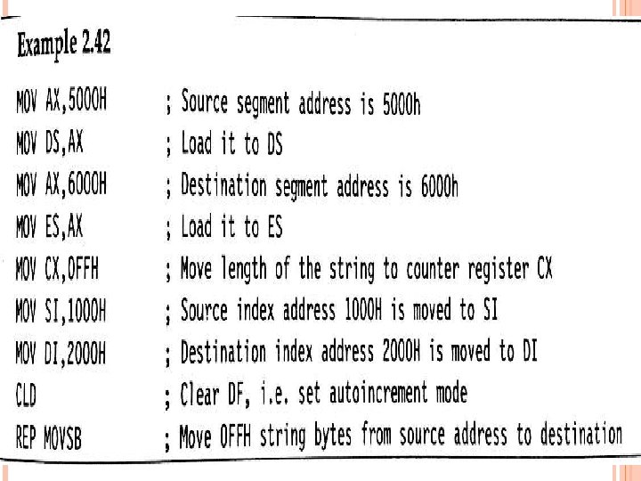
STRING MANIPULATION INSTRUCTIONS MOVSB/MOVSW: move string byte/word This instruction moves a string of bytes/words pointed by DS: SI pair to the memory location pointed by ES: DI pair. Each time it is executed, the index registers are automatically updated and CX is decremented. REP: Repeat Instruction Prefix It is used as a prefix to other instructions. The instruction to which the REP prefix is provided, is executed repeatedly until the CX register becomes zero. REPE/REPZ: Repeat operation while equal/zero REPNE/REPNZ: Repeat operation while not equal/not zero
CMPS: Compare String Byte or String Word It compares two strings stored in DS: SI and ES: DI. The length of the string must be stored in CX register. REP instruction prefix is used to repeat the operation till CX becomes zero.
SCAS: Scan String Byte or Word It scans a string of bytes or words for an operand byte or word specified in the register AL or AX. The string is pointed by ES: DI register pair. If a match to the specified operand is found in the string then execution stops and zero flag is set.
LODS: Load String Byte or String Word It loads AL/AX register by the content of a string pointed by DS: SI register pair. SI is modified automatically depending upon DF. STOS: Store String Byte or String Word It stores the content of AL/AX register to a location in the string pointed by ES: DI register pair. DI is modified automatically depending upon DF.
CONTROL TRANSFER/BRANCHING INSTRUCTIONS CALL: Unconditional Call It is used to call a subroutine/procedure from a main program. The address of the procedure may be specified directly or indirectly depending upon the addressing mode. On execution , it pushes the incremented IP and CS on to the stack and loads new CS and IP. NEAR CALL: the procedure lies in the same segment. FAR CALL: the procedure lies in the other segment.
RET: Return to Main program It should be the last instruction of a procedure/subroutine. On execution, the previously stored content of IP and CS along with flags are retrieved and the execution of main program continues further. INT N: Interrupt Type N When an INT instruction is executed , the control is transferred to a vector address which is obtained by multiplying Type N with 4. At this vector address the CS and IP values are stored.
IRET: Return from ISR It appears at the end of each ISR. When it is executed , the values of IP, CS and flags are retrieved from stack to continue the execution of main program. INTO: INTerrupt on Overflow It is executed, when the Overflow flag OF is set. The new contents of CS and IP are taken from 0000: 0010 as this is equivalent to Type 4 interrupt. JMP: Unconditional jump This instruction unconditionally transfers the control of execution to the specified address using 8 -bit or 16 -bit displacement or CS: IP.
LOOP: Loop Unconditionally This instruction executes a part of the program from the label or address specified in the instruction to Loop instruction , CX number of times. At each iteration , CX is decremented automatically. LOOP: Loop Conditionally LOOPZ/LOOPE: loop while ZF=1 LOOPNZ/LOOPNE: loop while ZF=0
CONDITIONAL JUMPS
FLAG MANIPULATION & MACHINE CONTROL INSTRUCTIONS
ASSEMBLER DIRECTIVES Assembler directives are hints given to the assembler for correct understanding of assembly language program. DB - Defined Byte: It is used to reserve byte or bytes of memory location in the available memory. Ex: 1. PRICE DB 49 h, 98 h, 29 h ; Declare an array of 3 bytes, named as PRICE and initialize. 2. NAME DB ‘ABCDEF’ ; Declare an array of 6 bytes and initialize with ASCII code for letters 3. ECE DB 58 H
DW-Define Word: It is used to reserve word or words of memory location in the available memory. Ex: WORDS DW 1234 H, 4567 H, 78 ABH DATA DW 5 DUP (6666 H) DQ - Defined Quad Word: It is used to reserve 4 words or 8 bytes of memory location for the specified variable in the available memory. DT - Define Ten Bytes: It is used to reserve 10 bytes of memory location for the specified variable in the available memory.
ASSUME: Assume logical segment name This directive is used to tell the assembler that consider the name of the logical segment given in the ASSUME statement. END: End of the program ENDP: End of the Procedure ENDS: End of the Segment
EVEN: Align on even memory address It assign even addresses to a program/ procedure. EQU: Equate It is used to assign a label with a value or symbol. It reduces the recurrence of numerical values or constants in a program. Ex: N EQU 69 LABEL EQU 0500 H ADDITION EQU ADD
PUBLIC: Public It informs the assembler that the names, procedures and labels declared using this directive can be accessed from anywhere. EXTRN: External It used to access the names, procedures and labels declared using PUBLIC directive. Ex: MODULE 1 SEGMENT PUBLIC FACTORIAL FAR MODULE 1 ENDS MODULE 2 SEGMENT EXTRN FACTORIAL FAR MODULE 2 ENDS
GROUP: Group the related segments It form a logical groups of segments with similar purpose or type within 64 KB. Thus all such segments and labels can be addressed using the same segment base. Ex: PROGRAM GROUP CODE, DATA, STACK The above statement group the CODE, DATA and STACK segments and assigns the name PROGRAM. So that assume statement can be written as ASSUME CS: PROGRAM, DS: PROGRAM, SS: PROGRAM LABEL: It is used to assign a name to the current contents of program counter or location counter.
LENGTH: Byte length of a label It is used to find byte length of a data array or a string. Ex: MOV CX, LENGTH ‘MPMC$’ LOCAL: The lables, variables, constants or procedures declared LOCAL in a module are to be used only by that particular module. Ex: LOCAL a, b, DATA NAME: Logical name of a module It is used to assign a name to an assembly language program module.
OFFSET: Offset of a label It finds offset address of a label. Ex: CODE SEGMENT MOV SI, OFFSET LIST CODE ENDS DATA SEGMENT LIST DB 10 H DATA ENDS ORG: ORIGIN It is used to start the memory allotment for the particular segment, block or code with the address declared in ORG statement. Ex: ORG 2000 H
PROC: Procedure It is used to declare a procedure. Ex: RESULT PROC NEAR ROUTINE PROC FAR SEG: Segment of a label It is used to find segment address of a particular label. Ex: MOV AX, SEG ARRAY MOV DS, AX SEGMENT: Logical segment It is used to declare a logical segment and it indicates the starting of a segment. Ex: DATA SEGMENT. . DATA ENDS
PTR: Pointer It is used to declare the type of a label, variable or memory operand. It is prefixed by either BYTE or WORD. Ex: MOV AL, BYTE PTR [SI] MOV BX, WORD PTR [2000 H] NEAR PTR: It indicates that the label followed by NEAR PTR is in the same segment. Ex: JMP NEAR PTR LABEL FAR PTR:
TYPE: It is used to decide the data type of the specified label and replaces TYPE label by the decided data type. Ex: MOV AX, TYPE STRING SHORT: It indicates to the assembler that only one byte is required to code the displacement for a jump. The displacement is within -128 to +128 bytes. Ex: JMP SHORT LABEL
MACRO: If a number of instructions are repeating in a program, the listing will be lengthy. The process of assigning a label or macro name to the string of repeated instructions is called Macro. This Macro name can be used throughout the program to refer the string of instructions.
DIFFERENCES B/W MACRO& PROCEDURE
DEFINING A MACRO A macro can be defined using MACRO and ENDM directives. DISPLAY MACRO MOV AX, SEG MSG MOV DS, AX MOV DX, OFFSET MSG MOV AH, 09 H INT 21 H ENDM A macro within a macro is called a nested macro.
PASSING PARAMETERS TO A MACRO The parameters can be passed by calling the name of the MACRO.