Data Communications Chapter 6 The Data Communications Interface


")


")


 do not (usually) include")

 – Originally RS-232 – Mechanical - ISO 2110")


")
")
")


- Slides: 30
Data Communications Chapter 6 The Data Communications Interface
Asynchronous and Synchronous Transmission • Timing problems require a mechanism to synchronize the transmitter and receiver • Two solutions – Asynchronous – Synchronous
Asynchronous • Data transmitted one character at a time – 5 to 8 bits • Timing only needs maintaining within each character • Resync with each character
Asynchronous (diagram)
Asynchronous - Behavior • In a steady stream, interval between characters is uniform (length of stop element) • In idle state, receiver looks for transition 1 to 0 • Then samples next seven intervals (char length) • Then looks for next 1 to 0 for next char • Simple and cheap • Overhead of 2 or 3 bits per char (~20%) ouch! • Good for data with large gaps (keyboard)
Synchronous - Bit Level • Block of data transmitted without start or stop bits • Clocks must be synchronized • Can use separate clock line – Good over short distances – Subject to impairments • Embed clock signal in data – Manchester encoding – Carrier frequency (analog)
Synchronous - Block Level • Need to indicate start and end of block • Use preamble and postamble (flags) – e. g. series of SYN (hex 16) characters – e. g. 01111110 • More efficient (lower overhead) than async
Synchronous (diagram)
Line Configuration • Topology – Physical arrangement of stations on medium – Point to point – Multi point • Computer and terminals, local area network • Half duplex – Only one station may transmit at a time – Requires one data path • Full duplex – Simultaneous transmission and reception between two stations – Requires two data paths (or echo canceling)
Traditional Configurations
Interfacing • Data processing devices (or data terminal equipment, DTE) do not (usually) include data transmission facilities • Need an interface called data circuit terminating equipment (DCE) – e. g. modem, NIC • DCE transmits bits on medium • DCE communicates data and control info with DTE – Done over interchange circuits – Clear interface standards required
Characteristics of Interface • Mechanical – Connection plugs • Electrical – Voltage, timing, encoding • Functional – Data, control, timing, grounding • Procedural – Sequence of events
EIA-232 -F • EIA-232 -F (USA) – Originally RS-232 – Mechanical - ISO 2110 – Electrical - v. 28 – Functional - v. 24 – Procedural - v. 24
Mechanical Specification
Data Communications and Computer Networks Chapter 4
Electrical Specification • Digital signals • Values interpreted as data or control, depending on circuit • More than -3 v is binary 1, more than +3 v is binary 0 (NRZ-L) • Signal rate < 20 kbps • Distance <15 m • For control, more than-3 v is off, +3 v is on
Functional Specification
Functional Specification
Data Communications and Computer Networks Chapter 4
Local and Remote Loopback
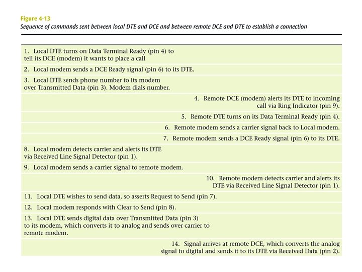
Procedural Specification • E. g. Asynchronous private line modem • When turned on and ready, modem (DCE) asserts DCE ready • When DTE ready to send data, it asserts Request to Send – Also inhibits receive mode in half duplex • Modem responds when ready by asserting Clear to send • DTE sends data • When data arrives, local modem asserts Receive Line Signal Detector and delivers data
Dial Up Operation (1)
Dial Up Operation (2)
Dial Up Operation (3)
Null Modem
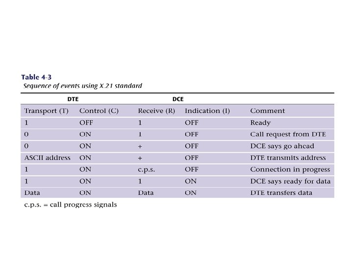
X. 21 Another interface standard that was designed to replace the aging RS-232. Currently popular in Europe and with ISDN connections. Each circuit in the X. 21 standard can contain many different signals. Since each circuit can transmit different signals, the combination of signals on the four circuits is much larger than if each circuit performed only a single function.
Review Questions • With async and sync transmissions, list all the ways you can resolve synchronization problems • Show 100 characters being sent using async transmission. How much overhead? • Show 100 characters being sent using sync transmission. How much overhead?
Review Questions • Describe the four components of an interface • What is the procedure to establish an EIA 232 F interface? • What sends a DCE ready signal? Where does it go?