Data and Computer Communications Tenth Edition by William

Data and Computer Communications Tenth Edition by William Stallings Data and Computer Communications, Tenth Edition by William Stallings, (c) Pearson Education, - 2013

CHAPTER 12 Ethernet

“Congratulations. I knew the record would stand until it was broken. ” - Yogi Berra

Traditional Ethernet Earliest was ALOHA • • Developed for packet radio networks Station may transmit a frame at any time If frame is determined invalid, it is ignored Maximum utilization of channel about 18% Next came slotted ALOHA • Organized slots equal to transmission time • Increased utilization to about 37%
 l l l Station listens to")
CSMA/CD Precursors Ø Carrier Sense Multiple Access (CSMA) l l l Station listens to determine if there is another transmission in progress If idle, station transmits Waits for acknowledgment If no acknowledgment, collision is assumed and station retransmits Utilization far exceeds ALOHA
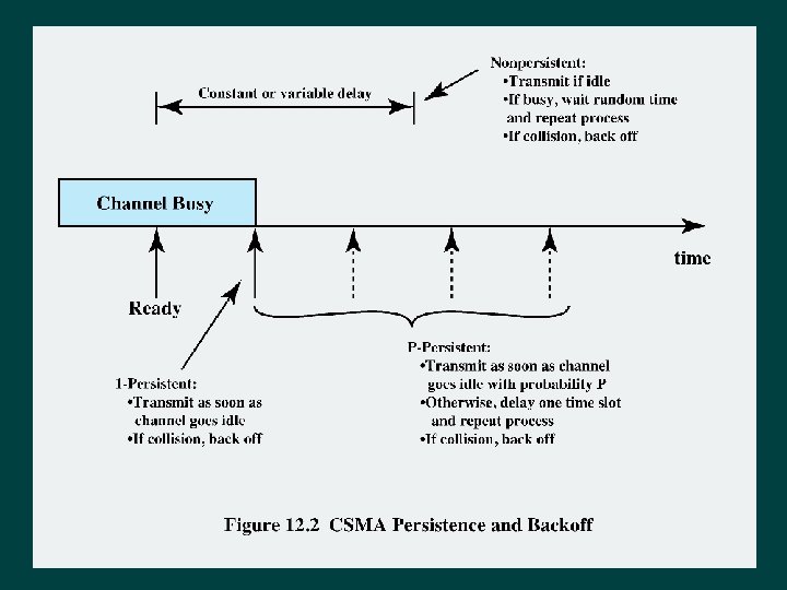

Nonpersistent CSMA If the medium is idle, transmit; otherwise, go to step 2 If the medium is busy, wait an amount of time drawn from a probability distribution and repeat step 1 Disadvantage: Capacity is wasted because the medium will generally remain idle following the end of a transmission even if there are one or more stations waiting to transmit

1 -Persistent CSMA Avoids idle channel time Ø Rules: Ø 1. If medium is idle, transmit 2. If medium is busy, listen until idle; then transmit immediately Stations are selfish Ø If two or more stations are waiting, a collision is guaranteed Ø

P-Persistent CSMA A compromise to try and reduce collisions and idle time Ø P-persistent CSMA rules: Ø 1. If medium is idle, transmit with probability p, and delay one time unit with probability (1–p) 2. If medium is busy, listen until idle and repeat step 1 3. If transmission is delayed one time unit, repeat step 1 Ø Issue of choosing effective value of p to avoid instability under heavy load

Value of p? Have n stations waiting to send Ø At end of transmission, expected number of stations is np Ø l If np>1 on average there will be a collision Repeated transmission attempts mean collisions are likely Ø Eventually all stations will be trying to send, causing continuous collisions, with throughput dropping to zero Ø To avoid catastrophe np<1 for expected peaks of n Ø l l If heavy load expected, p must be small Smaller p means stations wait longer

Description of CSMA/CD 3. 1. If the medium is idle, transmit; otherwise, go to step 2 2. If the medium is busy, continue to listen until the channel is idle, then transmit immediately If a collision is detected, transmit a brief jamming signal to assure that all stations know that there has been a collision and cease transmission 4. After transmitting the jamming signal, wait a random amount of time, referred to as the backoff, then attempt to transmit again

Frame should be long enough for CD

Which Persistence Algorithm? Ø IEEE 802. 3 uses 1 -persistent Ø Both nonpersistent and p-persistent have performance problems 1 -persistent seems more unstable than p-persistent • Because of greed of the stations • Wasted time due to collisions is short • With random backoff unlikely to collide on next attempt to send

Binary Exponential Backoff IEEE 802. 3 and Ethernet both use binary exponential backoff Ø A station will attempt to transmit repeatedly in the face of repeated collisions Ø l l l On first 10 attempts, mean random delay doubled Value then remains the same for 6 further attempts After 16 unsuccessful attempts, station gives up and reports error 1 -persistent algorithm with binary exponential backoff is efficient over wide range of loads Ø Backoff algorithm has last-in, first-out effect Ø

Collision Detection On baseband bus Collision produces higher signal voltage Collision detected if cable signal is greater than single station signal Signal is attenuated over distance Limit to 500 m (10 Base 5) or 200 m (10 Base 2) On twisted pair (star-topology) Activity on more than one port is collision Use special collision presence signal
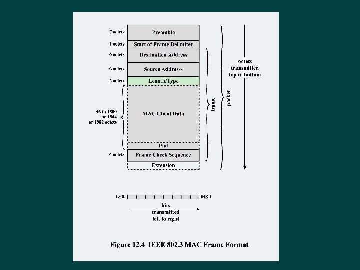

Table 12. 1 IEEE 802. 3 10 -Mbps Physical Layer Medium Alternatives

Table 12. 2 IEEE 802. 3 100 BASE-T Physical Layer Medium Alternatives

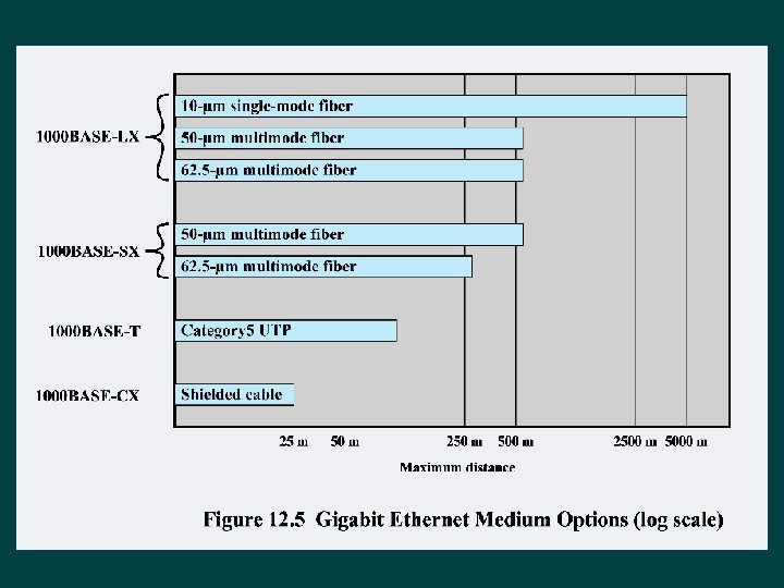
100 BASE-X Uses a unidirectional data rate 100 Mbps over single twisted pair or optical fiber link Ø Encodingscheme same as FDDI l 4 B/5 B-NRZI Ø Two physical medium specifications 100 BASE-TX Uses two pairs of twisted-pair cable STP and Category 5 UTP allowed 100 BASE-FX MTL-3 signaling scheme is used Uses two optical fiber cables Convert 4 B/5 B-NRZI code group into optical signals

100 BASE-T 4 Ø 100 -Mbps over lower-quality Cat 3 UTP l l l Ø Can not get 100 Mbps on single twisted pair l l Ø Takes advantage of large installed base Doesnot transmit continuous signal between packets Usefulin battery-powered applications So data stream split into three separate streams Four twisted pairs used Data transmitted and received using three pairs Two pairs configured for bidirectional transmission Use ternary signaling scheme (8 B 6 T)

Full Duplex Operation Traditional Ethernet half duplex Ø Using full-duplex, station can transmit and receive simultaneously Ø 100 -Mbps Ethernet in full-duplex mode, giving a theoretical transfer rate of 200 Mbps Ø Stations must have full-duplex adapter cards Ø And must use switching hub Ø l l l Each station constitutes separate collision domain CSMA/CD algorithm no longer needed 802. 3 MAC frame format used

Mixed Configurations Fast Ethernet supports mixture of existing 10 Mbps LANs and newer 100 -Mbps LANs Ø Supporting older and newer technologies Ø Stations attach to 10 -Mbps hubs using 10 BASE-T Hubs connected to switching hubs using 100 BASE-T High-capacity workstations and servers attach directly to 10/100 switches Switches connected to 100 -Mbps hubs use 100 -Mbps links 100 -Mbps hubs provide building backbone Connected to router providing connection to WAN

Gigabit Ethernet - Differences For shared medium hub operation Ø Carrier extension l At least 4096 bit-times long (512 for 10/100) Ø Frame bursting Ø Not needed if using a switched hub to provide dedicated media access

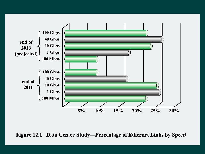
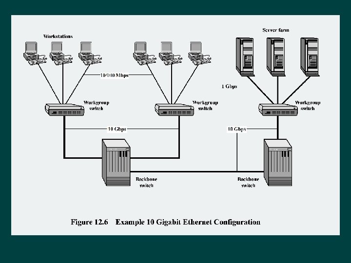
10 Gbps Ethernet Ø Growing interest in 10 Gbps Ethernet l l High-speed backbone use Future wider deployment Alternative to ATM and other WAN technologies Ø Uniform technology for LAN, MAN, or WAN Ø Advantages of 10 Gbps Ethernet Ø l l l No expensive, bandwidth-consuming conversion between Ethernet packets and ATM cells IP and Ethernet together offers Qo. S and traffic policing approach ATM Have a variety of standard optical interfaces

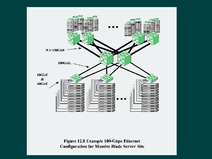
100 -Gbps Ethernet Ø Preferred technology for wired LAN Ø Preferred carrier for bridging wireless technologies into local Ethernet networks Ø Cost-effective, reliable and interoperable Ø Popularity of Ethernet technology: l l l Availability of cost-effective products Reliable and interoperable network products Variety of vendors

Multilane Distribution used to achieve the required data rates Ø Multilane distribution: l Switches implemented as multiple parallel channels Ø Virtual lanes: l • Separate physical wires l If a different number of lanes are actually in use, virtual lanes are distributed into physical lanes in the PMD sublayer Form of inverse multiplexing
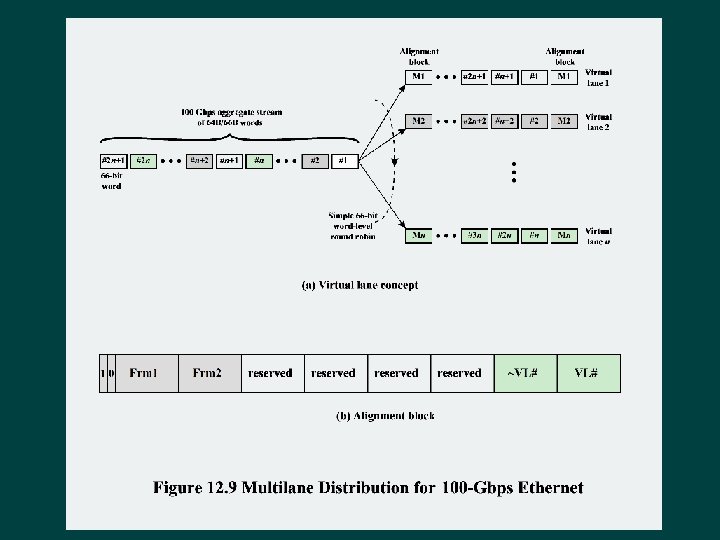
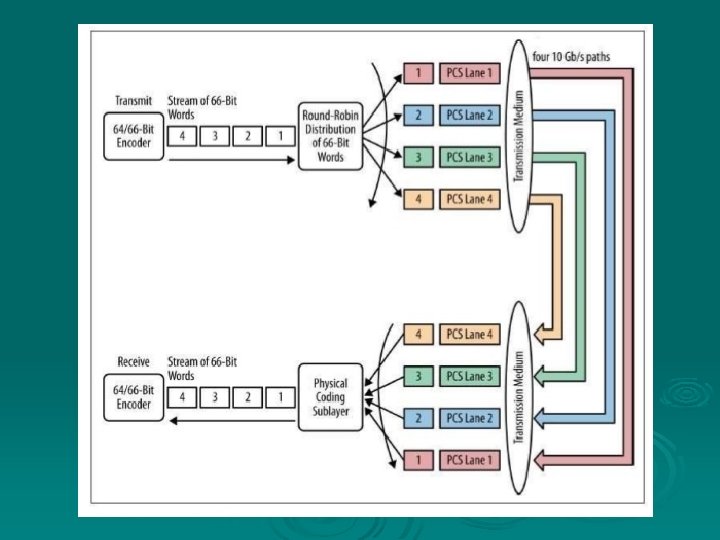

Table 12. 3 Media Options for 40 -Gbps and 100 -Gbps Ethernet Naming nomenclature: Copper: K = backplane; C = cable assembly Optical: S = short reach (100 m); L - long reach (10 km); E = extended long reach (40 km) Coding scheme: R = 64 B/66 B block coding Final number: number of lanes (copper wires or fiber wavelengths)
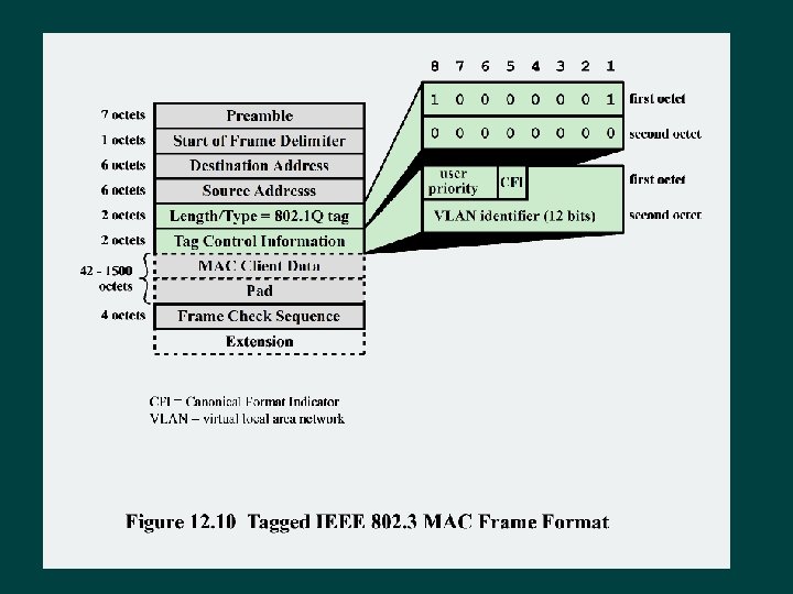

Trunk line VLAN Tag insertion C MA e Fram

Trunking traffic between switches Same VLAN

Summary Ø Traditional Ethernet l l Ø IEEE 802. 3 medium access control IEEE 802. 3 10 -Mbps specifications (Ethernet) IEEE 802. 1 Q VLAN standard Ø High-speed Ethernet l l IEEE 802. 3 100 -Mbps specifications (Fast Ethernet) Gigabit Ethernet 10 -Gbps Ethernet 100 -Gbps Ethernet
- Slides: 38