Data and Computer Communications Tenth Edition by William

Data and Computer Communications Tenth Edition by William Stallings Data and Computer Communications, Tenth Edition by William Stallings, (c) Pearson Education - 2013

CHAPTER 16 Advanced Data Communications Topics

“Life in the modern world is coming to depend more and more upon technical means of communication. Without such technical aids the modern city-state could not exist, for it is only by means of them that trade and business can proceed; that goods and services can be distributed where needed; that railways can run on schedule; that law and order are maintained; that education is possible. Communication renders true social life practicable, for communication means organization. ” —On Human Communication, Colin Cherry

Analog Data, Analog Signals Ø There are two principal reasons for analog modulation of analog signals: l l A higher frequency may be needed for effective transmission Modulation permits frequency -division multiplexing Principal techniques for modulation using analog data are: Amplitude modulation (AM) Frequency modulation (FM) Phase modulation (PM)
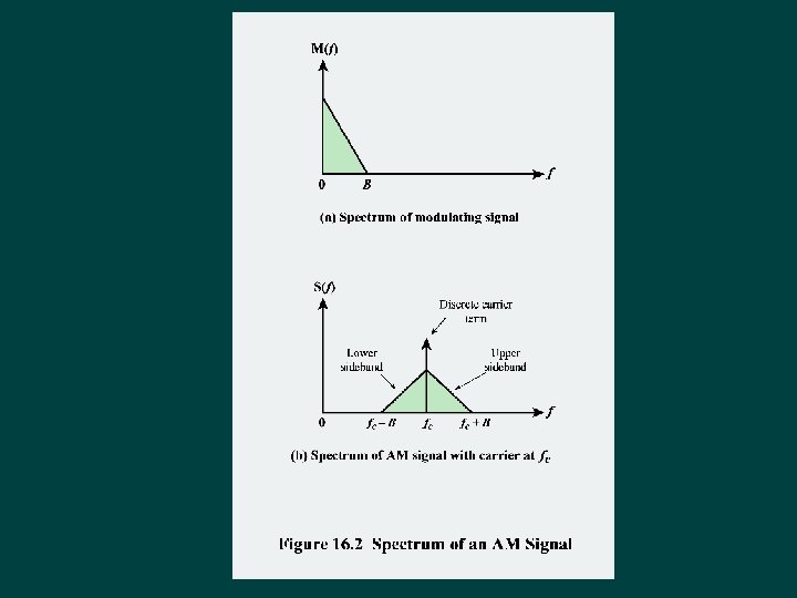
 and phase modulation (PM) Ø")
Angle Modulation Ø Special cases are frequency modulation (FM) and phase modulation (PM) Ø For phase modulation the phase is proportional to the modulating signal Ø For frequency modulation the derivative of the phase is proportional to the modulating signal

Cyclic Codes Ø Many of the error-correcting block codes that are in use are in this category l l Ø This class of codes can be easily encoded and decoded using linear feedback shift registers (LFSRs) Bose-Chaudhuri-Hocquenghem (BCH) and Reed-Solomon are examples LFSR implementation is the same as that of the CRC (cyclic redundancy check) error-detecting code l Key difference is that the CRC code takes an input of arbitrary length and produces a fixed-length CRC check code while a cyclic error-correcting code takes a fixedlength input and produces a fixed-length check code
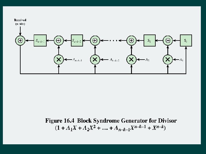

Decoding of a Cyclic Code Ø The following procedure is used: Process received bits to compute the syndrome code in exactly the same fashion as the encoder processes the data bits to produce the check If the syndrome bits are all zero, no error has been detected If the syndrome is nonzero, perform additional processing on the syndrome for error correction
 Cyclic Code")
Table 16. 1 A Single-Error-Correcting (7, 4) Cyclic Code

BCH Codes Ø Among the most powerful cyclic block codes Ø Widely used in wireless applications Ø Provide flexibility in the choice of parameters (block length, code rate) Ø For any positive pair of integers mand t, there is a binary (n, k) BCH code with the following parameters: l l l Block length: n = 2 m – 1 Number of check bits: n - k ≤ mt Minimum distance: dmin ≥ 2 t + 1

Table 16. 2 BCH Code Parameters

Table 16. 3 BCH Polynomial Generators
 Ø Widely used subclass of nonbinary BCH codes Ø Data are")
Reed-Solomon Codes (RS) Ø Widely used subclass of nonbinary BCH codes Ø Data are processed in chunks of mbits called symbols Ø An (n, k) RS code has the following parameters: l l l Symbol length: m bits per symbol Block length: n = 2 m - 1 symbols = m(2 m- 1) bits Data length: k symbols Size of check code: n - k = 2 t symbols = m(2 t) bits Minimum distance: dmin= 2 t + 1 symbols
 Ø Low-density parity-check code (LDPC) l")
Parity-Check Matrix Codes Ø Forward error correction (FEC) Ø Low-density parity-check code (LDPC) l l Exhibit performance in terms of bit error probability that is very close to the Shannon limit and can be efficiently implemented for high-speed use Used in: • • High-speed wireless specifications 802. 11 n and 802. 11 ac Wi-Fi Satellite digital television transmission 10 -Gbps Ethernet
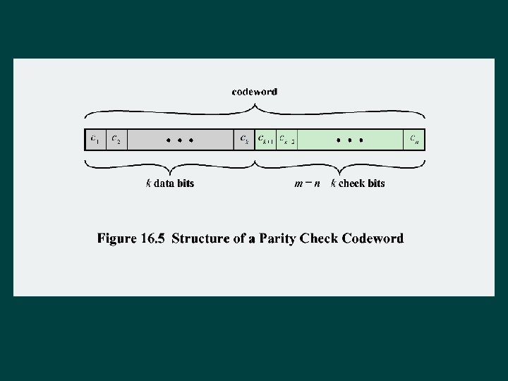

Parity-Check Code Ø For a parity-check code there are three functions to perform: Encoding • For a given set of k data bits, generate the corresponding n–bit codeword Error detection • For a given codeword, determine if there are one or more bits in error Error correction • If an error is detected, perform error correction
 Parity Check Code Defined by Equation (16. 15)")
Table 16. 4 (7, 4) Parity Check Code Defined by Equation (16. 15)

LDPC Codes Ø Ø Low-Density Parity-Check Codes Parity-check code with parity-check matrix H with the following properties: 1. 2. Ø • Each row of H contains wr 1 s • Each column of H contains wc 1 s 3. • The number of 1 s in common between any two columns is zero or one 4. • Both wr and wc are small compared to the codeword and the number of rows Because of property 4, H has a small density of 1 s l l The elements of H are almost all equal to 0 Hence the designation low density

Figure 16. 6 Examples of LDPC Parity-Check Matrices

Figure 16. 6 Examples of LDPC Parity-Check Matrices

Figure 16. 6 Examples of LDPC Parity-Check Matrices

Error Correction Ø Error detection of an LDPC code can be performed using the parity-check matrix l If Hc. Tyields a nonzero vector, then an error is detected Ø Tanner graph l Contains two kinds of nodes • Check nodes which correspond to rows of H • Bit nodes which correspond to columns of H and hence to the bits of the codeword
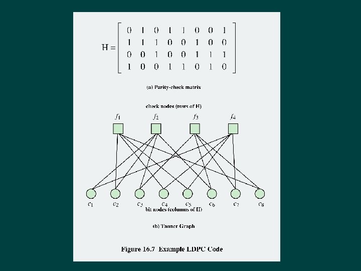

Table 16. 5 Example Error Correction Technique for LDPC of Figure 16. 7
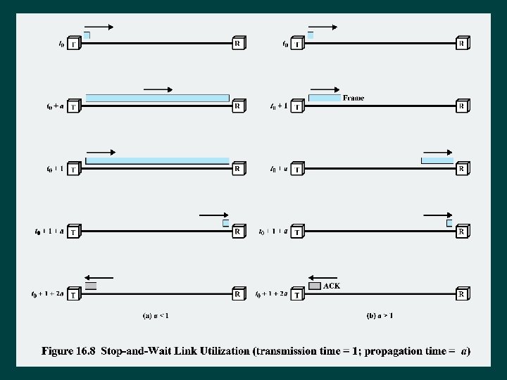
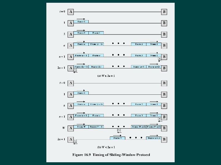
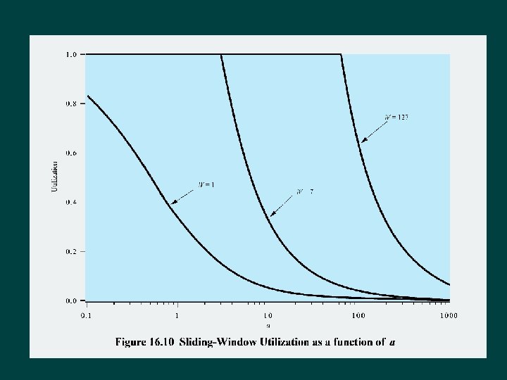
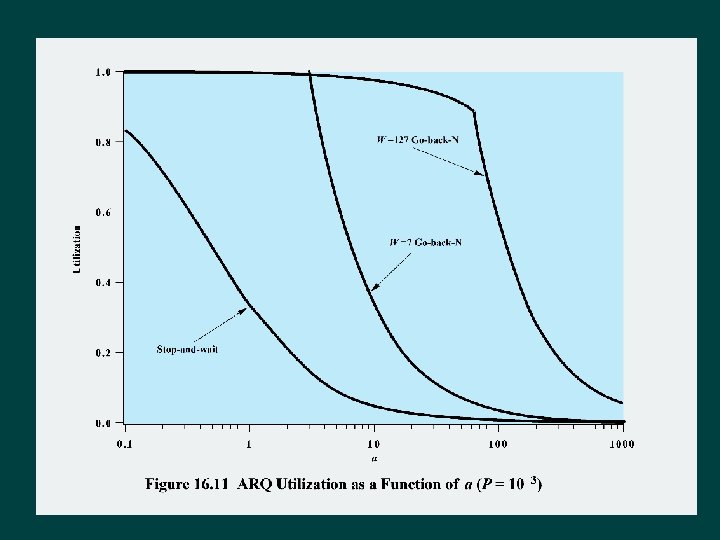

Summary Ø Analog data, analog signals l l Ø Amplitude modulation Angle modulation ARQ performance issues l l l Stop-and-wait flow control Error-free slidingwindow flow control ARQ Ø Forward errorcorrecting codes l l l Cyclic codes BCH codes Reed-Solomon codes Parity-check matrix codes Low-density paritycheck codes
- Slides: 30