Dasar Keteknikan Pengolahan Pangan Sudarminto Setyo Yuwono Apple


![example: • • • Length = [L], area = [L] 2, volume = [L]](https://slidetodoc.com/presentation_image_h/80e37dbebe597b4deb82afa8c18826a1/image-6.jpg "example: • • • Length = [L], area = [L] 2, volume = [L]")
 is defined in terms of the wavelength of light;")


, sebanyak 1000 kg/jam larutan mengandung")


 x (0. 05)2 = 1. 96 x 10")


 = t")


")
 streamline flow, Hagen-Poiseuille equation 0 < (Re) <")
 0. 001 -")

 (k. J")


 tube")


 Riveted steel")


 20 22 24 26 28 30 40 50 60 70 80")

 is the amount of heat that accompanies")
")
 for")


 20 22 24 26 28 30 40 50 60 70 80")

- Slides: 90
Dasar Keteknikan Pengolahan Pangan Sudarminto Setyo Yuwono
Apple Cooling qfrig
INTRODUCTION • The study of process engineering is an attempt to combine all forms of physical processing into a small number of basic operations, which are called unit operations • Food processes may seem bewildering in their diversity, but careful analysis will show that these complicated and differing processes can be broken down into a small number of unit operations • Important unit operations in the food industry are fluid flow, heat transfer, drying, evaporation, contact equilibrium processes (which include distillation, extraction, gas absorption, crystallization, and membrane processes), mechanical separations (which include filtration, centrifugation, sedimentation and sieving), size reduction and mixing.
DIMENSIONS AND UNITS • All engineering deals with definite and measured quantities, and so depends on the making of measurements • To make a measurement is to compare the unknown with the known • record of a measurement consists of three parts: the dimension of the quantity, the unit which represents a known or standard quantity and a number which is the ratio of the measured quantity to the standard quantity
Dimensions • These dimensions are length, mass, time and temperature. • For convenience in engineering calculations, force is added as another dimension • Dimensions are represented as symbols by: length [L], mass [M], time [t], temperature [T] and force [F]. •
example: • • • Length = [L], area = [L] 2, volume = [L] 3. Velocity = length travelled per unit time=[L]/[t] Pressure = force per unit area=[F]/[L] 2 Energy = force times length=[F] x [L]. Power = energy per unit time=[F] x [L]/[t] h=[F] x [L]/[L]2 [t] [T] =[F] [L] -1 [t] -1 [T] -1
Units • the metre (m) is defined in terms of the wavelength of light; • the standard kilogram (kg) is the mass of a standard lump of platinum -iridium; • the second (s) is the time taken for light of a given wavelength to vibrate a given number of times; • the degree Celsius (°C) is a one-hundredth part of the temperature interval between the freezing point and the boiling point of water at standard pressure; • the unit of force, the newton (N), is that force which will give an acceleration of 1 m sec-2 to a mass of 1 kg; • the energy unit, the newton metre is called the joule (J), • the power unit, 1 J s-1, is called the watt (W).
Dimensionless Ratios • It is often easier to visualize quantities if they are expressed in ratio form and ratios have the great advantage of being dimensionless • For example, specific gravity is a simple way to express the relative masses or weights of equal volumes of various materials. The specific gravity is defined as the ratio of the weight of a volume of the substance to the weight of an equal volume of water SG = weight of a volume of the substance/ weight of an equal volume of water. Dimensionally, SG=[F]/ [L]-3 divided by[F]/ [L]-3 = 1 it gives an immediate sense of proportion This sense of proportion is very important to food technologists as they are constantly making approximate mental calculations for which they must be able to maintain correct proportions Another advantage of a dimensionless ratio is that it does not depend upon the units of measurement used, provided the units are consistent for each dimension Dimensionless ratios are employed frequently in the study of fluid flow and heat flow. These dimensionless ratios are then called dimensionless numbers and are often called after a prominent person who was associated with them, for example Reynolds number, Prandtl number, and Nusselt number • • •
Neraca Massa • Tahapan perhitungan: – Gambar diagram – Tulis reaksi kimia jika ada – Tulis dasar-dasar perhitungan – Hitung neraca massanya
Mass Balance • Proses produksi soda api (Na. OH), sebanyak 1000 kg/jam larutan mengandung 7, 5% Na. OH di pekatkan pada evaporator yang pertama sehingga kadarnya menjadi 20%. Larutan ini lalu dipekatkan pada evaporator yang kedua yang menghasilkan pekatan berkadar 60% Na. OH. Hitung Na. OH yang dihasilkan.
Neraca massa jika terjadi reaksi kimia • Beberapa proses pengolahan kemungkinan terjadi reaksi kimia – Fermentasi – Pembakaran • Dasar perhitungan bukan dari massa tetapi dari perubahan mol • Setelah itu baru dikonversikan ke massa
contoh • Bahan bakar mengandung 5 %mol H 2, 30 %mol CO, 5 %mol CO 2, 1 %mol O 2, dan 59 %mol N 2. Dibakar dengan media udara. Untuk 100 kg mol bahan bakar hitung mol gas buang dan kamponennya, jika : • A. Pembakaran sempurna, udara pas • B. Pembakaran 90% sempurna • C. Udara berlebih 20%, pembakaran sempurna 80%
contoh • Larutan Na. OH diproduksi dengan cara menambahkan larutan Na 2 CO 3 10% ke dalam aliran bubur Ca(OH) 2 25%. Bagaimana komposisi bubur akhir jika reaksi 90% sempurna dan 100% sempurna. Gunakan dasar 100 kg aliran bubur Ca(OH)2 • Na 2 CO 3 + Ca(OH) 2 => 2 Na. OH + Ca. CO 3 • Ca(OH) 2= 74, 1; Na 2 CO 3 = 106
Recycle • Pada suatu proses produksi sodium sitrat, 1000 kg/jam larutan sodium sitrat berkadar 20% dipekatkan di suatu evaporator bersuhu 353 K sehingga diperoleh kadar 50%. Larutan lalu dimasukkan ke kristalizer yang bersuhu 303 K sehingga diperoleh kristal Na sitrat berkadar 95%. Larutan jenuh yang mengandung 30% Na sitrat lalu direcycle ke evaporator. Hitung berapa laju aliran recycle dan produk yang dihasilkan.
Harap dikerjakan • Pada industri gula, larutan gula 1000 kg/jam berkadar 30% dipekatkan hingga berkadar 60%. Larutan tersebut lalu dimasukkan ke kristalizer sehingga diperoleh kristal gula berkadar air 5%. Larutan jenuh berkadar gula 40% selanjutnya direcycle ke evaporator lagi. Hitung jumlah larutan yang direcycle dan gula yang dihasilkan.
FLUID FLOW THEORY • Many raw materials for foods and many finished foods are in the form of fluids. • Thin liquids - milk, water, fruit juices, Thick liquids - syrups, honey, oil, jam, Gases - air, nitrogen, carbon dioxide, Fluidized solids - grains, flour, peas. • The study of fluids can be divided into: – the study of fluids at rest - fluid statics, and – the study of fluids in motion - fluid dynamics.
FLUID STATICS • very important property : the fluid pressure • Pressure is force exerted on an area • force is equal to the mass of the material multiplied by the acceleration due to gravity. • mass of a fluid can be calculated by multiplying its volume by its density • F = mg = Vρg • F is force (Newton) or kg m s-2, m is the mass, g the acceleration due to gravity, V the volume and ρ the density.
The force per unit area in a fluid is called the fluid pressure. It is exerted equally in all directions. • F = APs + ZρAg • Ps is the pressure above the surface of the fluid (e. g. it might be atmospheric pressure • total pressure P = F/A = Ps + Zρg • the atmospheric pressure represents a datum P = Zρg
EXAMPLE. Total pressure in a tank of peanut oil • Calculate the greatest pressure in a spherical tank, of 2 m diameter, filled with peanut oil of specific gravity 0. 92, if the pressure measured at the highest point in the tank is 70 k. Pa.
• Density of water = 1000 kg m-3 Density of oil = 0. 92 x 1000 kg m-3 = 920 kg m-3 Z =greatest depth = 2 m and g = 9. 81 m s-2 Now P = Zρg = 2 x 920 x 9. 81 kg m-1 s-2 = 18, 050 Pa = 18. 1 k. Pa. • To this must be added the pressure at the surface of 70 k. Pa. • Total pressure = 70 + 18. 1 = 88. 1 k. Pa. • the pressure depends upon the pressure at the top of the tank, the depth of the liquid
Expressing the pressure • absolute pressures • gauge pressures • head
EXAMPLE. Head of Water • Calculate the head of water equivalent and mercury to standard atmospheric pressure of 100 k. Pa. • Density of water = 1000 kg m-3, Density of mercury = 13, 600 kg m-3 g = 9. 81 m s-2 and pressure = 100 k. Pa = 100 x 103 Pa = 100 x 103 kg m-1 s-2. Water Z = P/ ρ g = (100 x 103)/ (1000 x 9. 81) = 10. 2 m Mercury Z = (100 x 103)/ (13, 600 x 9. 81) = 0. 75 m
FLUID DYNAMICS • In most processes fluids have to be moved • Problems on the flow of fluids are solved by applying the principles of conservation of mass and energy • The motion of fluids can be described by writing appropriate mass and energy balances and these are the bases for the design of fluid handling equipment.
Mass Balance • ρ1 A 1 v 1 = ρ2 A 2 v 2 • incompressible ρ1 = ρ2 so in this case • A 1 v 1 = A 2 v 2 (continuity equation) • area of the pipe at section 1 is A 1 , the velocity at this section, v 1 and the fluid density ρ1 , and if the corresponding values at section 2 are A 2, v 2, ρ2
EXAMPLE. Velocities of flow • Whole milk is flowing into a centrifuge through a full 5 cm diameter pipe at a velocity of 0. 22 m s-1, and in the centrifuge it is separated into cream of specific gravity 1. 01 and skim milk of specific gravity 1. 04. Calculate the velocities of flow of milk and of the cream if they are discharged through 2 cm diameter pipes. The specific gravity of whole milk of 1. 035.
Solving • ρ1 A 1 v 1 = ρ2 A 2 v 2 + ρ3 A 3 v 3 • where suffixes 1, 2, 3 denote respectively raw milk, skim milk and cream. • since the total leaving volumes equal the total entering volume • A 1 v 1 = A 2 v 2 + A 3 v 3 • v 2 = (A 1 v 1 - A 3 v 3 )/A 2 • ρ1 A 1 v 1 = ρ2 A 2(A 1 v 1 – A 3 v 3)/A 2 + ρ3 A 3 v 3 • ρ1 A 1 v 1 = ρ2 A 1 v 1 - ρ2 A 3 v 3 + ρ3 A 3 v 3 • A 1 v 1(ρ1 - ρ2 ) = A 3 v 3(ρ3 - ρ2 )
• A 1 = (π/4) x (0. 05)2 = 1. 96 x 10 -3 m 2 • A 2 = A 3 = (π/4) x (0. 02)2 = 3. 14 x 10 -4 m 2 v 1 = 0. 22 m s-1 ρ1 = 1. 035, ρ2 = 1. 04, ρ3 = 1. 01 • A 1 v 1(ρ1 - ρ2 ) = A 3 v 3(ρ3 - ρ2 ) • -1. 96 x 10 -3 x 0. 22 (0. 005) = -3. 14 x 10 -4 x v 3 x (0. 03) v 3 = 0. 23 m s-1 • v 2 = (A 1 v 1 - A 3 v 3 )/A 2 • v 2 = [(1. 96 x 10 -3 x 0. 22) - (3. 14 x 10 -4 x 0. 23)] / 3. 14 x 10 -4 = 1. 1 m s-1
Energy Balance • Referring Fig. before we shall consider the changes in the total energy of unit mass of fluid, one kilogram, between Section 1 and Section 2. • Firstly, there are the changes in the intrinsic energy of the fluid itself which include changes in: (1) Potential energy = Ep = Zg (J) (2) Kinetic energy = Ek = v 2/2 (J) (3) Pressure energy = Er = P/ρ (J) • Secondly, there may be energy interchange with the surroundings including: (4) Energy lost to the surroundings due to friction = Eƒ (J). (5) Mechanical energy added by pumps = Ec (J). (6) Heat energy in heating or cooling the fluid • In the analysis of the energy balance, it must be remembered that energies are normally measured from a datum or reference level. • Ep 1 + Ek 1 + Er 1 = Ep 2 + Ek 2 + Er 2 + Ef - Ec. • Z 1 g + v 12/2 + P 1/ρ1 = Z 2 g + v 22/2 + P 2/ρ2 + Ef - Ec. • Zg + v 2/2 + P/ρ = k Persamaan Bernouilli
Water flows at the rate of 0. 4 m 3 min-1 in a 7. 5 cm diameter pipe at a pressure of 70 k. Pa. If the pipe reduces to 5 cm diameter calculate the new pressure in the pipe. Density of water is 1000 kg m-3. • • • Flow rate of water = 0. 4 m 3 min-1 = 0. 4/60 m 3 s-1. Area of 7. 5 cm diameter pipe = (π/4)D 2 = (π /4)(0. 075)2 = 4. 42 x 10 -3 m 2. So velocity of flow in 7. 5 cm diameter pipe, v 1 = (0. 4/60)/(4. 42 x 10 -3) = 1. 51 m s-1 Area of 5 cm diameter pipe = (π/4)(0. 05)2 = 1. 96 x 10 -3 m 2 and so velocity of flow in 5 cm diameter pipe, v 2 = (0. 4/60)/(1. 96 x 10 -3) = 3. 4 m s-1 Now Z 1 g + v 12/2 + P 1 /ρ1 = Z 2 g + v 22/2 + P 2 / ρ2 and so 0 + (1. 51)2/2 + 70 x 103/1000 = 0 + (3. 4)2/2 + P 2/1000 0 + 1. 1 + 70 = 0 + 5. 8 + P 2/1000 P 2/1000 = (71. 1 - 5. 8) = 65. 3 P 2 = 65. 3 k Pa.
Water is raised from a reservoir up 35 m to a storage tank through a 7. 5 cm diameter pipe. If it is required to raise 1. 6 cubic metres of water per minute, calculate the horsepower input to a pump assuming that the pump is 100% efficient and that there is no friction loss in the pipe. 1 Horsepower = 0. 746 k. W. • • • Volume of flow, V = 1. 6 m 3 min-1 = 1. 6/60 m 3 s-1 = 2. 7 x 10 -2 m 3 s-1 Area of pipe, A = (π/4) x (0. 075)2 = 4. 42 x 10 -3 m 2, Velocity in pipe, v = 2. 7 x 10 -2/(4. 42 x 10 -3) = 6 m s-1, And so applying eqn Z 1 g + v 12/2 + P 1/ρ1 = Z 2 g + v 22/2 + P 2/ρ2 + Ef - Ec. Ec = Zg + v 2/2 Ec = 35 x 9. 81 + 62/2 = 343. 4 + 18 = 361. 4 J Therefore total power required = Ec x mass rate of flow = Ec. Vρ = 361. 4 x 2. 7 x 10 -2 x 1000 J s-1 = 9758 J s-1 and, since 1 h. p. = 7. 46 x 102 J s-1, required power = 13 h. p.
VISCOSITY • Viscosity is that property of a fluid that gives rise to forces that resist the relative movement of adjacent layers in the fluid. • Viscous forces are of the same character as shear forces in solids and they arise from forces that exist between the molecules. • If two parallel plane elements in a fluid are moving relative to one another, it is found that a steady force must be applied to maintain a constant relative speed. This force is called the viscous drag because it arises from the action of viscous forces.
If the plane elements are at a distance Z apart, and if their relative velocity is v, then the force F required to maintain the motion has been found, experimentally, to be proportional to v and inversely proportional to Z for many fluids. The coefficient of proportionality is called the viscosity of the fluid, and it is denoted by the symbol µ (mu). From the definition of viscosity we can write F/A = µ v/Z
Unit of Viscosity • • • N s m-2 = Pascal second, Pa s, The older units, the poise and its sub-unit the centipoise, 1000 centipoises = 1 N s m-2, or 1 Pa s. the viscosity of water at room temperature 1 x 10 -3 N s m-2 acetone, 0. 3 x 10 -3 N s m-2; tomato pulp, 3 x 10 -3; olive oil, 100 x 10 -3; molasses 7000 N s m-3. Viscosity is very dependent on temperature decreasing sharply as the temperature rises. For example, the viscosity of golden syrup is about 100 N s m-3 at 16°C, 40 at 22°C and 20 at 25°C.
Newtonian and Non-Newtonian Fluids • F/A = µ v /Z = µ(dv/dz) = t • t = k(dv/dz)n power-law equation • Newtonian fluids (n = 1, k = µ ) • Non-Newtonian fluids (n ≠ 1) • (1) Those in which n < 1. The viscosity is apparently high under low shear forces decreasing as the shear force increases. Pseudoplastic (tomato puree) • (2) Those in which n > 1. With a low apparent viscosity under low shear stresses, they become more viscous as the shear rate rises. Dilatancy (gritty slurries such as crystallized sugar solutions). • Bingham fluids have to exceed a particular shear stress level (a yield stress) before they start to move. • Food : Non-Newtonian
STREAMLINE AND TURBULENT FLOW • STREAMLINE, flow is calm, in slow the pattern and smooth • TURBULENT, the flow is more rapid, eddies develop and swirl in all directions and at all angles to the general line of flow. rv 2 D/mv = Dvr/m =Reynolds number (Re), dimensionless • D is the diameter of the pipe • For (Re) < 2100 streamline flow, For 2100 < (Re) < 4000 transition, For (Re) > 4000 turbulent flow.
EXAMPLE. Flow of milk in a pipe Milk is flowing at 0. 12 m 3 min-1 in a 2. 5 -cm diameter pipe. If the temperature of the milk is 21°C, is the flow turbulent or streamline? • Viscosity of milk at 21°C = 2. 1 c. P = 2. 10 x 10 -3 N s m-2 Density of milk at 21°C = 1029 kg m-3. Diameter of pipe = 0. 025 m. Cross-sectional area of pipe = (p/4)D 2 = p/4 x (0. 025)2 = 4. 9 x 10 -4 m 2 Rate of flow = 0. 12 m 3 min-1 = (0. 12/60) m 3 s-1 = 2 x 10 m 3 s-1 • So velocity of flow = (2 x 10 -3)/(4. 9 x 10 -4) = 4. 1 m s-1, and so (Re) = (Dvr/m) = 0. 025 x 4. 1 x 1029/(2. 1 x 10 -3) = 50, 230 and this is greater than 4000 so that the flow is turbulent.
ENERGY LOSSES IN FLOW • • Friction in Pipes Energy Losses in Bends and Fittings Pressure Drop through Equipment Equivalent Lengths of Pipe
Friction in Pipes • Eƒ : the energy loss due to friction in the pipe. • Eƒ : proportional to the velocity pressure of the fluid and to a factor related to the smoothness of the surface over which the fluid is flowing. • F/A = f rv 2/2 • F is the friction force, A is the area over which the friction force acts, r is the density of the fluid, v is the velocity of the fluid, and f is a coefficient called the friction factor (depends upon the Reynolds number for the flow, and upon the roughness of the pipe). • § • • P 1 - P 2 = (4 frv 2/2)(L 1 - L 2)/D DPf = (4 frv 2/2) x (L/D) (Fanning-D'Arcy equation) Eƒ = DPf/r = (2 fv 2)(L/D) L = L 1 - L 2 = length of pipe in which the pressure drop, DPf = P 1 - P 2 is the frictional pressure drop, and Eƒ is the frictional loss of energy.
Friction factors in pipe (Moody graph)
predicted f • f = 16/(Re) streamline flow, Hagen-Poiseuille equation 0 < (Re) < 2100 • ƒ = 0. 316 ( Re)-0. 25/4 ( Blasius equation for smooth pipes in the range 3000 < (Re) < 100, 000) • roughness ratio = Roughness factor (e)/pipe diameter (turbulent region) •
ROUGHNESS FACTORS FOR PIPES Material Riveted steel Roughness factor Material (e) 0. 001 - 0. 01 Concrete 0. 0003 - 0. 003 Wood staves 0. 0002 - 0. 003 Cast iron 0. 0003 Galvanized iron Asphalted cast iron Commercial steel Roughness factor (e) 0. 0002 0. 001 0. 00005 Drawn tubing Smooth
EXAMPLE Pressure drop in a pipe Calculate the pressure drop along 170 m of 5 cm diameter horizontal steel pipe through which olive oil at 20°C is flowing at the rate of 0. 1 m 3 min-1 • • • Diameter of pipe = 0. 05 m, Area of cross-section A = (π/4)D 2 = π /4 x (0. 05)2 = 1. 96 x 10 -3 m 2 From Appendix 4, Viscosity of olive oil at 20°C = 84 x 10 -3 Ns m-2 and density = 910 kg m-3, and velocity = (0. 1 x 1/60)/(1. 96 x 10 -3) = 0. 85 m s-1, Now (Re) = (Dvρ/µ) = [(0. 05 x 0. 85 x 910)/(84 x 10 -3)] = 460 so that the flow is streamline, and from Fig. moody, for (Re) = 460 f = 0. 03. Alternatively for streamline flow from f = 16/(Re) = 16/460 = 0. 03 as before. And so the pressure drop in 170 m, DPf = (4 frv 2/2) x (L/D) = [4 x 0. 03 x 910 x (0. 85)2 x 1/2] x [170 x 1/0. 05] = 1. 34 x 105 Pa = 134 k. Pa.
Thermal conductivity Specific heat Density Viscosity Temperature (J m-1 s-1 °C-1) (k. J kg-1 °C-1) (kg m-3) (N s m-2) (°C) 0. 57 4. 21 1000 1. 87 x 10 -3 0 4. 21 987 0. 56 x 10 -3 50 Water 0. 68 4. 18 958 0. 28 x 10 -3 100 Sucrose 20% soln. 0. 54 3. 8 1070 1. 92 x 10 -3 20 0. 59 x 10 -3 80 60% soln. 6. 2 x 10 -3 20 5. 4 x 10 -3 80 Sodium chloride 22% soln. 0. 54 3. 4 1240 2. 7 x 10 -3 2 Olive oil 0. 17 2. 0 910 84 x 10 -3 20 Rape-seed oil 900 118 x 10 -3 20 Soya-bean oil 910 40 x 10 -3 30 Tallow 900 18 x 10 -3 65 1030 2. 12 x 10 -3 20 25 Milk (whole) 0. 56 3. 9 Milk (skim) 1040 1. 4 x 10 -3 Cream 20% fat 1010 6. 2 x 10 -3 3 30% fat 1000 13, 8 x 10 -3 3
Energy Losses in Bends and Fittings • energy losses due to altering the direction of flow, fittings of varying cross-section • This energy is dissipated in eddies and additional turbulence and finally lost in the form of heat. • Eƒ = kv 2/2 Losses in fittings • Ef = (v 1 - v 2)2/2 • Ef = kv 22/2 Losses in sudden enlargements Losses in sudden contraction
FRICTION LOSS FACTORS IN FITTINGS k Valves, fully open: LOSS FACTORS IN CONTRACTIONS gate 0. 13 globe 6. 0 angle 3. 0 90° standard 0. 74 D 2/D 1 0. 3 0. 5 0. 7 0. 9 medium sweep 0. 5 long radius 0. 25 k 0. 36 0. 31 0. 22 0. 11 0. 02 square 1. 5 Elbows: Tee, used as elbow 1. 5 Tee, straight through 0. 5 Entrance, large tank to pipe: sharp 0. 5 rounded 0. 05
FLUID-FLOW APPLICATIONS • • Two practical aspects of fluid flow in food technology : measurement in fluids: pressures and flow rates, and production of fluid flow by means of pumps and fans. Pumps and fans are very similar in principle and usually have a centrifugal or rotating action • a gas : moved by a fan, • a liquid: moved by a pump.
MEASUREMENT OF PRESSURE IN A FLUID • Method : – Piezometer ("pressure measuring") tube – U-tube – Pitot-static tube – Bourdon-tube • P = Z 1 r 1 g
EXAMPLE. Pressure in a vacuum evaporator The pressure in a vacuum evaporator was measured by using a U-tube containing mercury. It was found to be less than atmospheric pressure by 25 cm of mercury. Calculate the extent by which the pressure in the evaporator is below atmospheric pressure (i. e. the vacuum in the evaporator) in k. Pa, and also the absolute pressure in the evaporator. The atmospheric pressure is 75. 4 cm of mercury and the specific gravity of mercury is 13. 6, and the density of water is 1000 kg m-3. • We have P = Zrg = 25 x 10 -2 x 13. 6 x 1000 x 9. 81 = 33. 4 k. Pa • Therefore the pressure in the evaporator is 33. 4 k. Pa below atmospheric pressure and this is the vacuum in the evaporator. • For atmospheric pressure: • P = Zrg • P = 75. 4 x 10 -2 x 13. 6 x 1000 x 9. 81 = 100. 6 k. Pa Therefore the absolute pressure in the evaporator = 100. 6 - 33. 4 = 67. 2 k. Pa
MEASUREMENT OF VELOCITY IN A FLUID • • • Pitot tube and manometer : Z 1 g + v 12/2 + P 1/r 1 = Z 2 g + v 22/2 + P 2/r 1 Z 2 = Z + Z' Z' be the height of the upper liquid surface in the pipe above the datum, Z be the additional height of the fluid level in the tube above the upper liquid surface in the pipe; Z' may be neglected if P 1 is measured at the upper surface of the liquid in the pipe, or if Z' is small compared with Z v 2 = 0 as there is no flow in the tube P 2 = 0 if atmospheric pressure is taken as datum and if the top of the tube is open to the atmosphere Z 1 = 0 because the datum level is at the mouth of the tube. v 12/2 g + P 1/r 1 = (Z + Z')g » Z. Pitot-static tube Z = v 2/2 g
EXAMPLE. Velocity of air in a duct Air at 0°C is flowing through a duct in a chilling system. A Pitot-static tube is inserted into the flow line and the differential pressure head, measured in a micromanometer, is 0. 8 mm of water. Calculate the velocity of the air in the duct. The density of air at 0°C is 1. 3 kg m-3. • Z = v 12/2 g • r 1 Z 1 = r 2 Z 2. • Now 0. 8 mm water = 0. 8 x 10 -3 x = 0. 62 m of air • v 12 = 2 Zg = 2 x 0. 62 x 9. 81 = 12. 16 m 2 s-2 • Therefore v 1 = 3. 5 m s-1 1000 1. 3
Venturi and orifice meters • v 12/2 + P 1/r 1 = v 22/2+ P 2/r 2 (Bernouilli's equation) • A 1 v 1 = A 2 v 2 · r 1 = r 2 = r · v 12/2 + P 1/r = (v 1 A 1/A 2)2/2 + P 2/r (mass balance, eqn) v 12 = [2(P 2 -P 1)/r] x A 22/(A 22 -A 12) · (P 2 -P 1)/r = g. Zrm /r · Z = (P 2 -P 1)/rm g · v 1 = C √[2(P 2 -P 1 )/r]x A 22/(A 22 -A 12 ) · In a properly designed Venturi meter, C lies between 0. 95 and 1. 0.
Pompa dan Fan • mechanical energy from some other source is converted into pressure or velocity energy in a fluid. • The food technologist is not generally much concerned with design details of pumps, but should know what classes of pump are used and something about their characteristics. • The efficiency of a pump is the ratio of the energy supplied by the motor to the increase in velocity and pressure energy given to the fluid.
Jenis Pompa • Positive Displacement Pumps • the fluid is drawn into the pump and is then forced through the outlet • Positive displacement pumps can develop highpressure heads but they cannot tolerate throttling or blockages in the discharge.
Jet Pumps • a high-velocity jet is produced in a Venturi nozzle, converting the energy of the fluid into velocity energy. • This produces a low-pressure area causing the surrounding fluid to be drawn into the throat • Jet pumps are used for difficult materials that cannot be satisfactorily handled in a mechanical pump. • They are also used as vacuum pumps. • Jet pumps have relatively low efficiencies but they have no moving parts and therefore have a low initial cost.
Air-lift Pumps • • • air or gas can be used to impart energy to the liquid The air or gas can be either provided from external sources or produced by boiling within the liquid. Examples of the air-lift principle are: Air introduced into the fluid as shown in Fig. 4. 3(e) to pump water from an artesian well. Air introduced above a liquid in a pressure vessel and the pressure used to discharge the liquid. Vapours produced in the column of a climbing film evaporator. In the case of powdered solids, air blown up through a bed of powder to convey it in a "fluidized" form. A special case of this is in the evaporator, where boiling of the liquid generates the gas (usually steam) and it is used to promote circulation. Air or gas can be used directly to provide pressure to blow a liquid from a container out to a region of lower pressure. Air-lift pumps and air blowing are inefficient, but they are convenient for materials which will not pass easily through the ports, valves and passages of other types of pumps.
Propeller Pumps and Fan • Propellers can be used to impart energy to fluids • They are used extensively to mix the contents of tanks and in pipelines to mix and convey the fluid. • Propeller fans are common and have high efficiencies. • They can only be used for low heads, in the case of fans only a few centimetres or so of water
Centrifugal Pumps and Fans • The centrifugal pump converts rotational energy into velocity and pressure energy • The fluid to be pumped is taken in at the centre of a bladed rotor and it then passes out along the spinning rotor, acquiring energy of rotation. This rotational energy is then converted into velocity and pressure energy at the periphery of the rotor. • Centrifugal fans work on the same principles. These machines are very extensively used and centrifugal pumps can develop moderate heads of up to 20 m of water. They can deliver very large quantities of fluids with high efficiency.
Gambar jenis-jenis pompa
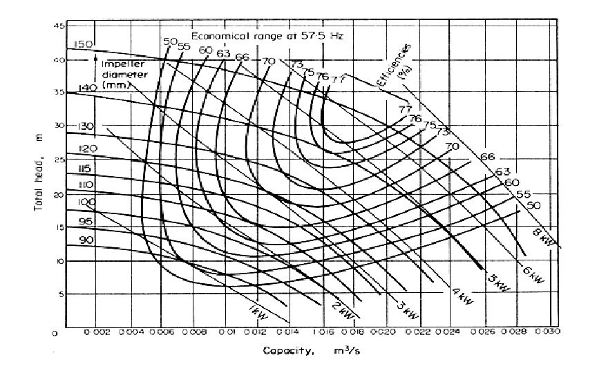
• EXAMPLE Centrifugal pump for raising water Water for a processing plant is required to be stored in a reservoir to supply sufficient working head for washers. It is believed that a constant supply of 1. 2 m 3 min-1 pumped to the reservoir, which is 22 m above the water intake, would be sufficient. The length of the pipe is about 120 m and there is available galvanized iron piping 15 cm diameter. The line would need to include eight right-angle bends. There is available a range of centrifugal pumps whose characteristics are shown in Fig. 4. 4. Would one of these pumps be sufficient for the duty and what size of electric drive motor would be required?
Reynold number • Assume properties of water at 20°C are density 998 kg m-3, and viscosity 0. 001 N s m-2 • Cross-sectional area of pipe A = (π/4)D 2 = π /4 x (0. 15)2 = 0. 0177 m-2 Volume of flow V = 1. 2 m 3 min-1 = 1. 2/60 m 3 s-1 = 0. 02 m 3 s-1. • Velocity in the pipe = V/A = (0. 02)/(0. 0177) = 1. 13 ms-1 • Now (Re) = Dvρ/µ • = (0. 15 x 1. 13 x 998)/0. 001 = 1. 7 x 10 5 so the flow is clearly turbulent.
friction loss of energy From Table 3. 1, the roughness factor ε is 0. 0002 for galvanized iron and so roughness ratio ε /D = 0. 0002/0. 15 = 0. 001 So from Fig. 3. 8, ƒ = 0. 0053 Therefore the friction loss of energy = (4ƒv 2/2) x (L/D) = [4ƒv 2 L/2 D] = [4 x 0. 0053 x (1. 13)2 x 120]/(2 x 0. 15) = 10. 8 J.
TABLE 3. 1 RELATIVE ROUGHNESS FACTORS FOR PIPES Material Roughness factor (e) Riveted steel 0. 001 - 0. 01 Galvanized iron 0. 0002 Concrete 0. 0003 - 0. 003 Asphalted cast iron 0. 001 Wood staves 0. 0002 - 0. 003 Commercial steel 0. 00005 Cast iron 0. 0003 Drawn tubing Smooth
Friction factors in pipe
TABLE 3. 2 FRICTION LOSS FACTORS IN FITTINGS k Valves, fully open: gate 0. 13 globe 6. 0 angle 3. 0 90° standard 0. 74 medium sweep 0. 5 long radius 0. 25 square 1. 5 Elbows: Tee, used as elbow 1. 5 Tee, straight through 0. 5 Entrance, large tank to pipe: sharp 0. 5 rounded 0. 05
Energy loss from bends and discharge • For the eight right-angled bends, from Table 3. 2 we would expect a loss of 0. 74 velocity energies at each, making (8 x 0. 74) = 6 in all. velocity energy = v 2/2 = (1. 13)2/2 = 0. 64 J • So total loss from bends and discharge energy = (6 + 1) x 0. 64 = 4. 5 J There would be one additional velocity energy loss because of the unrecovered flow energy discharged into the reservoir.
Energy to move 1 kg water • Energy to move 1 kg water against a head of 22 m of water is E = Zg = 22 x 9. 81 = 215. 8 J. • Total energy requirement per kg: Etot = 10. 8 + 4. 5 + 215. 8 = 231. 1 J
energy requirement of pump • and theoretical power requirement = Energy x volume flow x density = (Energy/kg) x kgs-1 = 231. 1 x 0. 02 x 998 = 4613 J s-1. • Now the head equivalent to the energy requirement = Etot/g = 231. 1/9. 81 = 23. 5 m of water, • and from Fig. 4. 4 this would require the 150 mm impeller pump to be safe, and the pump would probably be fitted with a 5. 5 k. W motor.
Energy Balance
The Ideal Gas Equation • Pressure, the force of collision between gas molecules and a surface, is directly proportional to temperature and the number of molecules per unit volume. • PV = n. RT the ideal gas equation. • R is the gas constant and has values of 0. 08206 L(atm)/(gmole. K); or 8315 N(m)/(kgmole. K) or 1545 ft(lbf)/(lbmole. ◦R). • a fixed quantity of a gas that follows the ideal gas equation undergoes a process where the volume, temperature, or pressure is allowed to change, the product of the number of moles n and the gas constant R is a constant
Calculate the quantity of oxygen entering a package in 24 hours if the packaging material has a surface area of 3000 cm 2 and an oxygen permeability 100 cm 3/(m 2)(24 h) STP (standard temperature and pressure = 0 o. C and 1 standard atmosphere of 101. 325 k. Pa). • Jawaban:
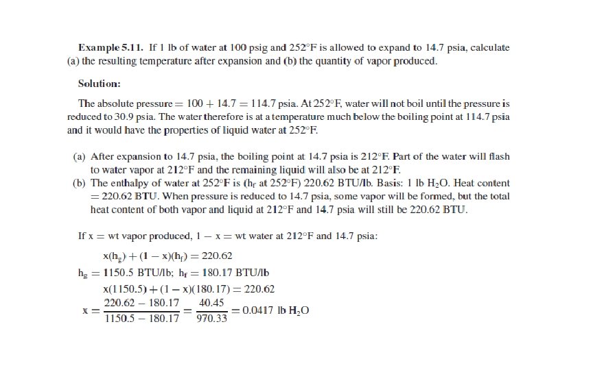
Calculate the volume of CO 2 in ft 3 at 70 o. F and 1 atm, which would be produced by vaporization of 1 lb of dry ice.
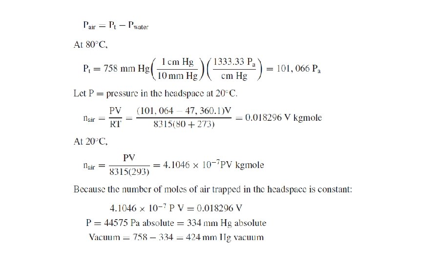
An empty can was sealed in a room at 80 o. C and 1 atm pressure. Assuming that only air is inside the sealed can, what will be the vacuum after the can and contents cool to 20 o. C? • Solution:
Calculate the quantity of air in the headspace of a can at 20 o. C when the vacuum in the can is 10 in. Hg. Atmospheric pressure is 30 in. Hg. The headspace has a volume of 16. 4 cm 3. The headspace is saturated with water vapor • vapor pressure of water at 20 o. C = 2336. 6 Pa. • Let Pt be the absolute pressure inside the can.
• Assume there are no dissolved gases in the product at the time of sealing, therefore the only gases in the headspace are air and water vapor. The vapor pressure of water at 20◦C and 80◦C are 2. 3366 and 47. 3601 k. Pa, respectively. In the gas mixture in the headspace, air is assumed to remain at the same quantity in the gaseous phase, while water condenses on cooling
A gas mixture used for controlled atmosphere storage of vegetables contains 5% CO 2, 5% O 2, and 90% N 2. The mixture is generated by mixing appropriate quantities of air and N 2 and CO 2 gases. 100 m 3 of this mixture at 20 o. C and 1 atm is needed per hour. Air contains 21% O 2 and 79% N 2. Calculate the volume at which the component gases must be metered into the system in m 3/h at 20 o. C and 1 atm. • All percentages are by volume. No volume changes occur on mixing of ideal gases. Because volume percent in gases is the same as mole percent, material balance equations may be made on the basis of volume and volume percentages. Let X = volume O 2, Y = volume CO 2, and Z = volume N 2, fed into the system per hour. • Oxygen balance: 0. 21(X) = 100(0. 05); X = 23. 8 m 3 • CO 2 balance: Y = 0. 05(100); Y = 5 m 3 • Total volumetric balance: X + Y + Z = 100 • Z = 100 − 23. 8 − 5 = 71. 2 m 3
Temperature Pressure (°C) 20 22 24 26 28 30 40 50 60 70 80 90 105 110 115 120 125 130 135 140 150 160 (k. Pa) 2. 34 2. 65 2. 99 3. 36 3. 78 4. 25 7. 38 12. 3 19. 9 31. 2 47. 4 70. 1 101. 35 120. 8 143. 3 169. 1 198. 5 232. 1 270. 1 313. 0 361. 3 475. 8 617. 8 Enthalpy (sat. vap. ) (k. J kg-1) 2538 2542 2545 2549 2553 2556 2574 2592 2610 2627 2644 2660 2676 2684 2692 2699 2706 2714 2721 2727 2734 2747 2758 Latent heat (k. J kg-1) 2454 2449 2445 2440 2435 2431 2407 2383 2359 2334 2309 2283 2257 2244 2230 2217 2203 2189 2174 2160 2145 2114 2083 Specific volume (m 3 kg-1) 57. 8 51. 4 45. 9 40. 0 36. 6 32. 9 19. 5 12. 0 7. 67 5. 04 3. 41 2. 36 1. 673 1. 42 1. 21 1. 04 0. 892 0. 771 0. 669 0. 582 0. 509 0. 393 0. 307
Heat • Sensible heat is defined as the energy transferred between two bodies at different temperatures, or the energy present in a body by virtue of its temperature. • Latent heat is the energy associated with phase transitions, heat of fusion, from solid to liquid, and heat of vaporization, from liquid to vapor. • Enthalpy, is an intrinsic property, the absolute value of which cannot be measured directly. • However, if a reference state is chosen for all components that enter and leave a system such that at this state the enthalpy is considered to be zero, then the change in enthalpy from the reference state to the current state of a component can be considered as the value of the absolute enthalpy for the system under consideration. • The reference temperature (Tref) for determining the enthalpy of water in the steam tables is 32. 018◦F or 0. 01◦C.
Specific Heat • The specific heat (Cp) is the amount of heat that accompanies a unit change in temperature for a unit mass. • The specific heat, which varies with temperature, is more variable for gases compared with liquids or solids. • Most solids and liquids have a constant specific heat over a fairly wide temperature range.
specific heat J/(kg K)
Estimation of Cp • Cavg = 3349 M+ 837. 36 in J/(kg K) for fat free plant material • Cavg = 1674. 72 F + 837. 36 SNF + 4 l 86. 8 M in J/(kg K) • the mass fraction fat (F), mass fraction solids non-fat (SNF), and mass fraction moisture (M) • Example: Calculate the heat required to raise the temperature of a 4. 535 kg roast beef containing 15% protein, 20% fat, and 65% water from 4. 44◦C to 65. 55◦C • Solution: • Cavg = 0. 15(837. 36) + 0. 2(1674. 72) + 0. 65(4186. 8) = 3182 J/(kg K) • q = 4. 535 kg[3182 J/(kg K)] (65. 55 − 4. 44)K = 0. 882 MJ
Specific heat of gas and vapor • where. Cpm is mean specific heat from the reference temperature To to T 1. Tabulated values for the mean specific heat of gases are based on ambient temperature of 77◦F or 25◦C, as the reference temperature.
Contoh • Hitung kebutuhan panas untuk menaikkan suhu udara pengering pd tekanan 1 atm dari suhu ruang 25 o. C ke suhu pengeringan 50 o. C jika tiap menit dialirkan udara sebanyak 100 m 3 • q= m. Cp (50 -25) • m=PVM/RT • R = 0. 08206 m 3 atm/kg mole K
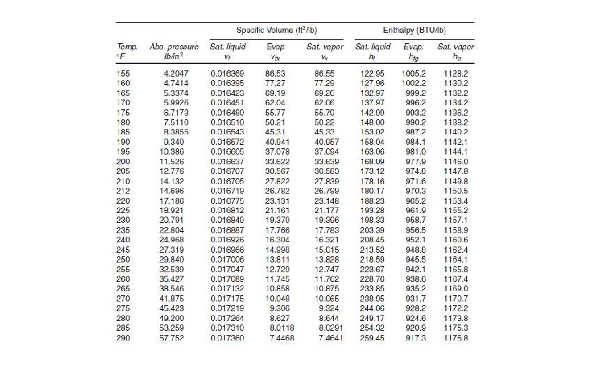
PROPERTIES OF SATURATED AND SUPERHEATED STEAM • • • Steam and water are the two most used heat transfer mediums in food processing. Water is also a major component of food products. The steam tables that list the properties of steam are a very useful reference when determining heat exchange involving a food product and steam or water. At temperatures above the freezing point, water can exist in either of the following forms. Saturated Liquid: . Liquid water in equilibrium with its vapor. The total pressure above the liquid must be equal to or be higher than the vapor pressure. If the total pressure above the liquid exceeds the vapor pressure, some other gas is present in the atmosphere above the liquid. If the total pressure above a liquid equals the vapor pressure, the liquid is at the boiling point. Saturated Vapor: This is also known as saturated steam and is vapor at the boiling temperature of the liquid. Lowering the temperature of saturated steam at constant pressure by a small increment will cause vapor to condense to liquid. The phase change is accompanied by a release of heat. If heat is removed from the system, temperature and pressure will remain constant until all vapor is converted to liquid. Adding heat to the system will change either temperature or pressure or both. Vapor-Liquid Mixtures: Steam with less than 100% quality. Temperature and pressure correspond to the boiling point; therefore, water could exist either as saturated liquid or saturated vapor. Addition of heat will not change temperature and pressure until all saturated liquid is converted to vapor. Removing heat from the system will also not change temperature and pressure until all vapor is converted to liquid. Steam Quality: The percentage of a vapor-liquid mixture that is in the form of saturated vapor. Superheated Steam: Water vapor at a temperature higher than the boiling point. The number of degrees the temperature exceeds the boiling temperature is the degrees superheat. Addition of heat to superheated steam could increase the superheat at constant pressure or change both the pressure and temperature at constant volume. Removing heat will allow the temperature to drop to the boiling temperature where the temperature will remain constant until all the vapor has condensed.
Steam table • The saturated steam table consists of entries under the headings of temperature, absolute pressure, specific volume, and enthalpy.
Temperature Pressure (°C) 20 22 24 26 28 30 40 50 60 70 80 90 105 110 115 120 125 130 135 140 150 160 (k. Pa) 2. 34 2. 65 2. 99 3. 36 3. 78 4. 25 7. 38 12. 3 19. 9 31. 2 47. 4 70. 1 101. 35 120. 8 143. 3 169. 1 198. 5 232. 1 270. 1 313. 0 361. 3 475. 8 617. 8 Enthalpy (sat. vap. ) (k. J kg-1) 2538 2542 2545 2549 2553 2556 2574 2592 2610 2627 2644 2660 2676 2684 2692 2699 2706 2714 2721 2727 2734 2747 2758 Latent heat (k. J kg-1) 2454 2449 2445 2440 2435 2431 2407 2383 2359 2334 2309 2283 2257 2244 2230 2217 2203 2189 2174 2160 2145 2114 2083 Specific volume (m 3 kg-1) 57. 8 51. 4 45. 9 40. 0 36. 6 32. 9 19. 5 12. 0 7. 67 5. 04 3. 41 2. 36 1. 673 1. 42 1. 21 1. 04 0. 892 0. 771 0. 669 0. 582 0. 509 0. 393 0. 307
contoh • Pada tekanan vakum berapa sehingga air mendidih pada suhu 80 o. C, nyatakan dalam k. Pa dan dalam cm Hg – Lihat tabel uap= 47, 4 k. Pa abs – Tekanan vakum = 101 - 47, 4 = 53, 6 k. Pa – Tekanan vakum = (53, 6/101) x 76 = 40, 3 cm. Hg • Sterilisasi dilakukan pada suhu 120 o. C, berapa tekanan yang terbaca pada manometer yang menggunakan satuan psi? – Dari tabel pada suhu 120 o. C tekanan uap = 198, 5 k. Pa, maka tekanan pada manometer = 198, 5 – 101 = 97, 5 k. Pa – 1 atm = 14, 7 psi = 101 k. Pa – Tekanan pada manometer = (97, 5/101) x 14, 7 = 14, 2 psig