Darcys Law and Application Darcys empirical flow law


")

 Calculate the maximum possible")
 relationships : ; ; ; Productivity Index")


 The method shown requires a preflush to condition the reservoir, the")

- Slides: 79
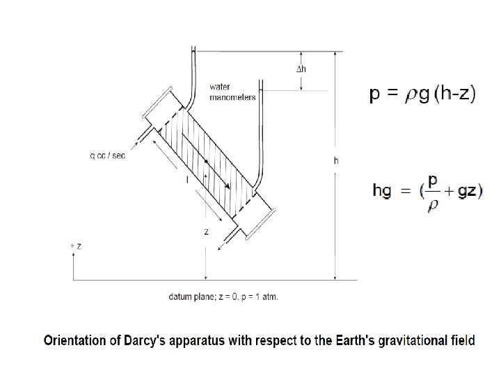
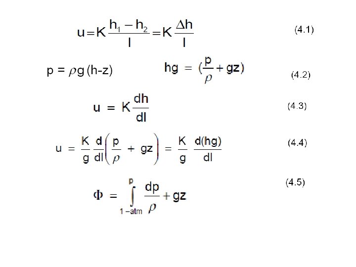
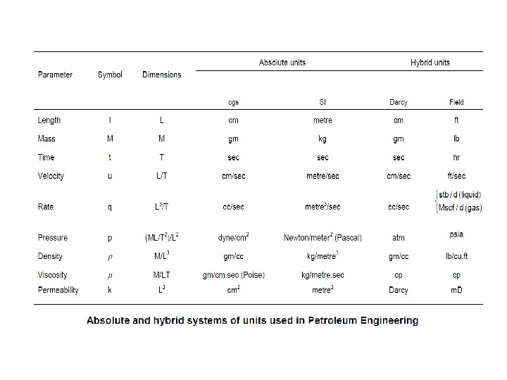
Darcy’s Law and Application Darcy’s empirical flow law was first extension of the principles of classical fluid dynamics to the flow of fluids through porous media. • In 1856 Darcy published a detailed account of his work in improving the water works in Dijon • In particular, on the design of a filter large enough to process the town’s daily water requirements. • Although fluid dynamics was a fairly advanced subject in those days • There were no published accounts of the phenomenon of fluid flow through a porous medium • Darcy designed a filter shown schematically below in figure in an attempt to investigate the matter.
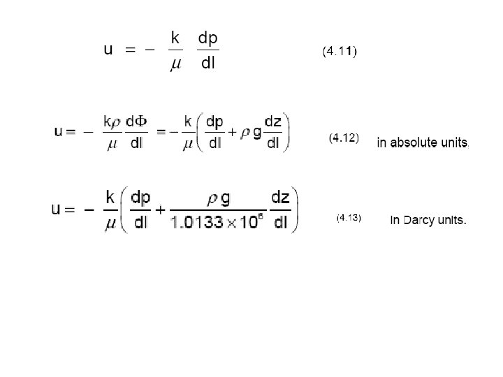
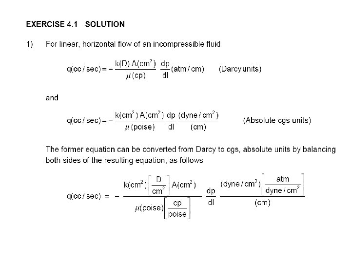
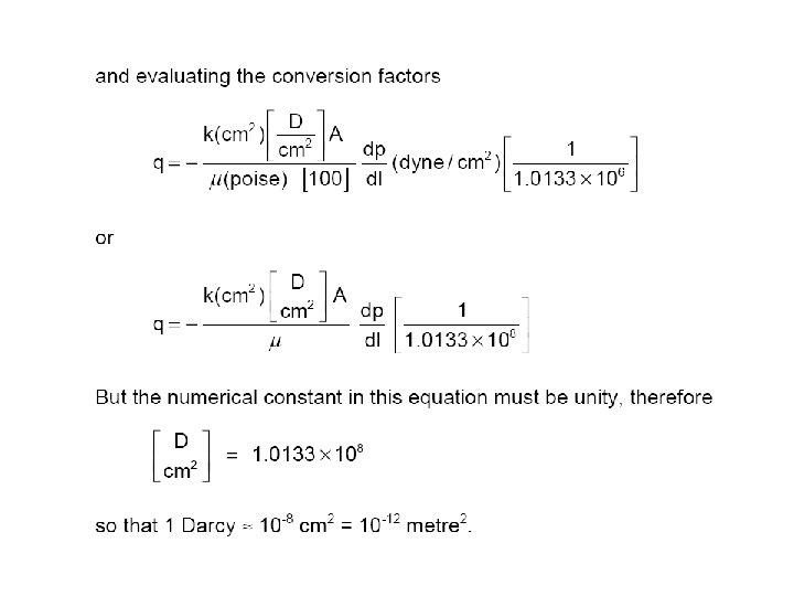
Darcy’s law for horizontal, Linear flow of an incompressible fluid
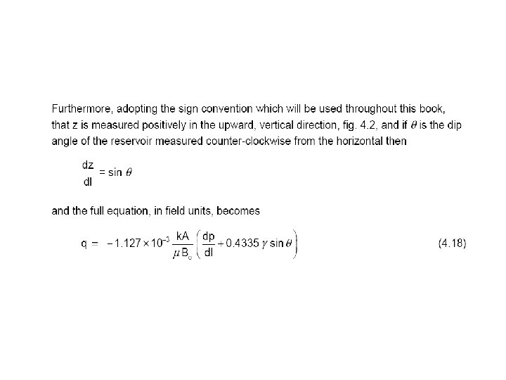
(4. 12)
Datum Pressures
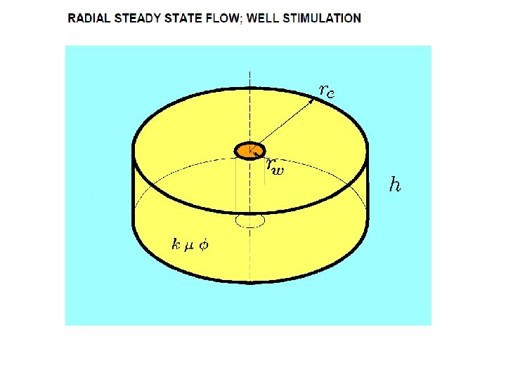
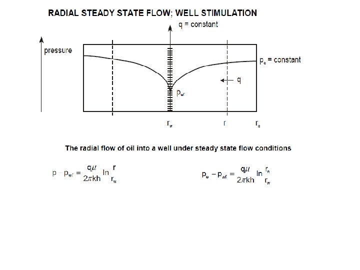
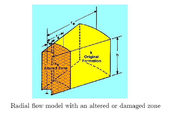
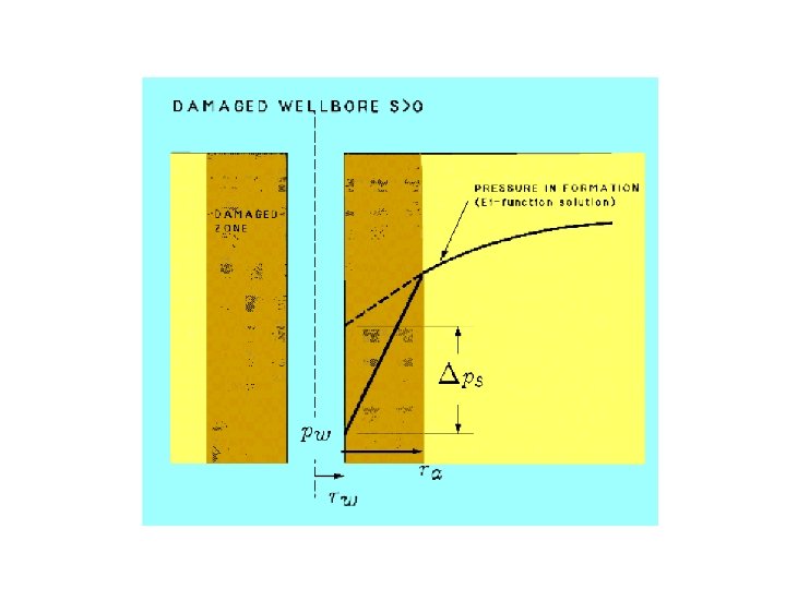
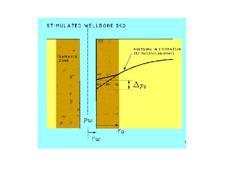
Assignment : Steady state radial flow with skin Q. (i) Calculate the maximum possible pumping rate for an oil well in a reservoir where the pressure is being maintained at 2000 psia at drainage radius. A well test has shown the well to be highly damaged with a skin factor +7. The following data apply: k=230 m. D, h=10, µ=3. 5, rw=0. 5 ft, re= 2000 ft (ii) What would the well rate be if the wellbore is cleaned with acid. A successful job may reduce the skin factor to approximately zero. (iii)What would the rate be for a stimulated well after a frac job which is expected to achieve a skin factor of -3.
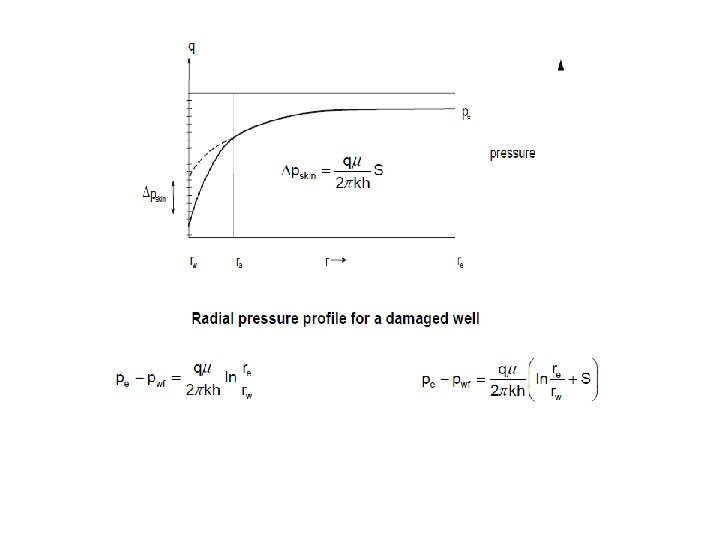
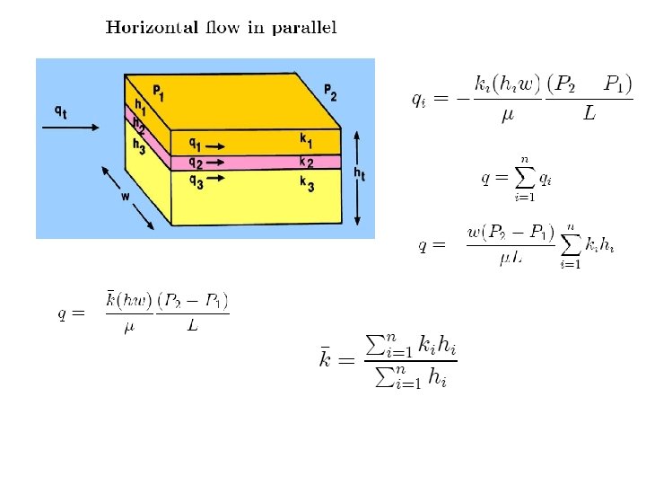
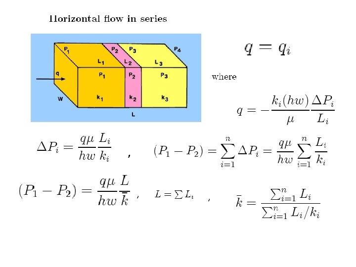
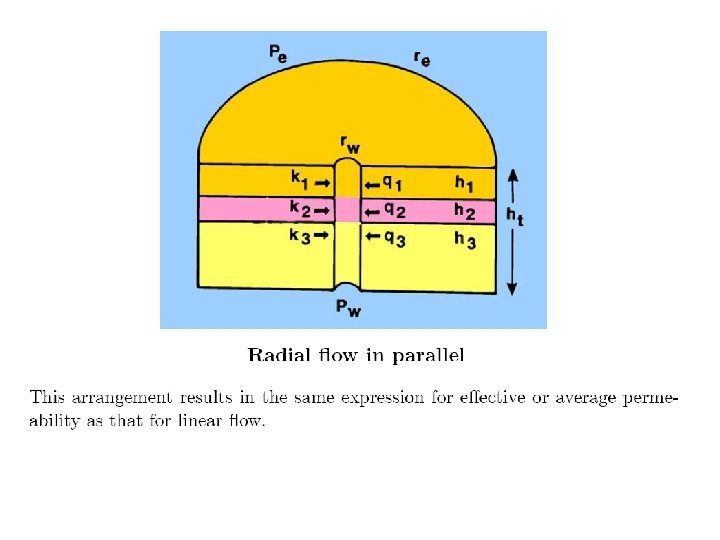
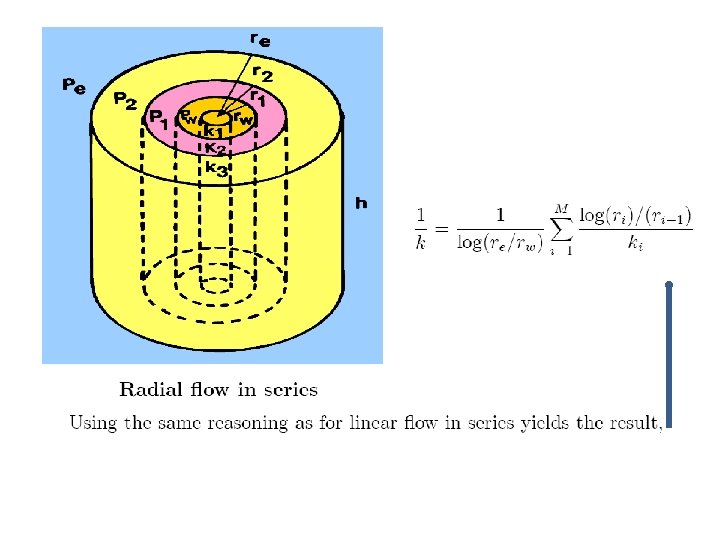
Some important ( derived ) relationships : ; ; ; Productivity Index
Productivity Enhancement
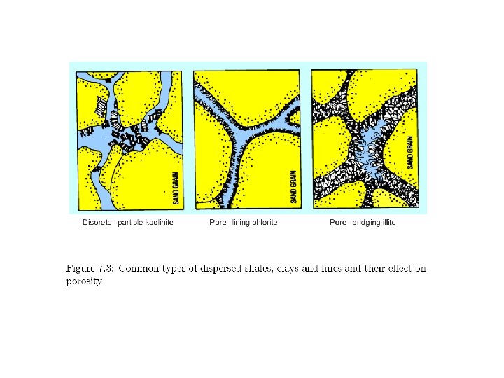
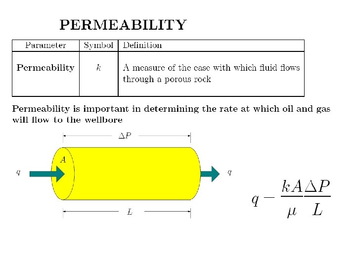
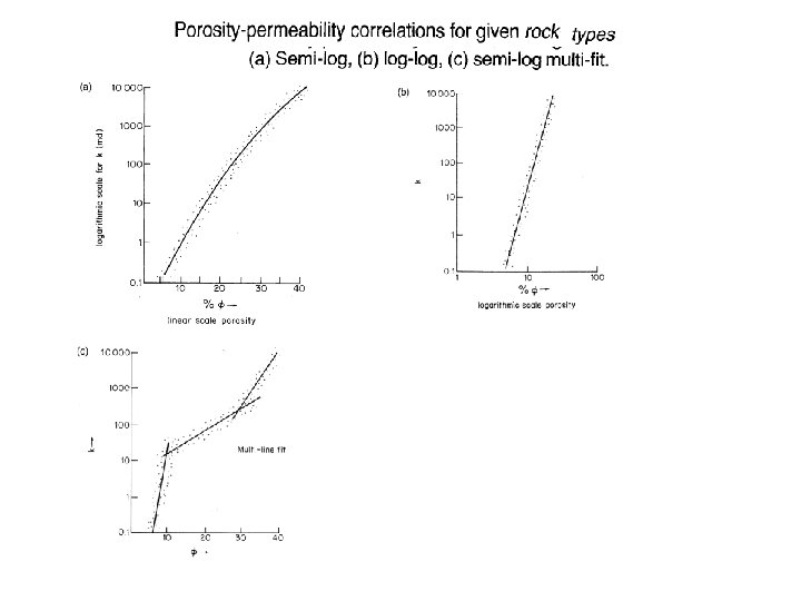
Rock Properties : Porosity, Permeability
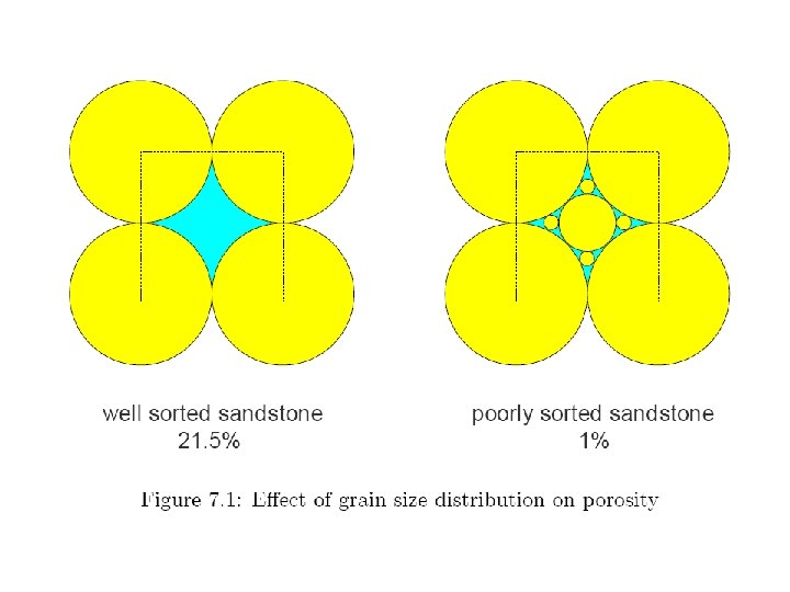
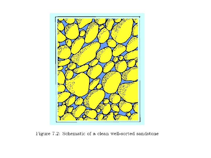
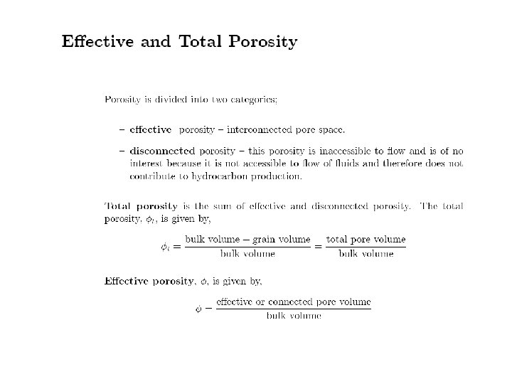
ROCK PROPERTIES • Porosity : • Porosity of rock is the ratio of pore volume to bulk volume. • Porosity is generally expressed as a percentage of bulk volume. • Porosity of rock is. Where V p is pore volume, Vb is bulk volume &Vg is grain volume Where Vp is pore volume Vb is bulk volume & Vg is grain volume
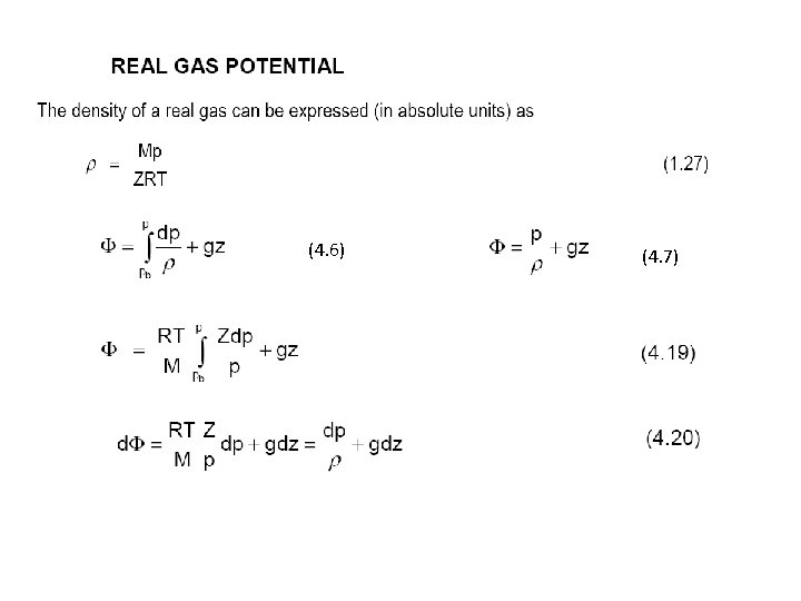
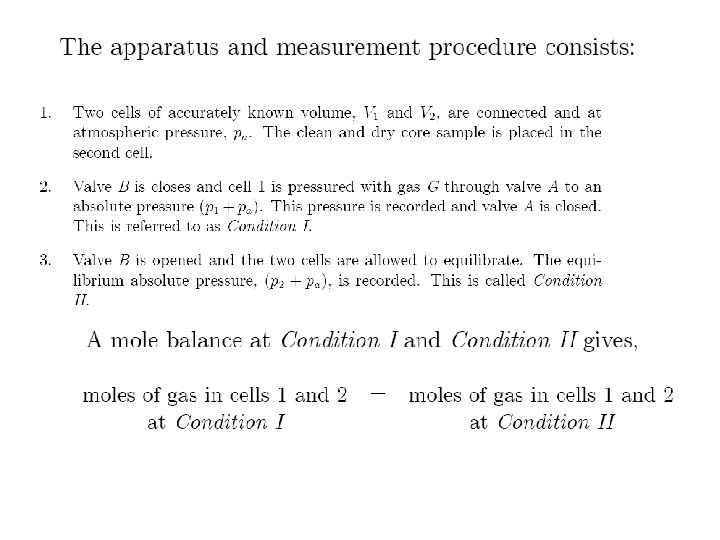
Ideal gas Law:
Problem :
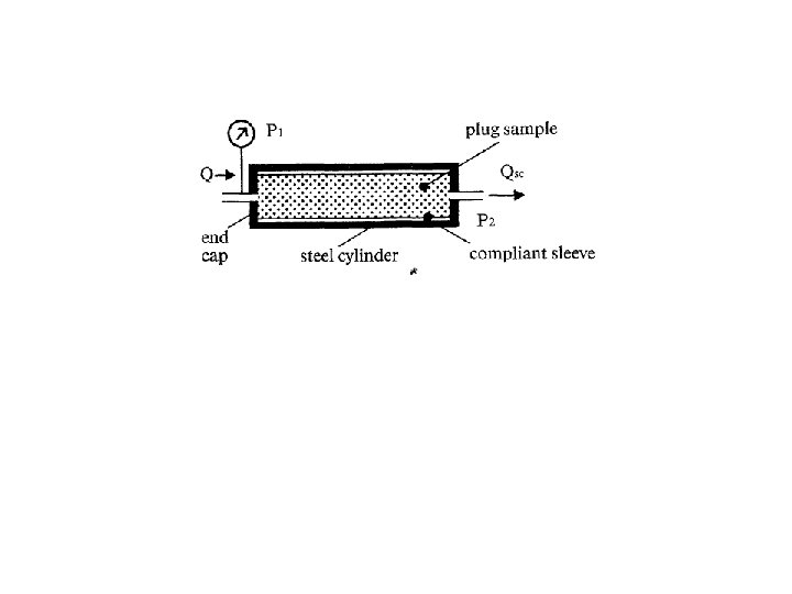
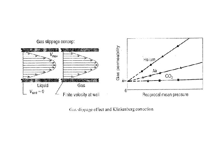
Using gas as working fluid
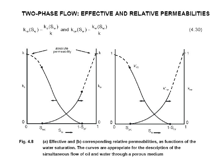
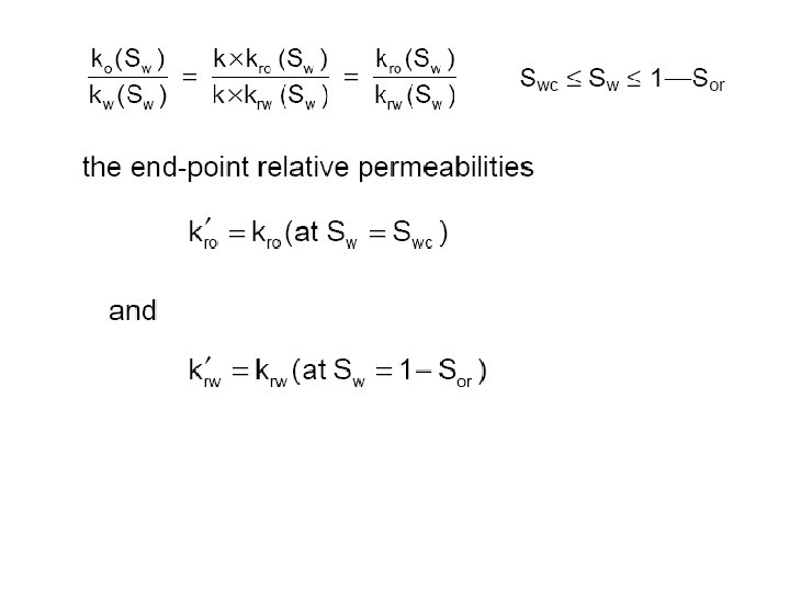
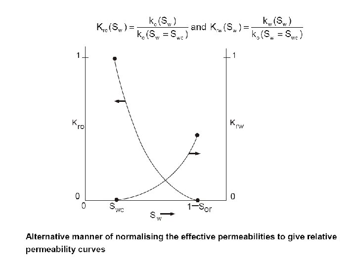
the normalised relative permeability curves are defined as
Secondary Recovery Predictions of future reservoir performance are required, amongst other things, to identify the need and timing for secondary gas or water injection. Useful estimates of future production trends can be obtained from a knowledge of: (i) The size of the gas cap relative to the size of the oil reservoir. (ii) The size of the aquifer relative to the size of the oil zone. (iii) Formation permeability can be estimated from core data and flow tests on wells. Drill-stem tests on dry holes and structurally low wells (wells penetrating the aquifer) may yield important indications of aquifer permeability and continuity. Sometimes it is useful to complete dry holes as aquifer observation wells. Pressure data from such wells can be important in characterizing reservoir aquifer systems. The aquifer can have a profound effect on reservoir performance.
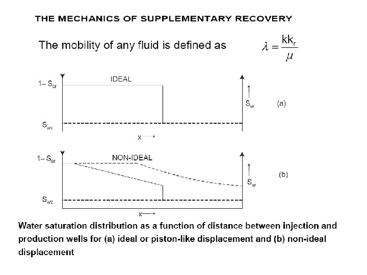
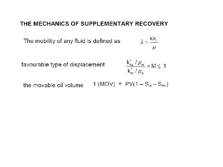
Favourable Type of displacement will occur only if :
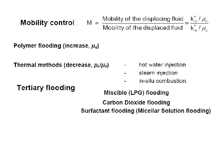
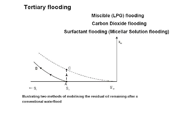
Tertiary Recovery — EOR Processes The same techniques used to determine the need for secondary recovery are used to assess the need for tertiary developments. Decisions regarding the actual im plementation of EOR processes are not made until sufficient field data is available to accurately assess primary and secondary performance. EOR processes may be classified into three major categories: Chemical : Micellar Polymer Flooding Caustic or Alkaline Flooding Thermal Steam Flooding Fire Flooding Miscible Enriched Hydrocarbon Gas Flooding CO 2 Flooding Nitrogen and Flue Gas Flooding The complexity of these processes requires the gathering of large quantities of ad ditional laboratory fluid and core data and the use of considerably more complex analysis techniques.
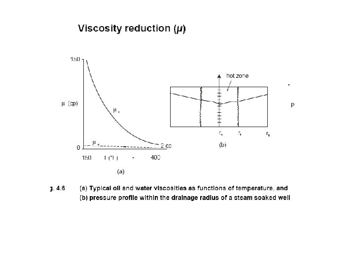
Heat, from steam injected into a heavy-oil reservoir, thins the oil making it easier for the steam to push the oil through the formation toward production wells. Heat reduces viscosity of oil and increases its mobility. Steam flooding process
Carbon dioxide flooding process
CHEMICAL FLOODING (Polymer) The method shown requires a preflush to condition the reservoir, the injection of a polymer solution for mobility control to minimize channeling, and a driving fluid (water) to move the polymer solution and resulting oil bank to production wells. Chemical flooding process