
Darcy Lab Describe Apparatus Q cm 3sec K
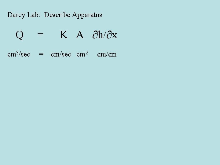
Darcy Lab: Describe Apparatus Q = cm 3/sec = K A ∂h/∂x cm/sec cm 2 cm/cm
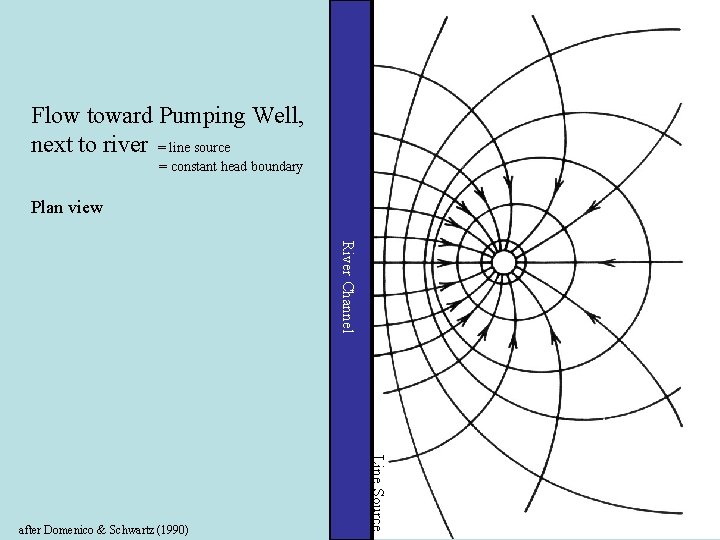
Flow toward Pumping Well, next to river = line source = constant head boundary Plan view River Channel Line Source after Domenico & Schwartz (1990)
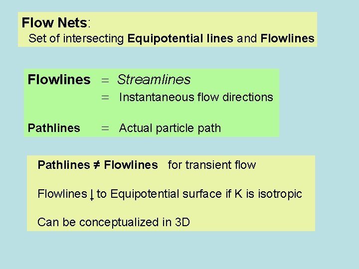
Flow Nets: Set of intersecting Equipotential lines and Flowlines = Streamlines = Instantaneous flow directions Pathlines = Actual particle path Pathlines ≠ Flowlines for transient flow Flowlines | to Equipotential surface if K is isotropic Can be conceptualized in 3 D
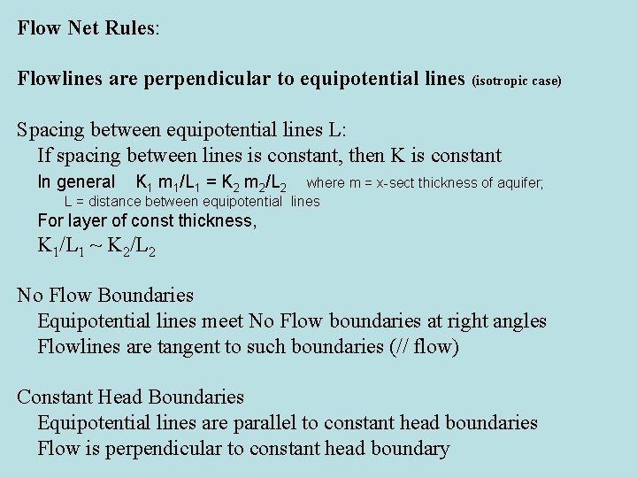
Flow Net Rules: Flowlines are perpendicular to equipotential lines (isotropic case) Spacing between equipotential lines L: If spacing between lines is constant, then K is constant In general K 1 m 1/L 1 = K 2 m 2/L 2 where m = x-sect thickness of aquifer; L = distance between equipotential lines For layer of const thickness, K 1/L 1 ~ K 2/L 2 No Flow Boundaries Equipotential lines meet No Flow boundaries at right angles Flowlines are tangent to such boundaries (// flow) Constant Head Boundaries Equipotential lines are parallel to constant head boundaries Flow is perpendicular to constant head boundary
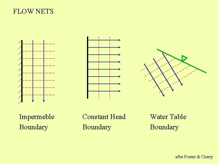
FLOW NETS Impermeble Boundary Constant Head Boundary Water Table Boundary after Freeze & Cherry
MK Hubbert 1903 -1989 http: //photos. aip. org/
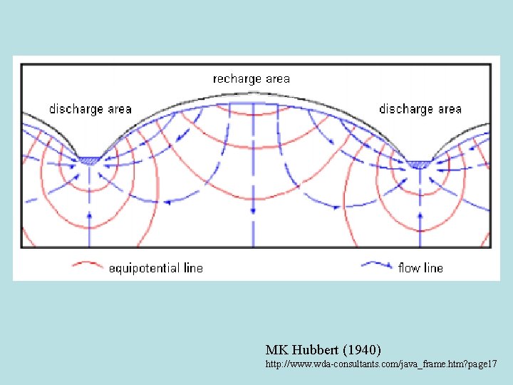
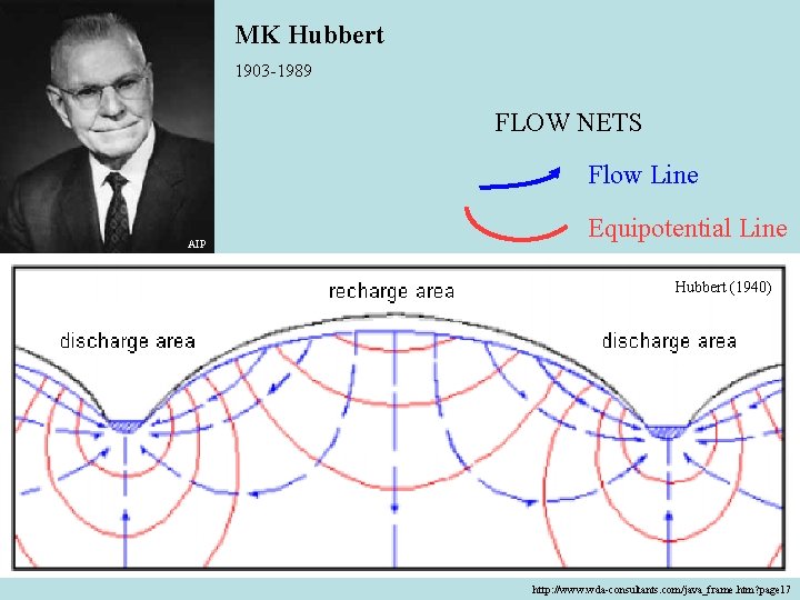
MK Hubbert (1940) http: //www. wda-consultants. com/java_frame. htm? page 17
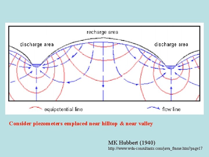
Consider piezometers emplaced near hilltop & near valley MK Hubbert (1940) http: //www. wda-consultants. com/java_frame. htm? page 17
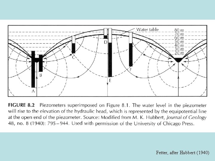
Fetter, after Hubbert (1940)
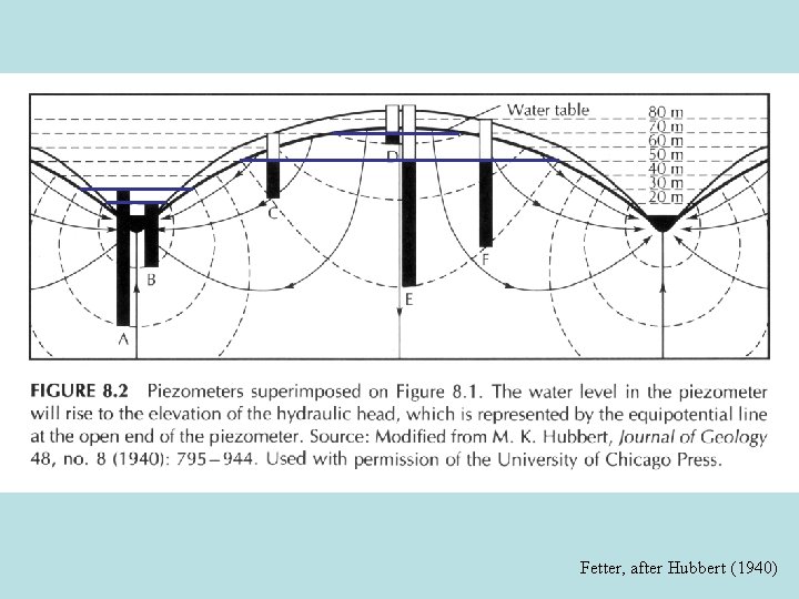
Fetter, after Hubbert (1940)
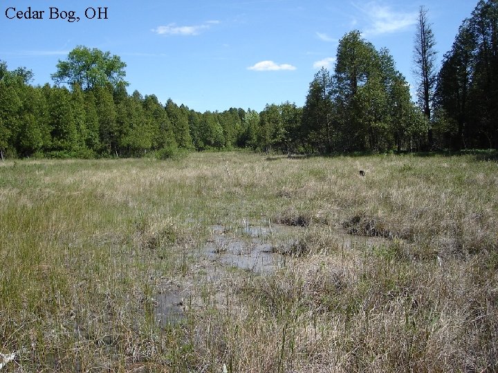
Cedar Bog, OH
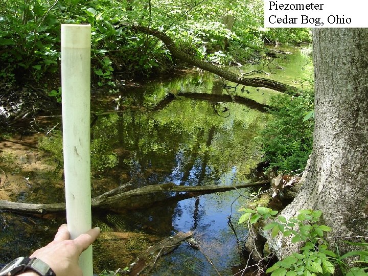
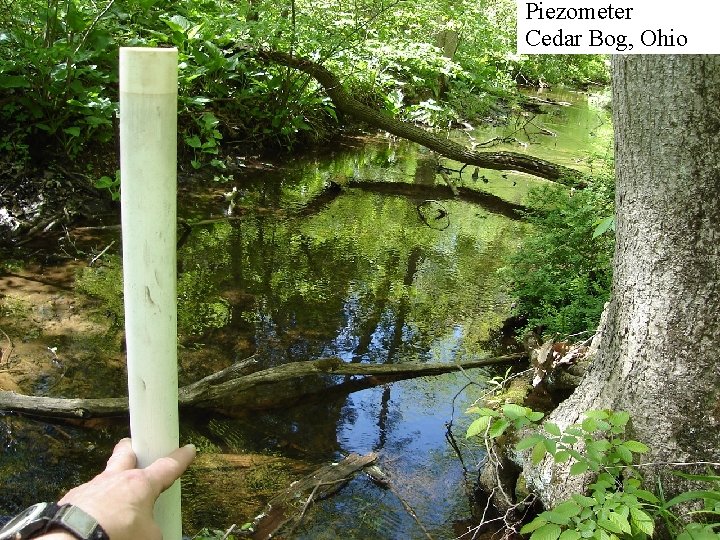
Piezometer Cedar Bog, Ohio
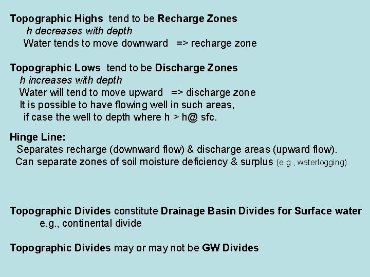
Topographic Highs tend to be Recharge Zones h decreases with depth Water tends to move downward => recharge zone Topographic Lows tend to be Discharge Zones h increases with depth Water will tend to move upward => discharge zone It is possible to have flowing well in such areas, if case the well to depth where h > h@ sfc. Hinge Line: Separates recharge (downward flow) & discharge areas (upward flow). Can separate zones of soil moisture deficiency & surplus (e. g. , waterlogging). Topographic Divides constitute Drainage Basin Divides for Surface water e. g. , continental divide Topographic Divides may or may not be GW Divides
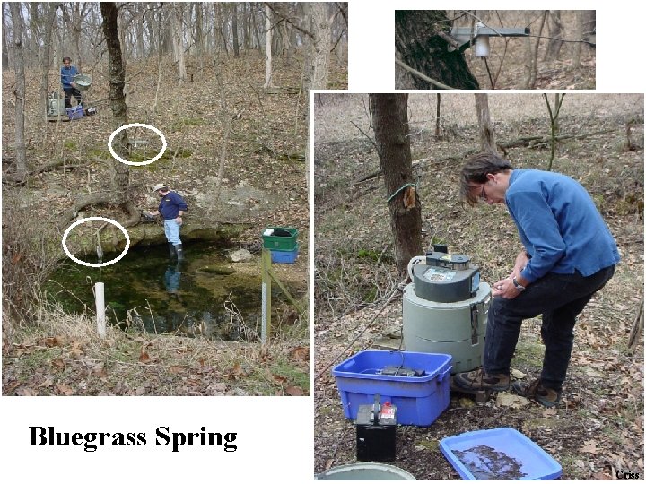
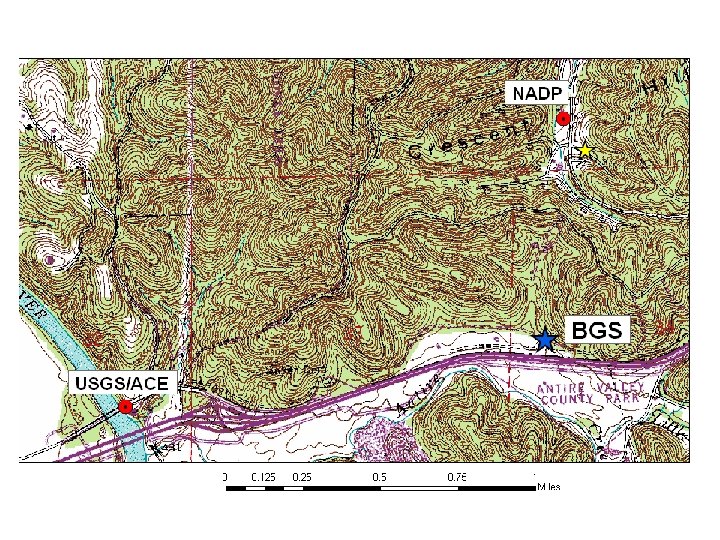
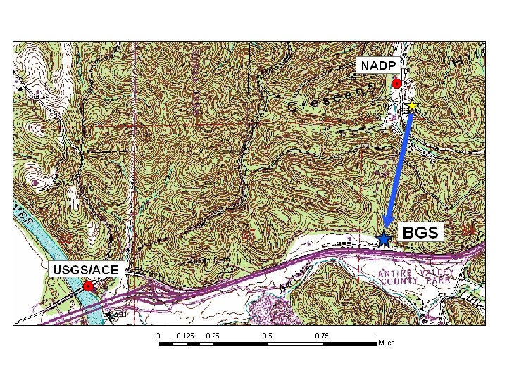
Bluegrass Spring Criss
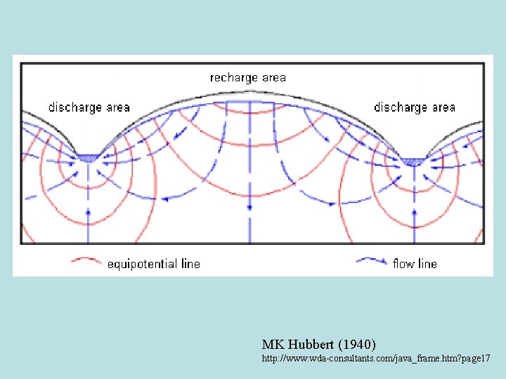
MK Hubbert (1940) http: //www. wda-consultants. com/java_frame. htm? page 17
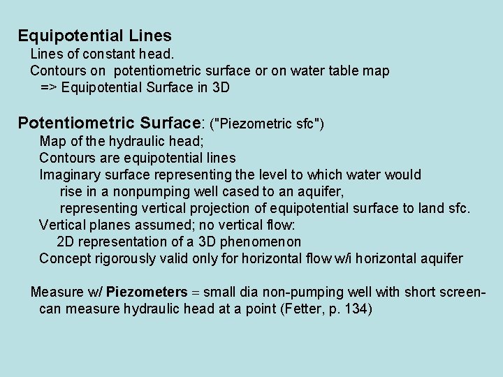
Equipotential Lines of constant head. Contours on potentiometric surface or on water table map => Equipotential Surface in 3 D Potentiometric Surface: ("Piezometric sfc") Map of the hydraulic head; Contours are equipotential lines Imaginary surface representing the level to which water would rise in a nonpumping well cased to an aquifer, representing vertical projection of equipotential surface to land sfc. Vertical planes assumed; no vertical flow: 2 D representation of a 3 D phenomenon Concept rigorously valid only for horizontal flow w/i horizontal aquifer Measure w/ Piezometers = small dia non-pumping well with short screencan measure hydraulic head at a point (Fetter, p. 134)

How do we know basic flownet picture is correct?
How do we know basic flownet picture is correct? Mathematical solutions (Toth, 1962, 1963) Numerical Simulations Data
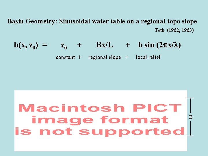
Basin Geometry: Sinusoidal water table on a regional topo slope Toth (1962, 1963) h(x, z 0) = z 0 + constant + Bx/L + regional slope + b sin (2 px/l) local relief B
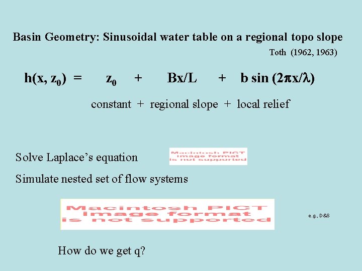
Basin Geometry: Sinusoidal water table on a regional topo slope Toth (1962, 1963) h(x, z 0) = z 0 + Bx/L + b sin (2 px/l) constant + regional slope + local relief Solve Laplace’s equation Simulate nested set of flow systems e. g. , D&S How do we get q?
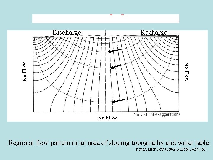
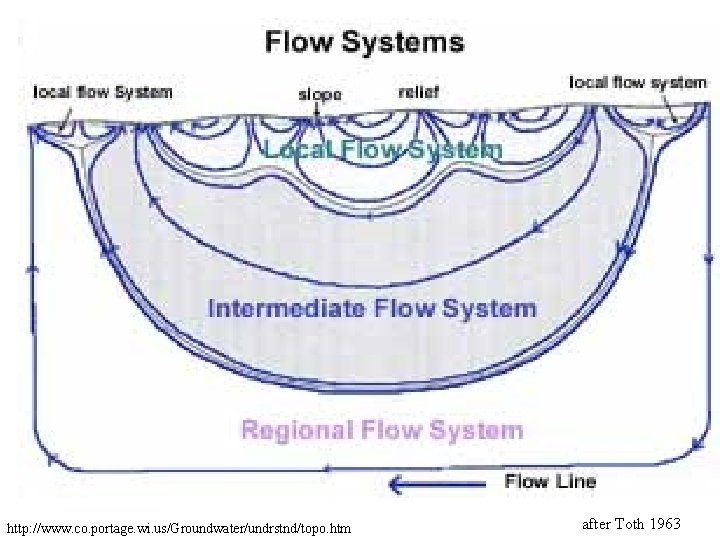
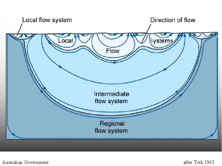
Discharge No Flow Recharge No Flow Regional flow pattern in an area of sloping topography and water table. Fetter, after Toth (1962) JGR 67, 4375 -87.
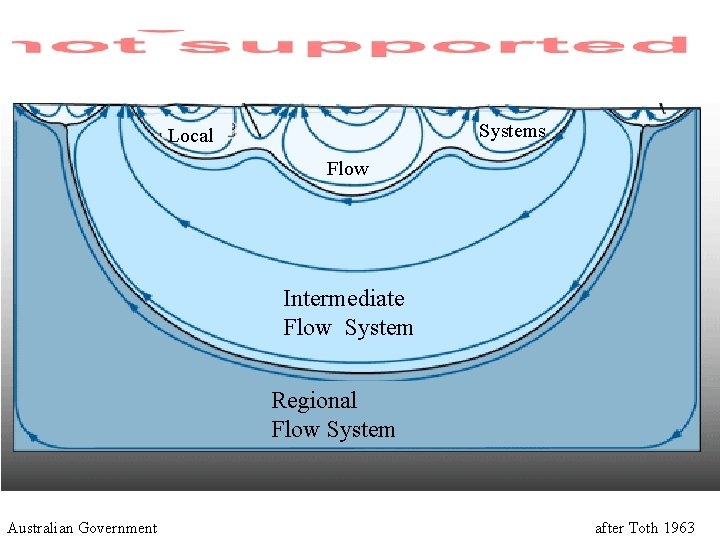
Systems Local Flow Intermediate Flow System Regional Flow System Australian Government after Toth 1963
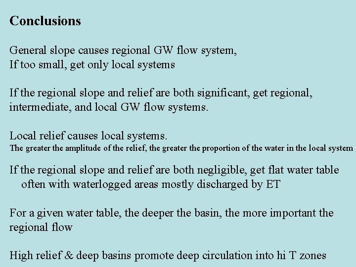
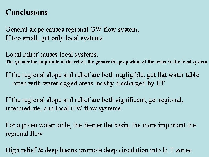
Conclusions General slope causes regional GW flow system, If too small, get only local systems If the regional slope and relief are both significant, get regional, intermediate, and local GW flow systems. Local relief causes local systems. The greater the amplitude of the relief, the greater the proportion of the water in the local system If the regional slope and relief are both negligible, get flat water table often with waterlogged areas mostly discharged by ET For a given water table, the deeper the basin, the more important the regional flow High relief & deep basins promote deep circulation into hi T zones
End 24 Begin 25
MK Hubbert 1903 -1989 FLOW NETS Flow Line AIP Equipotential Line Hubbert (1940) http: //www. wda-consultants. com/java_frame. htm? page 17
How do we know basic flownet picture is correct? Data Mathematical solutions (Toth, 1962, 1963) Numerical Simulations
Piezometer Cedar Bog, Ohio
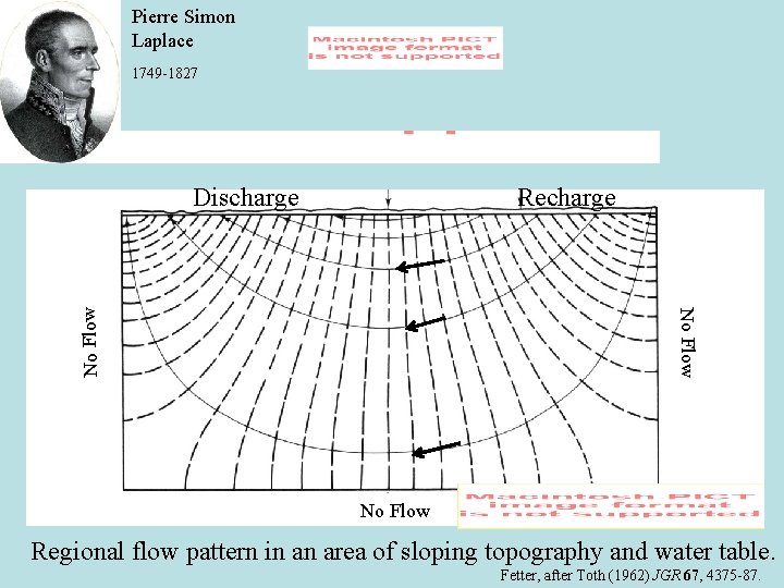
Pierre Simon Laplace 1749 -1827 Discharge No Flow Recharge No Flow Regional flow pattern in an area of sloping topography and water table. Fetter, after Toth (1962) JGR 67, 4375 -87.
Numerical Simulations Basically reproduce Toth’s patterns High K layers act as “pirating agents Refraction of flow lines tends to align flow parallel to hi K layer, and perpendicular to low K layers
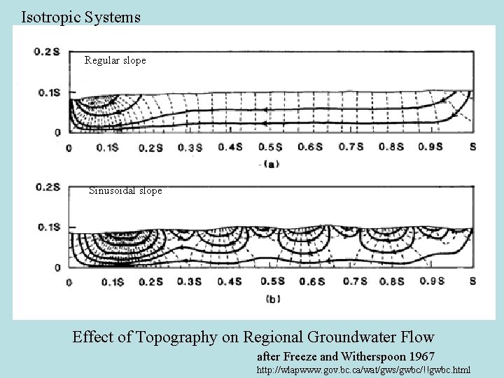
Isotropic Systems Regular slope Sinusoidal slope Effect of Topography on Regional Groundwater Flow after Freeze and Witherspoon 1967 http: //wlapwww. gov. bc. ca/wat/gws/gwbc/!!gwbc. html
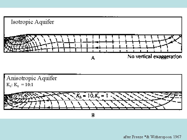
Isotropic Aquifer Anisotropic Aquifer Kx: Kz = 10: 1 after Freeze *& Witherspoon 1967
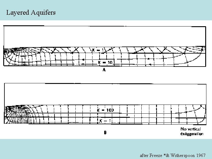
Layered Aquifers after Freeze *& Witherspoon 1967
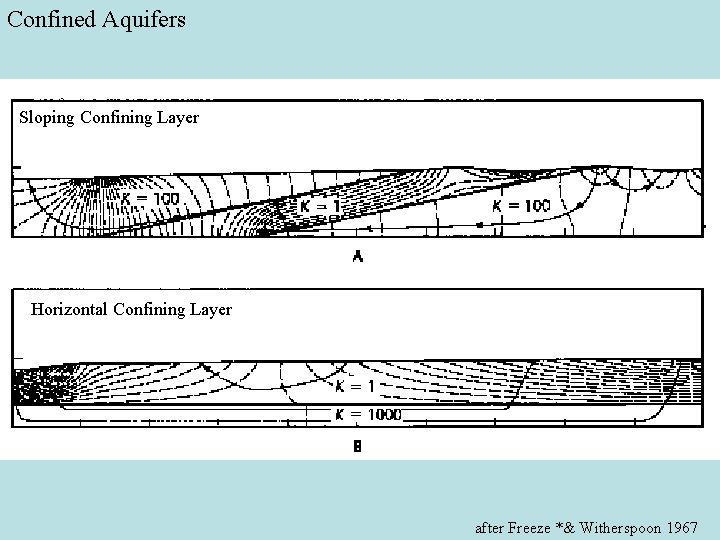
Confined Aquifers Sloping Confining Layer Horizontal Confining Layer after Freeze *& Witherspoon 1967
Conclusions General slope causes regional GW flow system, If too small, get only local systems Local relief causes local systems. The greater the amplitude of the relief, the greater the proportion of the water in the local system If the regional slope and relief are both negligible, get flat water table often with waterlogged areas mostly discharged by ET If the regional slope and relief are both significant, get regional, intermediate, and local GW flow systems. For a given water table, the deeper the basin, the more important the regional flow High relief & deep basins promote deep circulation into hi T zones
Flow in a Horizontal Layers Case 1: Steady Flow in a Horizontal Confined Aquifer Darcy Velocity q: Flow/ unit width: Typically have equally-spaced equipotential lines
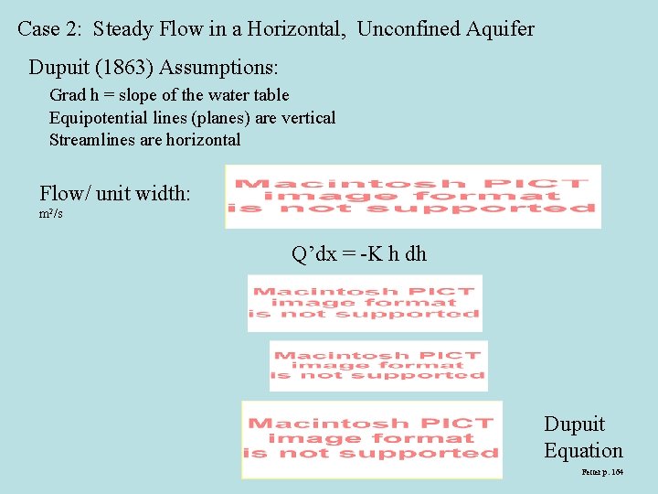
Case 2: Steady Flow in a Horizontal, Unconfined Aquifer Dupuit (1863) Assumptions: Grad h = slope of the water table Equipotential lines (planes) are vertical Streamlines are horizontal Flow/ unit width: m 2/s Q’dx = -K h dh Dupuit Equation Fetter p. 164
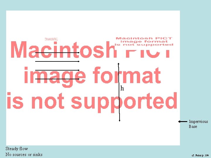
h Impervious Base Steady flow No sources or sinks cf. Fetter p. 164
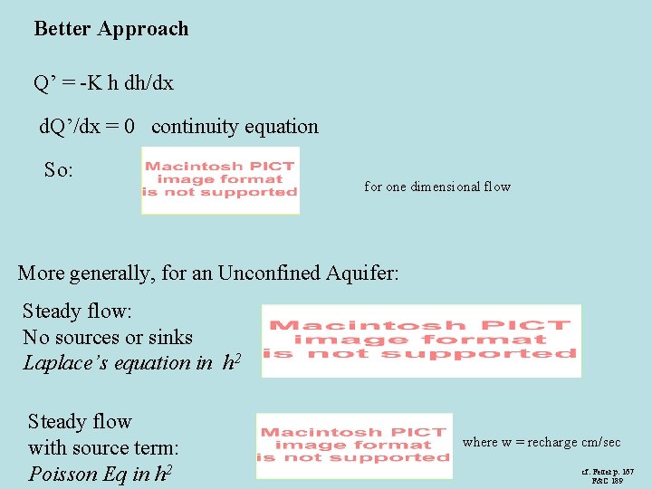
Better Approach Q’ = -K h dh/dx d. Q’/dx = 0 continuity equation So: for one dimensional flow More generally, for an Unconfined Aquifer: Steady flow: No sources or sinks Laplace’s equation in h 2 Steady flow with source term: Poisson Eq in h 2 where w = recharge cm/sec cf. Fetter p. 167 F&C 189
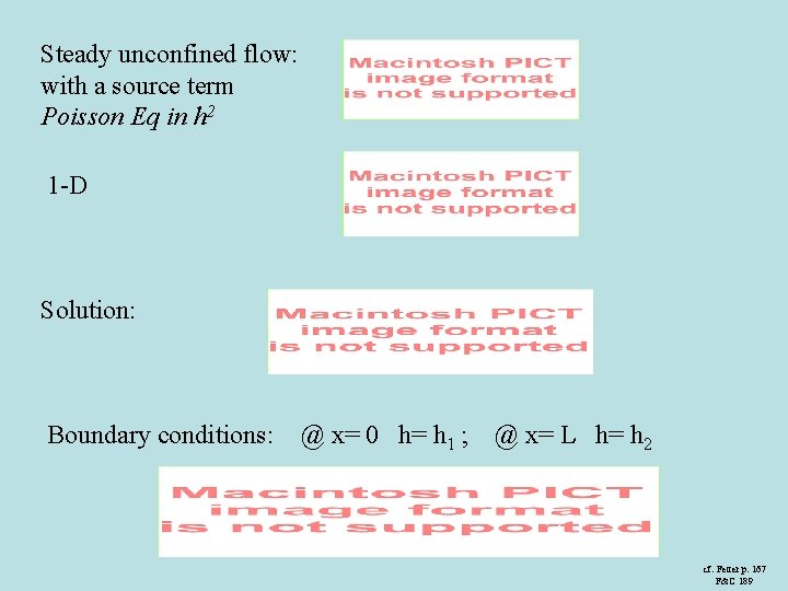
Steady unconfined flow: with a source term Poisson Eq in h 2 1 -D Solution: Boundary conditions: @ x= 0 h= h 1 ; @ x= L h= h 2 cf. Fetter p. 167 F&C 189
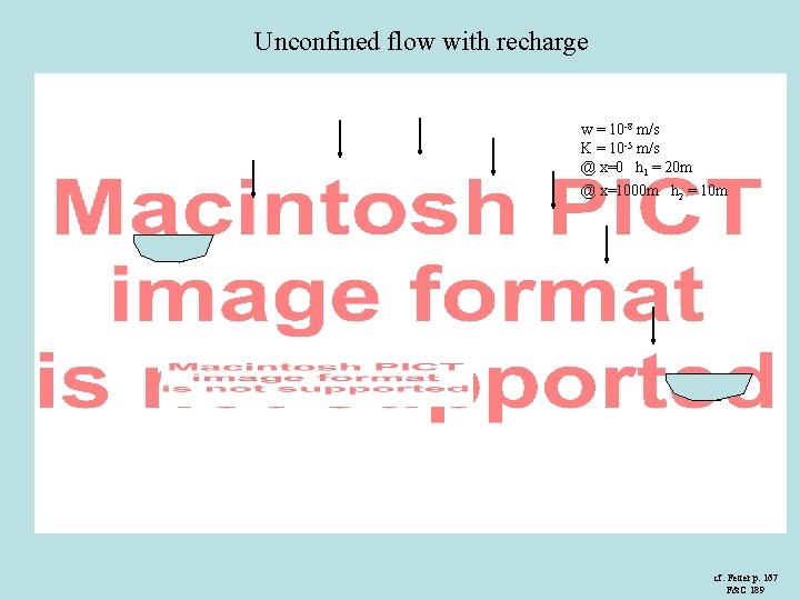
Unconfined flow with recharge w = 10 -8 m/s K = 10 -5 m/s @ x=0 h 1 = 20 m @ x=1000 m h 2 = 10 m w cf. Fetter p. 167 F&C 189
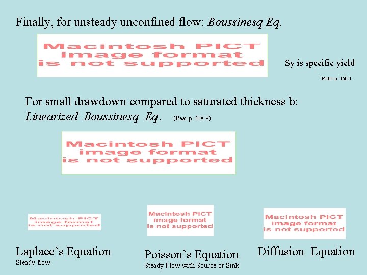
Finally, for unsteady unconfined flow: Boussinesq Eq. Sy is specific yield Fetter p. 150 -1 For small drawdown compared to saturated thickness b: Linearized Boussinesq Eq. (Bear p. 408 -9) Laplace’s Equation Steady flow Poisson’s Equation Steady Flow with Source or Sink Diffusion Equation

End Part II


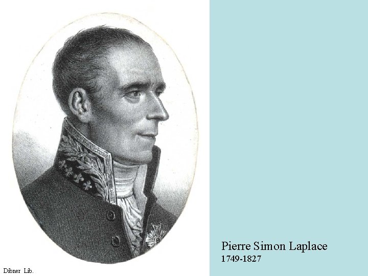
Pierre Simon Laplace 1749 -1827 Dibner Lib.
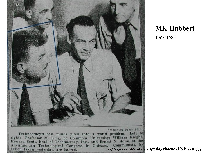
MK Hubbert 1903 -1989 http: //upload. wikimedia. org/wikipedia/en/f/f 7/Hubbert. jpg
Leonhard Euler 1707 - 1783 wikimedia. org
Charles V. Theis 19 -19 http: //photos. aip. org/

for unconfined flow
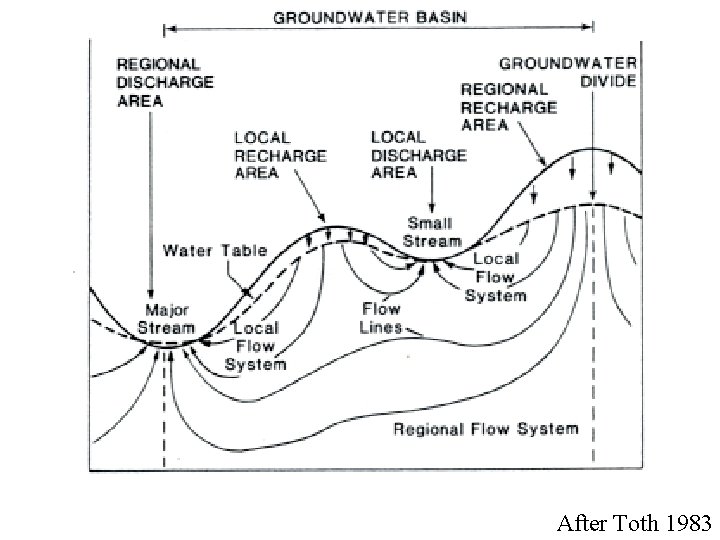
After Toth 1983
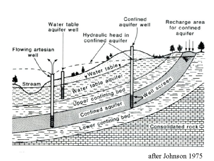
after Johnson 1975
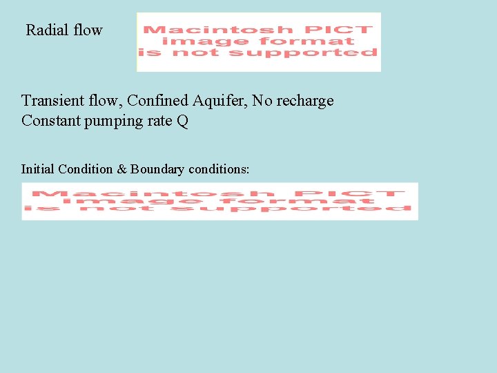
Radial flow Transient flow, Confined Aquifer, No recharge Constant pumping rate Q Initial Condition & Boundary conditions:
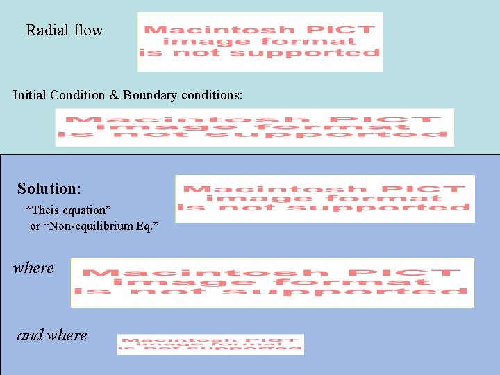
Radial flow Initial Condition & Boundary conditions: Solution: “Theis equation” or “Non-equilibrium Eq. ” where and where
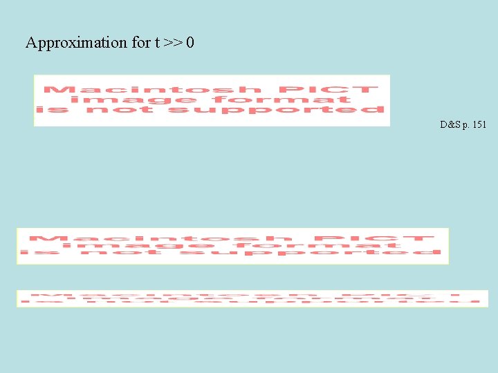
Approximation for t >> 0 D&S p. 151
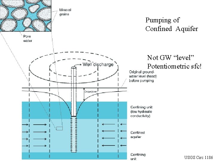
Pumping of Confined Aquifer Not GW “level” Potentiometric sfc! USGS Circ 1186
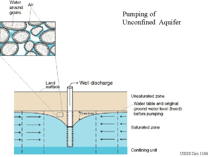
Pumping of Unconfined Aquifer USGS Circ 1186
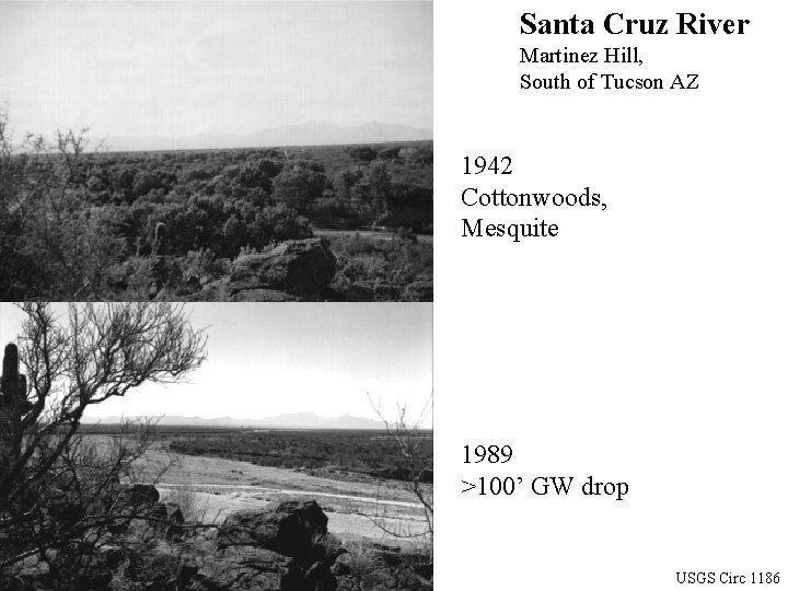
Santa Cruz River Martinez Hill, South of Tucson AZ 1942 Cottonwoods, Mesquite 1989 >100’ GW drop USGS Circ 1186

for unconfined flow
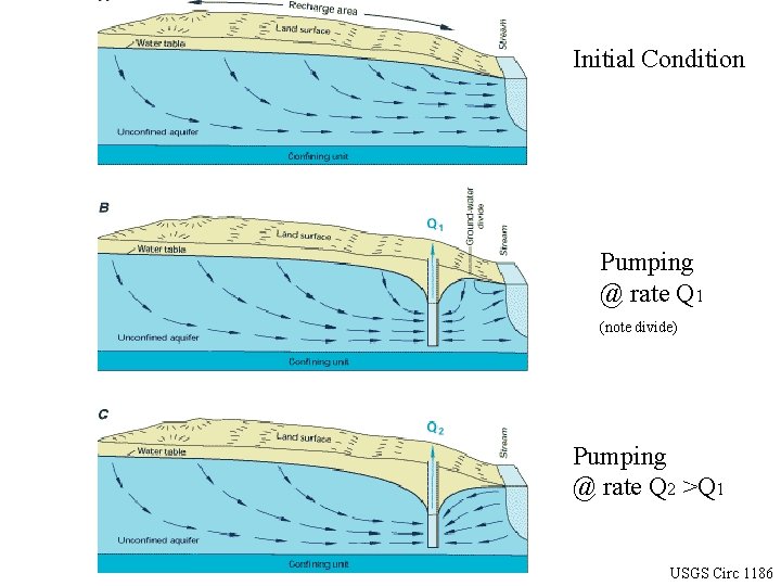
Initial Condition Pumping @ rate Q 1 (note divide) Pumping @ rate Q 2 >Q 1 USGS Circ 1186

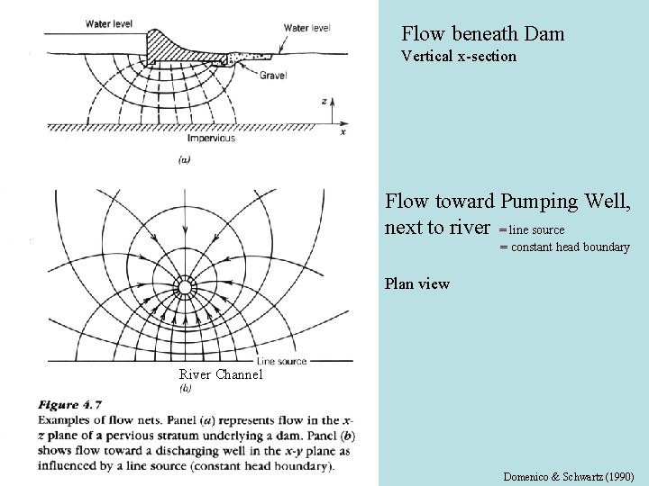
Flow beneath Dam Vertical x-section Flow toward Pumping Well, next to river = line source = constant head boundary Plan view River Channel Domenico & Schwartz (1990)
http: //www. co. portage. wi. us/Groundwater/undrstnd/topo. htm after Toth 1963
Australian Government after Toth 1963
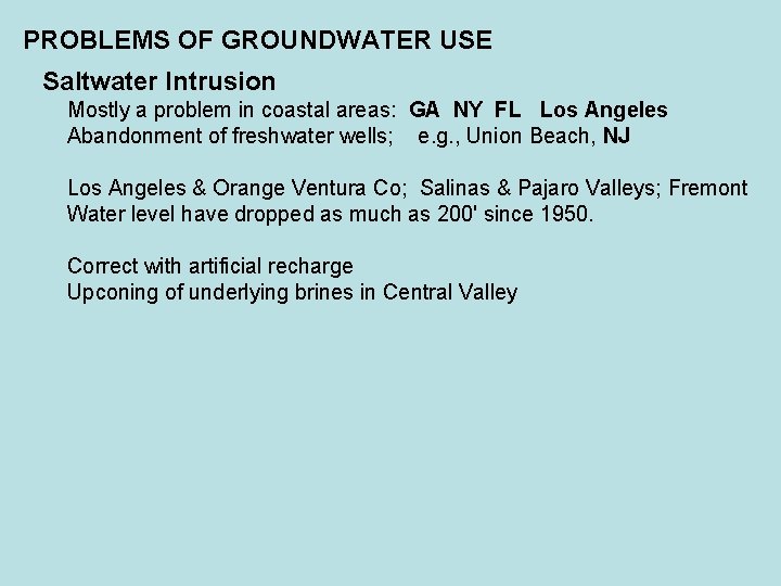
PROBLEMS OF GROUNDWATER USE Saltwater Intrusion Mostly a problem in coastal areas: GA NY FL Los Angeles Abandonment of freshwater wells; e. g. , Union Beach, NJ Los Angeles & Orange Ventura Co; Salinas & Pajaro Valleys; Fremont Water level have dropped as much as 200' since 1950. Correct with artificial recharge Upconing of underlying brines in Central Valley
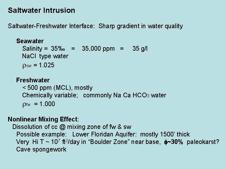
Saltwater Intrusion Saltwater-Freshwater Interface: Sharp gradient in water quality Seawater Salinity = 35‰ = Na. Cl type water rsw = 1. 025 35, 000 ppm = 35 g/l Freshwater < 500 ppm (MCL), mostly Chemically variable; commonly Na Ca HCO 3 water rfw = 1. 000 Nonlinear Mixing Effect: Dissolution of cc @ mixing zone of fw & sw Possible example: Lower Floridan Aquifer: mostly 1500’ thick Very Hi T ~ 107 ft 2/day in “Boulder Zone” near base, f~30% paleokarst? Cave spongework
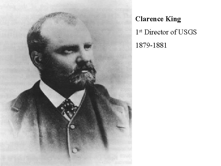
Clarence King 1 st Director of USGS 1879 -1881

- Slides: 69