DAF System Air Supply Pressurizing Pump Retention Tank


 of the clarified effluent from the")


 35 Air Solubility, ml/L 30 Temp.")


 W = effective width (m) L")


- Slides: 28
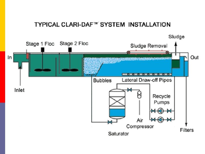
DAF System § Air Supply § Pressurizing Pump § Retention Tank § Flotation Chamber
SKEMATIK PROSES DAF
DAF Configuration § Full Flow Pressurization § Partial Flow Pressurization § Recycle Flow Pressurization
Full Flow Pressurization § The entire influent feed stream is pressurized by a pressurizing pump and held in the retention tank § The system is usually applicable to the feed stream with suspended solids exceeding 800 mg/L in concentration § It is not susceptible to the shearing effects caused by the pressurizing pump and the high pressure drop at the pressure release valve § Suspended solids will flocculate rapidly with the addition of chemical coagulants in the inlet compartment in the presence of the released air
Partial Flow Pressurization § Only about 30– 50% of the influent feed stream is pressurized by a highpressure pump and held in the retention tank. § Materials with low specific gravity can be removed with the partial flow pressurization system. § The increased hydraulic flow on the flotation chamber due to the flow recirculation must be taken into account in the flotation chamber design.
Recycle Flow Pressurization § A portion (15– 50%) of the clarified effluent from the flotation chamber is recycled, pressurized, and semisaturated with air in the retention tank. § The system is usually employed in applications where preliminary chemical addition and flocculation are necessary ahead of flotation. § This system is not recommended for use when the suspended solids are susceptible to the shearing effects of the pressurizing pump and the highpressure drop at the pressure release valve. § The suspended solids concentrations are low.
Faktor-Faktor Yang Mempengaruhi Kinerja DAF § Sifat Partikel § Ukuran Partikel § Dispersing Agents § Komposisi dan sifat Influent § Arus Cairan § Rasio A/S § Float Removal
Sifat Partikel § The specific gravity is a characteristic of the particle or liquid to be abated or separated. § It can easily be accepted that sand, for example, cannot be floated while voluminous material, such as activated sludge, or a water immiscible liquid such as oil, can be floated.
Ukuran Partikel § Generally, floatability increases with the size of the particle. § In many cases, the size of particles can be increased by flocculation with various chemical coagulants.
Dispersing Agents § Certain wastewaters and liquids contain unusual concentrations of various chemicals, resulting in specific flotation problems or advantages. § Surfactants, such as detergents, tend to alter the physical properties of the sludge particle surface to be floated.
Komposisi dan sifat Influent § The composition and nature of the influent is most important. § Equalization of composition and flow improves the performance of the flotation unit.
Arus Cairan § The liquid currents are governed by the physical design and hydraulics of the flotation unit. § This becomes a consideration in the design of the tank and hydraulic loadings of the flotation unit.
Rasio A/S § The amount of air and the method of mixing the air with the material to be floated are functions of the design of a particular flotation unit. § For a specific application, a definite amount of air is necessary for flotation. § In thickening applications it has been shown that increased performance is obtained at higher A/S ratios.
Air to Solids Ratio
Float Removal § A float-removal mechanism must be designed to have adequate capacity to remove water carryover. § Various items to be considered in this design are the depth of submergence of the scooping mechanism and the speed of scoop operation.
Gas to Solids Ratio : Full Flow Pressurized System G Q Cf X Gin Gout Q Cr Q Ce G Correction factor, F or f, because complete gas saturation of liquid is often not achieved in a pressurized retention tank Henry’s law P ≥ 2 atm F = 0, 5 – 1, 0 P < 2 atm f = 0, 167 – 1, 0
Gas to Solids Ratio : Q Cf X Partial Flow Pressurized System G Qn Cf G Gin Gout Q Ce Qp Cr P ≥ 2 atm F = 0, 5 – 1, 0 P < 2 atm f = 0, 167 – 1, 0 The Qp/Q ratio ranges between 0. 3 and 0. 5
Gas to Solids Ratio : Q Cf X G Gout Gin Qr Cr R = Qr/Q Recycle Flow Pressurized System Q Ce G P ≥ 2 atm F = 0, 5 – 1, 0 P < 2 atm f = 0, 167 – 1, 0
Air Solubility in Water at 1 Atm (a) 35 Air Solubility, ml/L 30 Temp. o. C Air Sol. (m. L/L) 0 28, 8 10 23, 5 20 20, 1 30 17, 9 25 20 15 10 5 0 0 5 10 15 20 25 Temperature, o. C 30 35 40
Air Characteristics and Solubilities
Pressure Calculations
Design Parameters § Hydraulic loading rate § Solids loading rate § Air to Solids ratio § Retention Tank Pressure
Basic Design Concept The ratio of Q/As is also defined as the hydraulic loading rate VH Q Ac = horizontal velocity (m/s), = influent flow rate (m 3/s), = cross-sectional area of a flotation chamber (m 2) VT D T Q AS = vertical rise rate of suspended solids (m/s), = effective depth of the flotation chamber (m), = detention time (s), = influent flow rate (m 3/s), = surface area of flotation chamber (m 2)
Basic Design Concept D = effective depth (m) W = effective width (m) L = effective length (m) § The D/W ratio is usually between 0. 3 and 0. 5 § F′= factor for short circuiting and turbulence, assumed as 1. 4.
The influence of Loading Rate
DAF Operation and Performance