Cylindrical Grinding Machine Workhead Carriage Tailstock Bed Table

")
Cylindrical Grinding Machine Workhead Carriage Tailstock Bed Table (Courtesy: Micromatic Grinding Technologies Ltd. )
 Workhead 75 mm Applied force Deflection")
Validation of Geometric and FE Models Force (F) Workhead 75 mm Applied force Deflection in µm 150 mm Tailstock Frequency in Hz Mode Experimental Computational (N) Experimental FEA 1 55. 12 62. 67 50 0. 5 0. 41 2 110. 13 108. 16 100 0. 7 0. 82 150 1. 23 200 1. 64 250 2. 06 300 2. 47 Static & Dynamic Tests

SPECIFICATIONS AND MATERIAL PROPERTIES Grinding Wheel specifications 1. Wheel Peripheral speed 45 m/sec Max. Diameter 660 mm Rapid feed rate 10 m/min (max) Feed during rough grinding 3. 75 mm/min (max) Feed during finish grinding 1. 5 mm/min 3. Spindle diameter 80 mm 4. Max RPM 700 (max) 5. Spindle power 11 KW 2. (Courtesy: Micromatic Grinding Technologies Ltd. )

S. No. Component of. CUTTING Direction. FORCES of Values. USED in N Values in force Application (CMTI N (Given handbook) by Industry) 1. 2. Tangential cutting Vertically force downwards Axial force Towards the 244. 3 350 48. 86 70 732. 9 800 workhead 3. Radial force Inwards, towards the operator

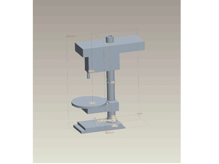
Analysis of Cylindrical Grinding Machine

Analysis of Cylindrical Grinding Machine

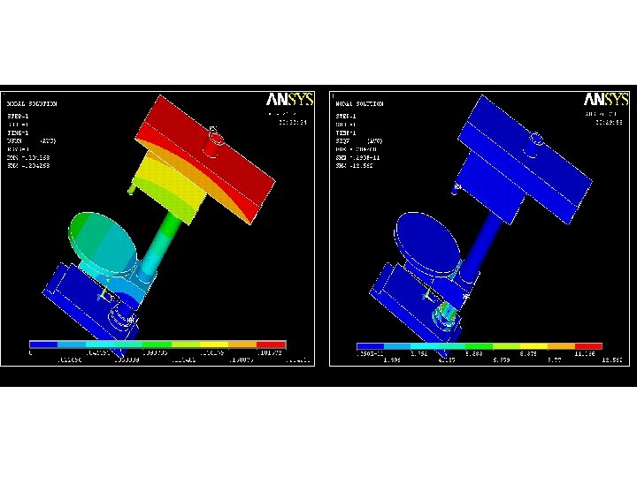
Analysis of Cylindrical Grinding Machine Deformation contour of entire machine tool

Analysis of Cylindrical Grinding Machine
 contour of bed")
Analysis of Bed Deformation (in m) contour of bed

Analysis of Bed

S. No Componen Total X-axis* Y-axis* Z-axis* Von. Mise ts/Sub. Deformati s stress in assemblies on in μm MPa on in μm (max. ) 1. Bed 0. 139 0. 0218 0. 0266 0. 0863 0. 192 2. Carriage 0. 0129 5. 848 e-3 3. 91 e-5 2. 326 e-3 0. 022 3. Workhead assembly 6. 45 1. 86 5. 21 7. 84 4. Tailstock 9. 14 0. 238 2. 11 7. 99 11. 36 5. Workhead +Workpie ce+ Tailstock Entire assembly 7. 22 1. 64 2. 09 5. 92 10. 88 4. 57 0. 585 1. 39 4. 51 9. 99 6. X-axis*- Axial axis Y-axis*- Vertical axis Z-axis*- Radial axis Fx = 70 N Fy = 350 N Fz = 800 N

Parametric Optimization Pre-optimization sensitivity analysis Sensitivity w. r. t. static deflection 0, 01 0 T 1 T 2 T 3 T 4 T 5 -0, 01 -0, 02 Design Variables -0, 03 Sensitivity w. r. t. 1 st Natural Frequency 0, 1 0, 05 0 -0, 05 -0, 15 -0, 2 T 1 T 2 T 3 T 4 T 5

Topology Optimization provides with optimum distribution of material within a specified design space satisfying functional requirements of a part/product. (a) (b) (c) Topology optimization on various components of a cylindrical grinding machine tool (a) Bed (b) Frame of workhead (c) A component of wheel head subassembly

Topology Optimization Preliminary results of possible topology modifications in bed Topology Optimization Results

Topology Optimization Feature based representation of bed for feature sensitivity analysis Feature 1 Feature 2 Feature 3 % Decrease in mass 6. 56 4. 02 8. 38 % Increase in static deflection 2. 13 3. 28 7. 25 % Increase in 1 st Natural Frequency 4. 73 0. 10 8. 37 Feature Sensitivity Analysis Results

Design Case of Bed of Cylindrical Grinding Machine 475 Kgs of bed weight can be reduced by increasing maximum permissible deflection from 3. 6 µm to 3. 9 µm

Machine Tool Design

Machine Tool Design
 12: 40 pm to 3: 45 pm")
Machine Tool Design Initial (12: 40 pm) 12: 40 pm to 3: 45 pm 5: 00 pm (running) (rest) Axial 0 µm 40 µm 10 µm Radial -3 µm 12µm 8µm

- Slides: 28